Transcription
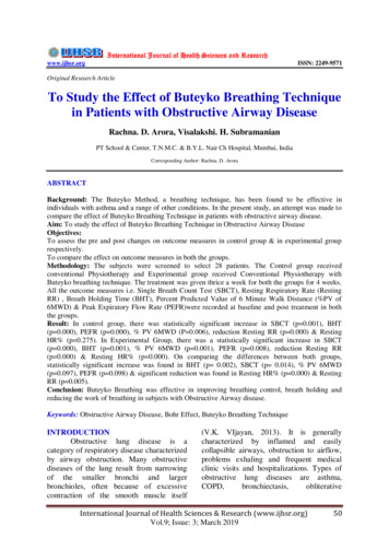
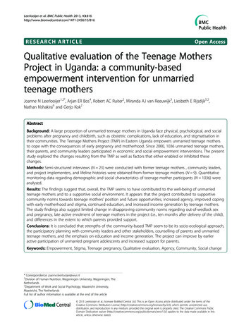
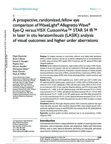
Hindawi Publishing CorporationJournal of RoboticsVolume 2015, Article ID 696301, 9 pageshttp://dx.doi.org/10.1155/2015/696301Research ArticleStudy and Experiment on a Wheat Precision Seeding RobotLin Haibo,1 Dong Shuliang,2 Liu Zunmin,1 and Yi Chuijie31College of Mechanical Engineering, Qingdao Technological University, Qingdao 266520, ChinaSchool of Mechanical Engineering, Harbin Institute of Technology, Harbin 150001, China3Environmental Protection Bureau of Shandong Province, Jinan 250101, China2Correspondence should be addressed to Lin Haibo; haibolin76@163.comReceived 29 April 2015; Accepted 1 November 2015Academic Editor: Yangmin LiCopyright 2015 Lin Haibo et al. This is an open access article distributed under the Creative Commons Attribution License,which permits unrestricted use, distribution, and reproduction in any medium, provided the original work is properly cited.The wheat precision seeding technology provided an advanced agricultural support for the high yield of wheat. But the lack ofeffective agricultural machine made this technique difficult to apply widely. In this paper a wheel mobile robot to achieve the wheatprecision seeding technology was designed. The kinematic model of the robot was built and simulated. And experimental study wastaken under different operating conditions. Because of multiple effort factors, a quadratic orthogonal rotation combination designmethod was applied in the experiments, identifying the main factors by analysis. Then the field test was carried out according to themain factors. The experiment results showed that the qualified rates of seeding exceed 93% in different sowing speed. That reachedthe agronomic requirements of wheat precision seeding.1. IntroductionWith the development of agriculture in China, the traditional intensive and meticulous farming had been unable tomeet the requirements of current agriculture and agronomydevelopment. Using agricultural machinery instead of thetraditional manpower had become a major trend in the world[1, 2]. And the agricultural robot had become an importanttarget in research and development of agricultural machineryengineering [3, 4]. In agricultural robotics research, Japan,the United States, and other countries were in the lead [5, 6].In China it started in these years, and there was a certain gapin technology comparing with the developed countries [7, 8].Wheat is one of major food crops in China. China’s wheatacreage was 24 million hectares in 2013. Increase of wheatproduction was of great significance for China’s food security.Academician Songlie from Shandong Agricultural Universityproposed the wheat precision seeding agronomic techniquesto improve wheat yield. Using Lumai-5 as experimental wheatseed, the experiments results showed that the yield of the precision seeding techniques was greater by 7.5% to 22.3% thanthat of the traditional seeding techniques [9]. However, due tothe special characteristics of the wheat seed grain geometry,now the mechanization for the wheat precision seeding techniques was still in research stage. Automatic agricultural vehicles had received attentions from the 1920s [10]. Especially inthe recent 20 years, with the development of computer andsensor technologies, numerous researches on this subject,particularly agricultural robots, had been reported [11–15]. Inthis paper, a wheel mobile robot was designed and developedfor the wheat precision seeding. A kinematic model was builtfor the four-wheel drive robot, and some experiments weretaken using this machine. It provided a reference for thedesign and product of wheat precision seeding robot.2. Design of the Precision Seeding RobotAccording to the working environment of the robot andthe agronomic requirements of the wheat precision seedingtechniques, this robot was designed with four-wheel drive,the drive system using servo motor, and the steering systemusing stepper motor [16]. To ensure the robot’s load-bearingcapacity and robustness, the frame was welded by rectangularsteel together, seen in Figure 1. Figure 2 was the system blockdiagram of the wheat precision seeding robot. The robot was
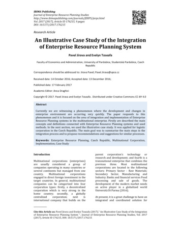
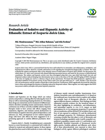
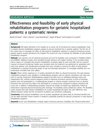
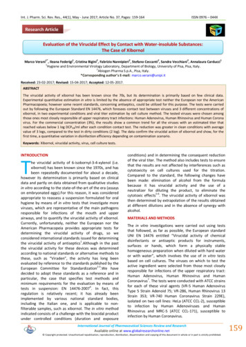
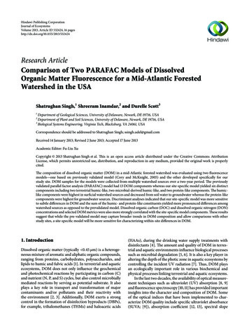
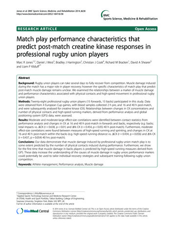
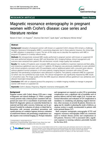
2Journal of RoboticsFigure 1: Wheat precision seeding robot.mainly divided into three parts: the robot mobile body, thecontrol system, and the sensor system. And, the robot mobilebody was divided into the mobile platform and the precisionseeding mechanism. The control system was the core of therobot, seen in Figure 2. It could process the sensor signal andthe information received in the working time. By adjustingthe coherent drive motors, the control system could preciselycontrol the movement of the robot, the picking up and seed ofthe wheat, and the adjustment of the pressure of the vacuumchamber, realizing the agronomic requirements of the wheatprecision seeding.3. Kinematic Model and SimulationFor the mobile robot, the model reflected the relationshipbetween the state variables and control parameters of therobot. So, It was essential to build the model to designan effective tracing control law for small error or no errorrobot trajectory tracking. In this paper, the precision seedingrobot’s platform was designed with 4-wheel drive and 4wheel steering. Rotation and steering of the four wheels arecontrolled independently, there were four servomotors tocontrol each wheel for rotation, and there were also fourstep motors to steer. A central controller coordinated theeight motors to work well together. Theoretically, the fourwheel steering scheme has all the degrees of freedom inthe plane [17]. But, there were many forms that were notpractical in actual application. Figure 3 shows some basicoperation mode. Considering the characteristics and theactual situation of the working in the field, mode (c) wasselected in the design of the wheat precision seeding robot.Two assumptions were made in this paper for the kinematic model of the robot: (1) the platform of the robot wasconsidered as a rigid body and the wheel was considered asa rigid wheel; it was that the elastic deformation of the wheeland the ground was ignored; (2) the robot did not considerthe vertical and pitching motion, excluding the impact of roll.In this paper, we discussed the kinematic model of mobilerobot when front and rear wheels are steering in the oppositedirection, showing in Figure 3(c). Through analyzing thefour-wheel opposite steering mode, there were some certainrelationships in the steering angle between the rear wheelsand the front wheels and the speed between the left wheelsand the right wheels.Figure 4 was the schematic diagram of four-wheel steering mode. 𝑂3 was the instantaneous center of the mobilerobot platform; 𝑃𝑋 𝑌 was the coordinate system of themobile robot; 𝑂2 is the rear wheels’ axis center; 𝑂1 was anintersection point of the line through the point 𝑂3 perpendicular to the body axis and the extended line of the wheels axis;𝑃 is the reference point for precision seeding meter. 𝜙fl wasthe steering angle of the front-left wheel; 𝜙bl was the steeringangle of the rear-left wheel; Vfl was the speed of the front-leftwheel; Vbl was the velocity of the rear-left wheel; V𝑝 was thevelocity of the reference point 𝑃; V𝑜3 was the velocity of 𝑂3 ; 𝑥0was the distance between 𝑂3 and the front wheels axis.Given 𝜙fl , the steering angle of front-left wheel, and 𝜙bl ,the steering angle of rear-left wheel, the following relationshipcould be obtained from the triangle:𝑥0 2𝑙 tan 𝜙fl.tan 𝜙fl tan 𝜙bl(1)By the velocity of rear-left wheel, the robot’s angular velocityaround the instantaneous center could be obtained as𝜔 Vfl sin 𝜙fl Vfl (sin 𝜙fl cos 𝜙fl tan 𝜙bl ) .𝑥02𝑙(2)As 𝑂1 𝑂3 𝑥0 / tan 𝜙fl 𝑏, the velocity of 𝑂3 wasV𝑜3 𝜔 𝑂1 𝑂3 Vfl cos 𝜙fl 𝑏 V sin 𝜙fl .𝑥0 fl(3)The kinematic model of the system could be established with𝑂3 for reference points as𝑥𝑜̇ 3 (Vfl cos 𝜙fl 𝑏 V sin 𝜙fl ) cos 𝜃,𝑥0 fl𝑦𝑜̇ 3 (Vfl cos 𝜙fl 𝑏 V sin 𝜙fl ) sin 𝜃,𝑥0 fl𝜃𝑜̇ 3 (4)Vfl sin 𝜙fl.𝑥0From the relationship of points 𝑂3 and 𝑃, (5) could bederived:𝑥𝑝 𝑥𝑜3 (𝑚 2𝑙 𝑥0 ) cos 𝜃,𝑦𝑝 𝑦𝑜3 (𝑚 2𝑙 𝑥0 ) sin 𝜃,(5)𝜃𝑝 𝜃 𝛼.By taking derivation on both sides of (5), the kinematicsmodel with 𝑝 for reference point was𝑥𝑝̇ V𝑜3 cos 𝜃 (𝑚 2𝑙 𝑥0 ) sin 𝜃 𝜔,𝑦𝑝̇ V𝑜3 sin 𝜃 (𝑚 2𝑙 𝑥0 ) cos 𝜃 𝜔,𝜃𝑝̇ 𝜔.(6)
Journal of Robotics3Robot platformDrive motorReducerFour wheelsSteer motorReducerFour wheelsSensor es48 VSeeding motorSpeedSeeding mechanismVacuum fanEmbedded controllerLead-acidbatteries12 VMotor driverMotor controllerControllerSignal processRemote PCFigure 2: System block diagram of the robot.It wasFirst, straight line trajectory tracking was simulated. Set thelinear equation as follows:𝑥𝑝̇cos 𝜃[ ] [[𝑦𝑝̇ ] [ sin 𝜃[ ]̇[ 𝜃𝑝 ] [ 0(𝑚 2𝑙 𝑥0 ) sin 𝜃] V𝑜 (𝑚 2𝑙 𝑥0 ) cos 𝜃 ] [ 3 ] .𝜔1]𝑥 (𝑡) 𝑡,(7)In (7), V𝑜3 , 𝑥0 , and 𝜔 could be obtained from 𝜙fl and 𝜙bl . Andthe relationship of the left wheels and the right wheels was𝜙fr arctan𝜙br arctan𝑥0 tan 𝜙fl,𝑥0 2𝑏 tan 𝜙fl(2𝑙 𝑥0 ) tan 𝜙fl.𝑥0 2𝑏 tan 𝜙fl(8)𝑥𝑒̇ 𝑘1 𝑥𝑒 𝑦𝑒 𝜔𝑟 𝑘2 V𝑟 𝑦𝑒2 𝑘3 V𝑟 𝑦𝑒 sin 𝜃𝑒 ,𝜃𝑒̇ 𝑘2 V𝑟 𝑦𝑒 𝑘3 V𝑟 sin 𝜃𝑒 .(10)In straight line motion, 𝜔𝑟 0, the velocity was constant,and set V𝑟 1, [𝑘1 , 𝑘2 , 𝑘3 ]𝑇 [5, 5, 5]𝑇 . So the differentialequation of the robot was as follows:𝑥𝑒̇ 5𝑥𝑒 5𝑦𝑒2 5𝑦𝑒 sin 𝜃𝑒 ,𝑦𝑒̇ 5𝑥𝑒 𝑦𝑒 5𝑥𝑒 sin 𝜃𝑒 sin 𝜃𝑒 ,From these equations, when 𝜙bl 0, the front wheel steeringkinematic model of the robot could be obtained.Based on the kinematic model, a trajectory trackingcontroller was built and simulation was taken on the controllaw. The error differential equation of the wheat precisionseeding robot was𝑦𝑒̇ 𝑥𝑒 𝜔𝑟 𝑘2 V𝑟 𝑥𝑒 𝑦𝑒 𝑘3 V𝑟 𝑥𝑒 sin 𝜃𝑒 V𝑟 sin 𝜃𝑒 ,𝑦 (𝑡) 𝑡 1.(11)𝜃𝑒̇ 5𝑦𝑒 5 sin 𝜃𝑒 .The initial location of the robot was 𝑃(0) [0, 0, 0]𝑇 ,the initial location of the desired trajectory was 𝑅(0) [0, 1, 𝜋/4]𝑇 , and Figure 5 was the error curve of straightline tracking. Figure 6 was the actual movement of the robottracking a straight line.From the simulation, the errors of 𝑥 and 𝑦 and the anglebecame 0 after 3.5 s. The actual path and expected path wereoverlapped after 3 s.Then, circular trajectory tracking was simulated. Thecircle equation was𝑥 (𝑡) sin (2𝜋𝑡) ,(9)𝑦 (𝑡) cos (2𝜋𝑡) ,𝜃 (𝑡) 2𝜋𝑡.(12)
4Journal of Robotics(a)(b)(c)(e)(d)(f)(g)Figure 3: Some basic operation mode. (a) Four-wheel same direction steering, (b) front wheel steering, (c) four-wheel opposite steering, (d)differential speed mode, (e) slide steering mode, (f) zero radius steering mode, and (g) braking mode.O1 fl2b𝜙fl X𝜙blyo 3A blY O2ypPxe (m) ye (m) 𝜃e (rad)Y𝛼O3 o 3 px010.80.60.40.20 0.2 0.4 0.6 0.8 1Solution of differential equations: xe , ye , and 𝜃e012l𝜃Omxpxo 3X2345t (s)678910xeye𝜃eFigure 5: Diagram of error curve of straight line tracking.Figure 4: Schematic diagram of four-wheel steering mode.The robot’s initial position was 𝑝(0) ( 0.5, 0.5, 𝜋/2)𝑇 andthe initial position of expected path was 𝑅(0) (0, 1, 0)𝑇 .The expected linear velocity and angular velocity were[V𝑟 , 𝜔𝑟 ]𝑇 [𝜋/12, 𝜋/6]𝑇 . The controller parameter was
Journal of Robotics5112Expected path100.5Actual path06y (m)y (m)8Expected path4 0.52Actual path 100246x (m)81012 1.5 1.5Figure 6: Diagram of the movement of straight line tracking.xe (m) ye (m) 𝜃e (rad) 0.50x (m)0.511.5Figure 8: Diagram of the movement of circular tracking.Solution of differential equations: xe , ye , and 𝜃e1 10.5Table 1: Code variable design level and the value.0LevelValue 0.5 𝑟𝑥0𝑖 Δ 𝑖 𝑟 1𝑥0𝑖 Δ 𝑖0𝑥0𝑖1𝑥0𝑖 Δ 𝑖𝑟𝑥0𝑖 Δ 𝑖 𝑟 1 1.5 20123456Time (s)78910xeye𝜃eFigure 7: Diagram of error curve of circular tracking.[𝑘1 , 𝑘2 , 𝑘3 ]𝑇 [20, 20, 10]𝑇 . The differential equation for thelocation of the robot was as follows:𝑥𝑒̇ 20𝑥𝑒 𝜋10𝜋 2 5𝜋𝑦 𝑦 𝑦 sin 𝜃𝑒 ,12 𝑒3 𝑒3 𝑒𝑦𝑒̇ 𝜋10𝜋5𝜋𝜋𝑥 𝑥𝑦 𝑥 sin 𝜃𝑒 sin 𝜃𝑒 ,12 𝑒3 𝑒 𝑒 3 𝑒6𝜃𝑒̇ 10𝜋5𝜋𝑦𝑒 sin 𝜃𝑒 .33(13)Figures 7 and 8 showed the result of simulation.From the diagram, the errors of 𝑥 and 𝑦 and angle became0 after 3 s. In the movement diagram, the path turned 2 circlesbefore the actual curve to coincide with expected path, so theerror in 𝑦-axis should better be improved.4. Design of Seeding ExperimentsDuring the working, for the robot, the main factors affectingthe quality of seeding were three: the pore size of planting tray,the pressure (negative) of vacuum chamber, and the speed ofthe planting tray [18]. The pressure of vacuum chamber andthe pore size of the planting tray had a direct impact on theleakage rate and reseeding rate. The smaller size needed thebigger pressure, and if the pore size was too small, it wouldcause the absorbing force which was too weak to pick upthe seed, resulting in leakage phenomenon. If the pressurewas too big, it would cause the increase of the reseeding.Meanwhile in the seeding process, if the speed of plantingtray exceeded a certain limit, there was no adequate fillingtime, likely to cause serious leakage phenomenon [19–21].Due to the fact that the impact of these factors onthe qualified rate was not a simple linear relationship, thequadratic orthogonal rotation combination design methodwas taken in this paper to arrange the experiments. Theregression analysis was used to analyze the connectionbetween the factors and determine the relation of primaryand secondary between them.According to the quadratic orthogonal rotation combination design method, the test points were composed of 3 typesof combination [22, 23]; it was𝑛 𝑚𝑐 𝑚𝑟 𝑚0 .(14)And 𝑚𝑐 was the test number of factor point, 𝑚𝑟 was the testnumber of star point, and 𝑚0 was the test number of zerolevel center point. The number of factors was 3, so all the testnumbers were 23.According to the test and experience, the best combination of factors was selected as the zero level of theexperiments, the pore size of the planting tray was 2.4 mm,the speed of the planting tray was 30 r/min, and the pressureof the vacuum chamber was 2.3 kPa. The values and codetable of each level of the 3 factors were determined accordingto the zero level, as shown in Tables 1 and 2.
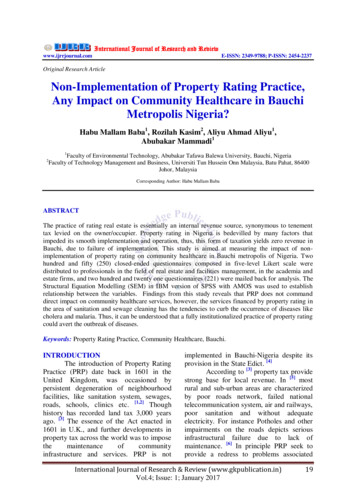
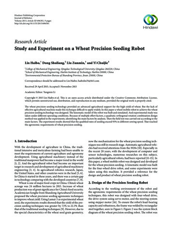
6Journal of Robotics20Table 2: Level code table of tests factors. 1.682 1011.682Pore size𝑥1 /mmSpeed𝑥2 /(r/min)Pressure𝑥3 /kPa2.02.162.42.642.82024303640 1.8 2.0 2.3 2.6 2.81816Seed distribution (%)Level𝑧𝑗141210864202180140 1 2 3 4 5 6 7 8 9 10 11 12 13 14 15 16 17 18Seed space (cm)Figure 10: Statistical chart at 0.9 m/s.1210862041821600 1 2 3 4 5 6 7 8 9 10 11 12 13 14 15 16 17Seed space (cm)Figure 9: Statistical chart at 0.7 m/s.Table 3 was the orthogonal rotation design structurematrix and calculation table of the seeding qualified rate.Because the design factors were the function of the normsvariable 𝑧 confirmed by a dimensionless linear coding, these𝑏𝑖 among the first term regression coefficients and 𝑏𝑖 and theinteraction terms were not relevant. Therefore, the affectionto seeding qualified rate was directly judged by comparing theabsolute values of the norms variable regression coefficient 𝑏𝑖 .So the influence order within a certain range was 𝑥2 𝑥3 𝑥1 . Among them, the speed 𝑥2 was the biggest effect on theseeding performance, the pressure 𝑥3 was less, and the poresize 𝑥1 was the smallest.Based on the above analysis, the conditions for theseeding experiments of the robot were listed in Table 4. Theexperiments were taken under different speeds to verify theperformance of the robot.5. Result AnalysisFor the three speeds, 100 adjacent seed spaces as a samplewere selected from each speed experiment. Tables 5–7 werethe selected data at the speeds of 0.7 m/s, 0.9 m/s, and 1.1 m/s.Figures 9–11 were the statistical chart of the measured seedspace under each speed.According to the standard GB/T6973-2005 (testing methods of single seed drills (precision drills)), the leakage wasthat the seed space was greater than 1.5 times the set distance.Seed distribution (%)Seed distribution (%)16141210864200 1 2 3 4 5 6 7 8 9 10 11 12 13 14 15 16 17 18Seed space (cm)Figure 11: Statistical chart under 1.1 m/s.And the reseed was that the seed space was smaller than 0.5times the set distance. So, the seed space was divided into several ranges: [0, 0.5𝑥], (0.5𝑥, 1.5𝑥], (1.5𝑥, 2.5𝑥], (2.5𝑥, 3.5𝑥],and (3.5𝑥, ]; 𝑥 was the set seed space. Consider𝑛1 𝑛𝑖𝑛𝑖 (0, 0.5𝑥] ,𝑛2 𝑛𝑖𝑛𝑖 (0.5𝑥, 1.5𝑥] ,𝑛3 𝑛𝑖𝑛𝑖 (1.5𝑥, 2.5𝑥] ,𝑛4 𝑛𝑖𝑛𝑖 (2.5𝑥, 3.5𝑥] ,𝑛5 𝑛𝑖𝑛𝑖 (3.5𝑥, ] ,𝑁 𝑛1 𝑛2 𝑛3 𝑛4 𝑛5 .(15)
Journal of Robotics7Table 3: Orthogonal rotation design structure matrix and 12223𝐵𝑖 𝑧𝑦2𝑑𝑖 𝑧𝐵𝑏𝑖 𝑖𝑑𝑖𝑆𝑆𝑖 𝑏𝑖 𝐵𝑖𝑧011111111111111111111111𝑧11111 1 1 1 11.682 1.6820000000000000𝑧211 1 111 1 1001.682 1.68200000000000𝑧31 11 11 11 100001.682 1.682000000000𝑧1 𝑧211 1 1 1 111000000000000000𝑧1 𝑧31 11 1 11 11000000000000000𝑧2 𝑧31 1 111 1 11000000000000000𝑧1 0.4060.4060.4060.4060.4060.4060.4060.4062.2342.234 0.594 0.594 0.594 0.594 0.594 0.594 0.594 0.594 0.594 0.594 0.594 0.594 0.594𝑧2 0.4060.4060.4060.4060.4060.4060.4060.406 0.594 0.5942.2342.234 0.594 0.594 0.594 0.594 0.594 0.594 0.594 0.594 0.594 0.594 0.594𝑧3 0.4060.4060.4060.4060.4060.4060.4060.406 0.594 0.594 0.594 0.5942.2342.234 0.594 0.594 0.594 0.594 0.594 0.594 0.594 0.594 0.5942083.4825.169 45.71527.759 10.880 12.460 0.800 34.979 26.127 015.89015.89090.5861.843 3.3472.032 1.360 1.558 0.100 2.201 1.644 95915.552Table 4: Experiment parameters list.ItemPore sizePressureSeed spaceSpeedValue2.5 2.460.7, 0.9, 1.1UnitmmkPacmm/sDefine the leakage number 𝑛0 , the qualified number 𝑛1 , thereseed number 𝑛2 , and the interval number 𝑁 as follows:𝑛0 𝑛3 2𝑛4 3𝑛5 ,𝑛1 𝑁 2𝑛2 ,𝑁 𝑛2 2𝑛3 3𝑛4 4𝑛5 .The following were the formulas to calculate the reseed rate𝐷, leakage rate 𝑀, and qualified rate 𝐴:𝑛2 100,𝑁𝑛𝑀 0 100,𝑁𝑛𝐴 1 100.𝑁𝐷 (17)Table 8 was the calculation result of the rates under differentspeed.From Table 8, it could be concluded that the qualifiedrates under different speed were all greater than 93%.6. Summary 𝑛2 𝑛1 )Through the above experiments, the results could verify theperformance of the wheat precision seeding robot in theactual work environment. But there were differences underthe different speed. And the speed was the main factor in thewheat precision seeding.
8Journal of RoboticsConflict of InterestsTable 5: Measured data at speed of 0.7 m/s.100 adjacent seed spaces at speed of 0.7 m/s (cm)The authors declare that there is no conflict of interestsregarding the publication of this .08.95.4[1] D. Oetomo, J. Billingsley, and J. F. Reid, “Editorial: agriculturalrobotics,” Journal of Field Robotics, vol. 26, no. 6-7, pp. 501–503,2009.[2] D. Oetomo and J. Billingsley, “Editorial: special issue on agricultural robotics,” Intelligent Service Robotics, vol. 3, no. 4, pp.207–208, 2010.[3] L. Emmi, M. Gonzalez-De-Soto, G. Pajares, and P. GonzalezDe-Santos, “New trends in robotics for agriculture: integrationand assessment of a real fleet of robots,” The Scientific WorldJournal, vol. 2014, Article ID 404059, 21 pages, 2014.[4] S. Shibusawa, “Community-based precision farming for smallfarm agriculture,” in Proceedings of the 6th International Conference on Precision Agriculture [CD-ROM], Minneapolis, Minn,USA, 2002.[5] J. F. Reid, Q. Zhang, N. Noguchi, and M. Dickson, “Agriculturalautomatic guidance research in North America,” Computers andElectronics in Agriculture, vol. 25, no. 1-2, pp. 155–167, 2000.[6] T. Torii, “Research in autonomous agricultu
College of Mechanical Engineering, Qingdao Technological University, Qingdao , China School of Mechanical Engineering, Harbin Institute of Technology, Harbin , China Environmental Protection Bureau of Shandong Province, Jinan , China Correspondence should be addressed to Lin