Transcription
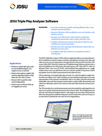
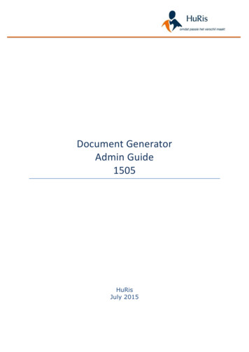
White PaperHow to Measure the True OSNR in ROADM-Based NetworksBy Wolfgang MoenchROADM-Based NetworksReconfigurable Optical Add Drop Multiplexers (ROADMs) are key elements for building a dynamicallyreconfigurable dense wavelength division multiplexing (DWDM) network or Agile Optical Network(AON). The AON accelerates triple-play service deployment and enables advanced wavelength applications at a much lower cost.Figure 1. Agile optical network with ROADMsWhile ROADM-based networks are more economical, they also present new measurement challengesfor optical testing. The optical signal-to-noise ratio (OSNR) is the key performance parameter in opticalnetworks for predicting the bit error rate (BER) of the system. An optical spectrum analyzer used tomeasure the OSNR fairly easily. Now, with ROADM-based networks new measurement methods mustbe deployed.Executive SummarySeveral things are very clear about ROADM-based networks regarding the ability to measure the trueOSNR: The typical signal shape is absent on a ROADM-based network. The OSNR measurement of one filter differs from that of a cascade of multiple ROADMs. A deployed ROADM-based network (typically 15 to 20 ROADMs cascaded) offers a widevariation of filter shapes and signals. Choosing an OSA to install, troubleshoot, and maintain a ROADM-based network requiresgetting the right answer.The following discussion will show that the JDSU Optical Polarization Splitting (OPS) method, basedon the Optical Polarization Nulling technique, is the only field method available to provide the trueOSNR in all ROADM deployment scenarios.WEBSITE : www.jdsu.com/test
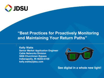
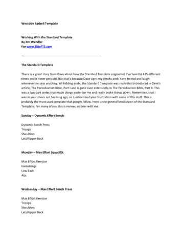
White Paper: How to Measure the True OSNR in ROADM-Based Networks2OSNR Measurement BasicsIEC 61280-2-9 test procedure 2-9 defines the standard for measuring the OSNR. Figure 2 illustrates thelinear interpolation method, which is based on the averaging of the noise levels to the left and right ofthe channel peak leading to the out-of-band OSNR result.PNλiN(λi)OSNR Signal powerNoise powerWavelength of channel i½ x [N(λi- λi) N(λi λi)]P(λi) / N(λi)Figure 2. Linear Interpolation method (IEC 61280-2-9, Test Procedure 2-9The ROADM-based Network ChallengeIn high-speed optical networks based on ROADMs, each channel may traverse through different routes,optical amplifiers, and add-drop filters. As a result of these different paths, noise levels of adjacentchannels may vary. In-line optical filters used for demultiplexing the channels inside the ROADMs alsosuppress the noise in between optical channels. Therefore, using the linear interpolation method (outof-band measurement) gives no indication of the noise present at the actual channel wavelength,resulting in an incorrect OSNR value. Figure 3 shows that getting the true OSNR value requires an inband OSNR measurement.D DemultiplexerM MultiplexerTx TransmitterRx ReceiverFigure 3. Comparison between out-of-band OSNR method and in-band OSNR method
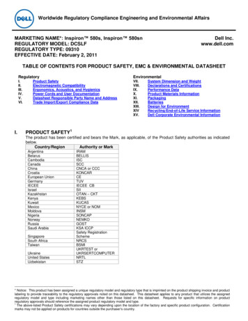
White Paper: How to Measure the True OSNR in ROADM-Based Networks3OSNR Measurement SolutionsTo measure the true OSNR, it is essential to gain access to the noise level inside the optical transmissionband of the ROADM filters, or the in-band noise. Three approaches can be employed to perform “inband” noise measurements:1. Shoulder method software-based solution with conventional optical spectrum analyzer (OSA)2. Polarization diversity detection limited polarization nulling technique3. Polarization splitting method advanced polarization nulling techniqueThe following provides a closer look at the three solutions.Shoulder MethodTheory:Some test vendors may claim that even though the automatic OSNR measurement is wrong, one canmanually measure OSNR with visual markers. This is the shoulder method. The “shoulder method” isbased on the assumption that there will be a hump on either side of the peak indicating the noise shapeof the optical filter, as shown in Figure 4. With the manual mode, the noise is measured at this hump.Figure 4. OSNR measurement based on shoulder methodResult:In high-speed optical networks the bandwidth of the optical signal will almost be as large as the filterbandwidth leading to a very smooth transition between the noise and the signal.Figure 5 shows the situation for 10 Gbps and 40 Gbps signals passing a single ROADM with 100 GHzfilter ( 100 GHz channel spacing).Figure 5. Optical spectrum of 10 Gbps and 40 Gbps after a ROADM (the red trace shows the measurement result of an OSA)
White Paper: How to Measure the True OSNR in ROADM-Based Networks4For better understanding, the noise floor inside the transmission band indicating the ROADM filtershape is indicated in green. A small hump is present for 10 Gbps signals but no hump is present at 40Gbps. In ROADM-based networks, multiple ROADMs are cascaded leading to a narrowing of the filtershape making it almost impossible to detect a hump for accurate noise measurement even at 10 Gbps.Conclusion:The shoulder method makes it impossible to accurately measure the in-band noise floor in high-speednetworks at data rates of 10 Gbps or higher (40/43 Gbps), which makes it impossible to measure thetrue OSNR.Polarization Diversity DetectionTheory:Polarization diversity detection is based on the polarization nulling principle supported by the fact thatthe optical transmission signal consists of arbitrary polarized light, whereas the amplified spontaneousemission noise (ASE) consists of only non-polarized light. Installing an optical polarizer in the lightpath will either block or pass the optical signal depending on the state of polarization (SOP) of theinput signal. The block diagram in Figure 6 shows the polarization diversity detection technique.The polarization splitter will separate the input signal in two orthogonal polarization states (SOP-1 andSOP-2) suppressing the polarized transmission signal and passing the non-polarized noise.Figure 6. Block diagram polarization diversity detectionThough not common, some within the industry believe that by separating two orthogonalpolarizations there is always a condition that shows the noise shoulders, which allows for directmeasurement of in-band noise.Result:In ROADM-based systems the SOP of the optical transmission signal varies from channel to channel.The polarization splitter provides a fixed SOP. The suppression of the polarized transmission signaldepends on the matching of the SOP between the input signal and the polarization splitter. Thesuppression can vary by 15 to 20 dB as shown in Figure 7.
White Paper: How to Measure the True OSNR in ROADM-Based Networks5Figure 7. OSNR measurement without using a polarization controllerThe screen shows three 10 Gbps channels passing a ROADM built with 100 GHz optical filters.The green curve shows the original trace of the OSA. The blue and the red traces show themeasurement result of the two SOPs achieved by polarization-diversity detection.As shown, the suppression of the signal differs from channel to channel. Whereas Ch3 shows highersuppression of the polarized transmission signal to estimate the noise shoulder, it is not possible toaccess the noise shoulder in Ch1 and Ch2 as the suppression is too low, which leads to a highmeasurement uncertainty with this method.Conclusion:Using polarization diversity detection makes it impossible to reliably measure the in-band noise and,therefore, impossible to measure the true OSNR.
White Paper: How to Measure the True OSNR in ROADM-Based Networks6Optical Polarization Splitting MethodTheory:The drawback of polarization diversity detection is that the suppression of the polarized transmissionsignal depends on the matching of the SOPs between the transmission signal and the polarizationsplitter. JDSU provides an improved solution using an integrated variable polarization controller toadjust the polarization of the input signal to match the polarization splitter. This method is calledOptical Polarization Splitting (OPS) method.A polarization controller is used to adapt the SOP of the input signal to the polarization splitter for amaximum suppression of the polarized signal. The polarization splitter will separate the SOP in twoorthogonal states (SOP-1 and SOP-2). The polarization controller is adjusted individually for eachoptical channel. Using the measurement result from SOP-1 and SOP-2 simultaneously, it is possible toobtain the true OSNR.Figure 8. Block diagram of OPS methodResult:Figure 9 shows the spectrum of a three-channel 10 Gbps system passing a ROADM built with 100 GHzoptical filters.Figure 9. Measurement result of JDSU OPS method
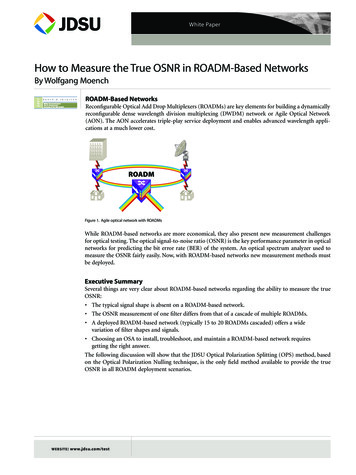
White Paper: How to Measure the True OSNR in ROADM-Based Networks7The green trace shows the signal noise measured with the OSA.The red trace shows the suppression of the polarized transmission signal indicating the noise floor(in-band noise) measured using the OPS method thus leading to the true OSNR.The OPS method will suppress the transmission signal individually for each channel providing accessto the in-band noise floor. There is no limitation due to a missing shoulder or due to high bandwidthsignals, for example, at 40 Gbps or 100 Gbps.For further details, please refer to the JDSU technical note, “In-service measurements of the OSNR inROADM-based Networks.” Please contact the author, Wolfgang Moench, at wolfgang.moench@jdsu.com if you are interested in receiving a copy of the technical note.Conclusion:The OPS method makes it possible to measure the true OSNR of all optical channels with high accuracyunder all conditions independent from data rate and modulation format.Test ResultsTo verify the different methods used to measure the true OSNR in ROADM-based networks, use thefollowing test setup with eight channels passing two ROADMs, as shown in Figure 10.Figure 10. Test setup with eight channelsChannels 1, 2, 4, and 8 pass through the express route in the ROADMs.Channels 3, 5, 6, and 7 were added in the ROADMs.
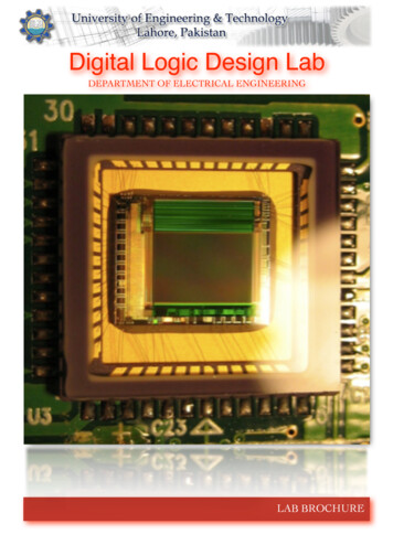
White Paper: How to Measure the True OSNR in ROADM-Based Networks8Figure 11 shows the results of using different methods to measure the OSNR.Ch12345678Measured OSNREExpectedOSNRS30,0 dB30,0 dB14,0 dB28,5 dB13,8 dB13,8 dB13,8 dB28,0 dB28,3 dB23,2 dB18,0 dB15,6 dB12,2 dB16,4 dB26,4 dB28,8 dB29,6 dB30,8 dB15,3 dB22,8 dB13,7 dB14,2 dB14,1 dB23,2 dBJDSU29,5 dB29,6 dB13,9 dB28,1 dB13,4 dB13,6 dB13,5 dB28,5 dBFigure 10. Test setup with eight channelsThe results in Figure 11 show that the traditional, out-of-band OSNR measurements failed in five out ofeight channels by 3-13 dB (red fields in column S). Measuring the OSNR based on the polarizationdiversity detection results in incorrect OSNR values for three out of eight channels (orange fields incolumn E). The only method providing accurate measurements for all channels is the JDSU OPS method(green fields in JDSU column).Conclusion:The JDSU OPS-method with integrated polarization controller is the ONLY method that providesaccurate and reliable measurements of the true OSNR in all ROADM deployment scenarios.References:JDSU Technical Note:“Measuring the Optical Signal-to-Noise Ratio in Agile Optical Networks”W. Moench, J. Larikova,“In-service measurements of the OSNR in ROADM-based Networks,” ECOC 2007 P118All statements, technical information and recommendations related to the products herein are based upon information believed to be reliable or accurate. However, the accuracy or completeness thereof is not guaranteed, and noresponsibility is assumed for any inaccuracies. The user assumes all risks and liability whatsoever in connection withthe use of a product or its application. JDSU reserves the right to change at any time without notice the design,specifications, function, fit or form of its products described herein, including withdrawal at any time of a productoffered for sale herein. JDSU makes no representations that the products herein are free from any intellectualproperty claims of others. Please contact JDSU for more information. JDSU and the JDSU logo are trademarks ofJDS Uniphase Corporation. Other trademarks are the property of their respective holders. 2008 JDS UniphaseCorporation. All rights reserved. 30149304 000 0208 OSNRROADM.WP.LAB.TM.AETest & Measurement Regional SalesNORTH AMERICATEL : 1 866 228 3762FAX : 1 301 353 9216LATIN AMERICATEL : 55 11 5503 3800FAX : 55 11 5505 1598ASIA PACIFICTEL : 852 2892 0990FAX : 852 2892 0770EMEATEL : 49 7121 86 2222FAX : 49 7121 86 1222www.jdsu.com/test
works OSNR Measurement Basics IEC61280-2-9testprocedure2-9d