Transcription
A4, Empower3Processing Tips and TricksRune Buhl Frederiksen,Manager, Waters Educational Services 2012 Waters Corporation1
Content Basic Chromatography Workflow Processing Workflow Integration Theory– Traditional Integration Algorithm– ApexTrack Algorithm Exercise 1 Break System Suitability & Noise and Drift Calculations Managing Manually Adjusted Results Exercise 2 2012 Waters Corporation2
Basic Chromatography WorkflowSampling/LoginMethod SetupSequence/RunSamplesEmpowerDatabaseProcess DataReview/PreviewPrint Report 2012 Waters Corporation3
Processing WorkflowCreateProcessingMethod 2012 Waters CorporationRunSampleSetBringSample SetTo reviewCheck/AdjustMethodSave theChangesProcessSampleSet4
Processing Workflow (continued)BringResults SetTo reviewResults SetSign OffResults 2012 Waters CorporationPrintResultsSet5
Creating a Processing Method Optimizing Integration Component table System Suitability Calculations Noise & Drift Calculations 2012 Waters Corporation6
Integration Integration requires three operations:1. Find the peak (peak detection)2. Find the baseline of the peak3. Compute the peak’s area and height The first two are the challenge Empower has two different algorithms to performintegration–Traditional–Apex Track 2012 Waters Corporation7
Traditional Integration4 Global ParametersTraditional Integration Peak Width and Threshold work together todetect the peaks from the baseline.4 Global Parameters Peak WidthThresholdMinimum AreaMinimum Height 2012 Waters Corporation8
Traditional IntegrationPeak Width DeterminationPeak Width Peak width is measured at the baseline of thenarrowest peak of interest and is used todetermine a bunching factor.160 Bunching Factor Peak Width x Sampling Rate 415B1 2012 Waters CorporationB2B3B4B5B69
Traditional IntegrationDetermining peak startThreshold Specifies the liftoff and touchdownvalues (minimum rate of change ofthe detector signal) for peakdetection. Empower averages the signal slopeacross 3 data bunch intervals andcompares to the liftoff threshold When the average slope of thesignal between the 3 bunches is the liftoff threshold value, point B1is flagged as possible peak start Individual points in bunch B1 isthen examined to determine peakstart data point with lowest YvalueB2 - B1slope 1 t2 - t1 2012 Waters CorporationB3 - B2slope 2 t3 - t2average slope slope 1 slope 2210
Traditional IntegrationDetermining peak apex Signal is monitored untilslope sign changes frompositive to negative Bunch where the slopechange occurs (B12 inthe figure) is analyzed. Data point which isfarthest away from thebaseline is tentativelyassigned as peak apex Final apex is determinedafter integration andbaseline assignment 2012 Waters Corporation11
Traditional IntegrationDetermining peak end Slope of the signal iscompared to the touchdownthreshold When 2 consecutive slopesare threshold, last point inthe last bunch is flagged aspossible peak end Individual points in thisbunch and the next bunchto determine actual peakend data point with lowestY-value 2012 Waters Corporation12
Traditional IntegrationMinimum Height or Minimum AreaMinimum Height or Minimum Area Defines minimum peak area (mV*sec) or minimum peakheight (µV) that Empower will report Used to reject unwanted peaks once integration has beenoptimized Empower use 95% of the peak’s area/ height so that it canreport peaks that approach the selected peak’s size 2012 Waters Corporation13
Traditional IntegrationTimed Events ParametersTimed Events a time-based action to adjust peak detection and/orintegration in specified sections of a chromatogram There are 20 integration events that can be used to fine-tuneintegration across selected regions of a chromatogram You might need to apply one or more timed events when thedefault peak detection and integration parameters do notadequately detect and integrate all peaks in thechromatogram. 2012 Waters Corporation14
Traditional IntegrationTimed Events II – Inhibit Integration TS – Tangential Skim SPW – Set Peak Width ANP – Allow Negative Peaks SLO – Set Liftoff FDL – Force Drop Line STD – Set Touchdown FBT – Force Baseline by Time SMA – Set Minimum Area FBP – Force Baseline by Peak SMH – Set Minimum Height FHP – Forward Horizontal by Peak SMxA – Set Maximum Area FHT – Forward Horizontal by Time SMxH – Set Maximum Height RHP – Reverse Horizontal by Peak VV – Valley to Valley RHT – Reverse Horizontal by Time ES – Exponential Skim FP – Force Peak 2012 Waters Corporation15
ApexTrack IntegrationA New Approach to the Integration of Chromatographic Peaks Easier than traditional integration Better than traditional integration Based on measuring the curvature (the rate of change ofslope) of the chromatogram (2nd derivative) Traditional integration detects peaks by initially looking for apeak start ApexTrack integration detects peaks by initially looking for thepeak apex 2012 Waters Corporation16
ApexTrack IntegrationEasier: Automatically determines appropriate integration parametersettings– Auto Peak Width– Auto Threshold Usually integrates well at first pass using default andautomatic parametersBetter: Integrates negative peaks effectively Integrates small peaks in noisy or drifting baseline effectively Peak shoulders are easily detected Gaussian skimming available 2012 Waters Corporation17
Basis of ApexTrack:Curvature Threshold Detects the peak apex when the curvature is abovethe threshold Effective:– Detects shoulders– Baseline slope does not affect detection of peaks– Peak detection and baseline determination are decoupledoBaseline placement can be modified without affecting the numberof peaks detected and vise versa 2012 Waters Corporation18
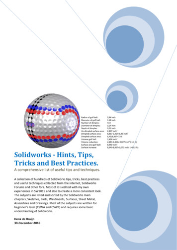
Second Derivative Measures CurvatureGaussian peak1210.80.60.440.2Curvature1. Apex43High (-)0-10-8-6-40246810Second derivative43240.5-202. Inflection Zeropoints3.Liftoff/TDHigh ( )4. BaselineZero-0.5-1-10-8-6 2012 Waters Corporation-41-2024681019
Apex Track IntegrationApex detection parameters Start (min) (Start Detection/Integration Time) End (min) (End Detection/Integration Time) Peak Width (sec) (Peak Width @ 5% Height)—AUTOoRecommended range 0.5 to 2 times Auto PW value Detection Threshold (Peak Detection Threshold)—AUTOBaseline determination parameters Liftoff %– Baseline start threshold %. Default:0Touchdown %–Baseline end threshold %. Default:0.5Peak acceptance criteria Minimum Area (works in the same way as in traditional int.) Minimum Height (works in the same way as in traditional int.) 2012 Waters Corporation20
ApexTrack Peak Detection Peak detection is controlled by the Peak Width and Thresholdparameters Peak Width: measured in seconds, Auto Peak width sets it to5% height of the largest peak in the second derivative(determined by using the inflection point width andcalculating the gaussian peak width); used as a filter similarto traditional integration. Threshold: measured in units of height, Auto Threshold setsit to the peak to peak noise; used as a threshold for peakdetection in the 2nd derivative 2012 Waters Corporation21
PeakWidth2nd derivative plotAutoWidth 2012 Waters Corporation22
Threshold2nd derivative plotAutoThresholdAutoWidthPeak to peaknoise 2012 Waters Corporation23
Apex detection2nd derivative plotApex DetectionApex DetectionAutoThresholdConsidered as noiseAutoWidth 2012 Waters Corporation24
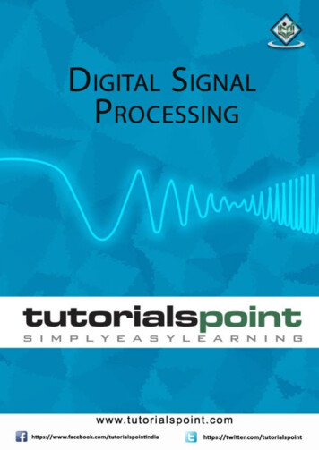
Apex Track IntegrationWhat happens?1. Acquire the data2nd derivative plot2. Obtain chromatogram’sApex Detectionsecond derivative3. Determine peak width(AutoPeakWidth)4. Determine threshold(AutoThreshold)Apex Detection5. Detect peaks- Second Derivative6. Identify inflection pointsConsidered as noiseAutoThresholdAutoWidth 2012 Waters Corporation25
Apex Track IntegrationBaselineResolved PeakFused Peaks(Valley)Fused Peaks(Shoulder)Fused e PlotIntegratedChromatogram 2012 Waters Corporation26
Apex Track IntegrationBaseline DeterminationWhat about Baseline determination? ApexTrack uses percentage slope threshold.oThe slope threshold depends on peak heightoThe baseline is the same for all peaksWhy? Baselines change when concentration changes and the location oftouchdown is most sensitive.What happens? User specifies baseline threshold as a percentage of peak height. Algorithm computes a separate slope threshold for each peak Slope threshold is then proportional to peak heightoBig peaks have big thresholdoSmall peaks have small threshold 2012 Waters Corporation27
Baseline Determination1.2.Initially draws baseline between the inflection pointsDetermines slope differences ( m)using tangents to theinflection pointsPeakstart m1 x Liftoff%/100Peakstop m2 x Tuchdown%/100 m13. m2Determines slope thresholds using Baseline % Thresholdsfrom processing method and slope differences.Baseline % Thresholds scale inflection point slopedifferences to determine liftoff and touchdown points. 2012 Waters Corporation28
Baseline Determination4. Baselines start at the “inflection point” baseline5. Baselines are expanded until the slope threshold criteria aremet6. A Baseline % Threshold of 100 % yields baseline at inflectionpoints7. A Baseline % Threshold of 0 % yields baseline that is tangentto baseline noise 2012 Waters Corporation29
Concentration Change:Traditional Approach Height ratios of 1: 1/10: 1/100 Times of liftoff andtouchdown change Biggest peak:Touchdown far down intail 2012 Waters Corporation30
Concentration Change:Zoom In Focus on 1/10 peak Middle peak:Touchdown is wellpositioned 2012 Waters Corporation31
Concentration Change:Zoom In Again Focus on 1/100 peak Smallest peak:Touchdown is high upthe tail Relative area ofsmallest peak isreduced! 2012 Waters Corporation32
Concentration Change:ApexTrack Height ratios of 1: 1/10: 1/100 Liftoff is the same foreach peak. Touchdown is the samefor each peak Biggest peak:Touchdown is wellpositioned 2012 Waters Corporation33
Concentration Change:Zoom In Focus on 1/10 peak Middle peak: Touchdownis well positioned 2012 Waters Corporation34
Concentration Change:Zoom In Again Focus on 1/100 peak Smallest peak:Touchdown is wellpositioned Note different slopethresholds 2012 Waters Corporation35
Changing %Touchdown Focus on Big peak A small change in the%Touchdown will have abig impact on the slopefor the big peak becauseit is a percentage of thepeak height This will have very littleeffect on the middle peakand NO effect on thesmall peak 2012 Waters Corporation36
Apex Track IntegrationTimed Events ANP - Allow Negative Peaks SMA - Set Minimum Area DS - Detect Shoulders SMH - Set Minimum Height GS - Gaussian Skim SMxH - Set Maximum Height TS - Tangential Skim SMxA - Set Maximum Area II - Inhibit Integration VV - Valley-to-Valley MP - Merge Peaks (for GPC only) SPW - Set Peak Width SL% - Set Liftoff % SDT - Set Detection Threshold ST% - Set Touchdown % 2012 Waters Corporation37
Integration eventsComparison: Traditional –Apex Track 2012 Waters Corporation38
ConclusionsAdvantages over other Integration Packages1.Automatic parameter determination, for rapid methoddevelopment2.Default parameters superior to those of Traditional3.Curvature detection, for reproducible detection of difficultpeaks and shoulders4.Internally adjusted slope threshold, for accurate baselinedetermination, does not affect peak detection5.Gaussian Skimming 2012 Waters Corporation39
Processing Method 2012 Waters CorporationDefault values4040
Developing an ApexTrack methodPeak width & DetectionThreshold is automaticallyDetermined (14.69 & 4.5)Limit the Apex Detectiontime zone (1.8 – 5.0 min)Default settings41 2012 Waters Corporation41
Developing an ApexTrack methodLower the Touchdown%to 0.142 2012 Waters Corporation42
Developing an ApexTrack methodLower the Touchdown%to 0.0143 2012 Waters Corporation43
Developing an ApexTrack methodSetting min.Area44 2012 Waters Corporation44
Developing an ApexTrack methodAddingGaussian skimevent45 2012 Waters Corporation45
Developing an ApexTrack methodAddingDetect shouldersevent46 2012 Waters Corporation46
Questions 2012 Waters Corporation47
Exercise 1 Optimize existing processing method– Optimize integration– Adjust retention times 2012 Waters Corporation48
System Suitability Calculations 2012 Waters Corporation49
System Suitability TabNew in Empower3 2012 Waters Corporation50
Use Noise Centered on Peak Regionin Blank InjectionBlank InjectionHalf height multiplierfor EP s/n region 20 2012 Waters Corporation51
Choosing the Blank Injection 2012 Waters Corporation52
2012 Waters Corporation53
Setting System Suitability Limits 2012 Waters Corporation54
2012 Waters Corporation55
Noise & Drift Calculations 2012 Waters Corporation56
Empower Noise and Drift Calculations There are 8 different calculations that can be performed: Detector Noise Peak-to-Peak Noise Detector Drift Average Detector Noise Average Peak-to-Peak Noise Average Drift Baseline Noise Baseline Drift 2012 Waters Corporation57
Enabling 2012 Waters Corporation58
Visual Representation of the Least-squares line 2012 Waters Corporation59
Detector Drift Detector drift is the slope of the least-squares line. Drift isexpressed in detector units per hour.– For example, the drift calculation for a UV detector would beexpressed in absorbance units (AU) per hour. Average Drift iscalculated by dividing the data into segments (specified in theprocessing method) and averaging the values for eachsegments. 2012 Waters Corporation60
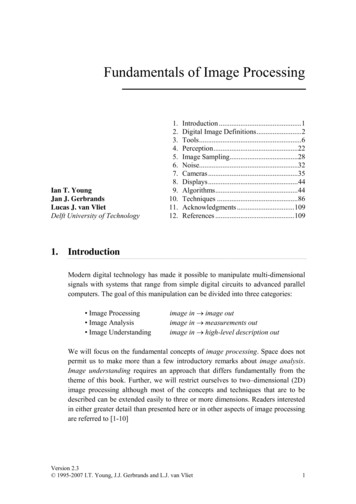
Detector Noise The root mean square (RMS) noise of the data is calculated usingthe least-squares line. The formula for Detector Noise is:2y(i ypi ) n 2 Where yi the y value of the data pointypi the y value of the data point predicted by the linen the number of X10-6 AUResidual 0-5-3.0x10⁻⁵-3.2x10-526.00 2012 Waters .4027.6027.8028.0028.2061
Average Detector Noise2.43X10-6 5-3.0x10-52.7X10-6-3.2x10-526.00 2012 Waters inutes27.4027.6027.8028.0028.2062
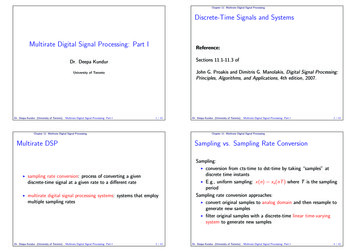
Peak to Peak Noise Peak to Peak Noise is defined to be the algebraic difference of themaximum and minimum residuals between each data point andthe least-square line. The “residual” is determined by subtractingthe y value of the data point predicted by the line from the y valueof the data point. The formula for Peak to Peak Noise is:Peak to Peak Noise Max residual – Min. residual Where Residual yi ypi-1.2x10⁻⁵-1.4x10⁻⁵-1.6x10-51.72X10-5 2.6x10⁻⁵-2.8x10⁻⁵-3.0x10⁻⁵-6.57X10⁻⁶-3.2x10-526.00 2012 Waters .4027.6027.8028.0028.2063
Average Peak to Peak Noise?1.15X10-5 x10-5-3.0x10-51.5X10-5-3.2x10-526.00 2012 Waters inutes27.4027.6027.8028.0028.2064
Baseline Noise and Drift Calculations Baseline Noise setup in SystemSuitability– Peak to Peak Calculation– 30 second segments (notadjustable)– Set time range and percent of runtime. 2012 Waters Corporation65
1.0 2012 Waters Corporation9.066
Viewing the Calculated Results 2012 Waters Corporation67
Managing Manually Integrated Resultsin a Result Set 2012 Waters Corporation68
Managing Manually Integrated Resultsin a Result Set, Samples and ControlsProcessSample SetReviewResult SetPrintResult Set 2012 Waters Corporation Uses Sample Set Information (bracketing) Use Acquisition Method Set (recommended) Manual changes to integration Click Quantitate only DO NOT change standards or click Calibrate Save Result Will ensure that only latest results will be printed69
Managing Manually Integrated Resultsin a Result Set, Samples and ControlsProcessSample SetSample SetReview &Manual integrateResult SetResult Set 1Result Set 1Channel 1046Result 2033Result 2033Channel 1054Result 2039Result 2039Result 2063ManualResult 3741Channel 1073New Version of 2012 Waters CorporationResult 206370
Managing Manually Integrated Resultsin a Result Set, Standards (& Samples/Controls)ProcessSample SetReviewResult SetReprocessResult SetPrintResult Set 2012 Waters Corporation Uses Sample Set Information (bracketing) Use Acquisition Method Set (recommended) Manual changes to integration only DO NOT Calibrate or change proc. method Save Result Select Use Existing Integration Calibrate and Quantitate Will ensure that only latest results will beprinted71
Managing Manually Integrated Resultsin a Result Set, Standards (&Samples/Controls)ProcessSample SetSample SetReview &Manual integrateResult SetResult Set 1Re-ProcessResult SetUse ExistingIntegrationResult Set 1Result Set 2Channel 1046Result 2033Result 2033Result 3834Channel 1054Result 2039Result 2039ManualResult 3836Channel 1073Result 2063ManualResult 3741Result 3849Result 2063New Version of 2012 Waters Corporation72
What happens if you do NOT followthis procedureSample setProcessResult setModified result setChangestdChangesample!! 2012 Waters Corporation73
Questions 2012 Waters Corporation74
Exercise 2 System Suitability Calculations Noise and Drift Calculations Process Sample Set Review and Adjust Results 2012 Waters Corporation75
2012 Waters Corporation 1 A4, Empower3 Processing Tips and Tricks . Ru