Transcription
Technical Information andSystem Application Guide
Table of ContentsTECHNICAL INFORMATION & SYSTEM APPLICATION GUIDEA STRUCTURED CABLING DESIGN CONCEPTB BACKBONE CABLINGC HORIZONTAL DISTRIBUTIOND CABLING SPECIFICATIONSE APPLICATION DESIGNSF TECHNICAL APPENDIXPage 2
Structured Cabling Design ConceptStructured Cabling Design ConceptPage 3A4-6
Structured CablingDesign ConceptTECHNICAL INFORMATION & SYSTEM APPLICATION GUIDEAThe Structured Cabling System plays a critical role in alltelecommunication systems, providing the physical linkbetween sources and destinations of all information. Data,voice, video and control signals are transmitted over thisinfrastructure linking devices across the room, throughout abuilding and across several buildings.The Structured Cabling System is physically configured as aHierarchical Star, where cabling from workstations allemanate from central Floor Distributors (FD) on each floor.The Floor Distributors (FD) or Intermediate DistributionFrames (IDF) in turn, all are fed from a single BuildingDistributor (BD) or Main Distribution Frame (MDF), which inturn is connected back to a Campus Distributor (CD) whenseveral buildings are interlinked.The Structured Cabling System may be quite small andsimple, linking just a few nodes, or it may be massive, linkingIn developing a Structured Cabling System, Molexseveral buildings with tens of thousands of nodes, or arecommends installing Unshielded Twisted Pair (UTP) cablesystem somewhere in between.(or Foil Screened Twisted Pair (FTP) cable where appropriate)Essentially the Structured Cabling System is a simple physical as the horizontal connection between a work station andFD/IDF. The FD/IDF serves as a concentration point andlink between active equipment, and is comprised ofUnshielded Twisted Pair (UTP) cable or Optical Fibre Cable or often accommodates the active LAN switching equipment.combinations of both. However to facilitate the day-to-dayIn medium to large systems which spread across multipleoperations of a normal office environment, the link mustenable the user to make adds, moves and changes wherever floors in a building, the FD/IDF is connected via a backboneand whenever necessary. Furthermore, the Structured Cabling to the BD/MDF, which is the central management point ofthe building. The backbone generally comprises of opticalSystem must also be universal in its ability to carry a widefibre cabling, although voice circuits utilise UTP trunk cabling.variety of applications - from voice and low speed data tohigh speed LAN applications, and to facilitate the migration of The BD/MDF serves to interconnect between FD's/IDF's;an organisation’s network over the life of the cabling system. terminal based computer systems; switch based voicecommunications systems; similar systems in other buildings;Molex divides the entire system into sub-systems (horizontal, and the Public Switched Telephone Network (PSTN).backbone, and system) and addresses each individually,In large systems which spread over several buildings, fibrewhich collectively forms a system that provides all of theand copper links are utilised between buildings, with all linksabove criteria and more. The Molex Structured Cablingrun to a single central distribution point, the CD/CDF.System is standards based and complies with all relevantlocal and international telecommunications cabling standards.Page 4
Structured CablingDesign ConceptTECHNICAL INFORMATION & SYSTEM APPLICATION GUIDEAHORIZONTAL CABLINGHorizontal Cabling is the sub-section of the cabling systemfrom the workstation outlet to the FD/IDF. FD's should belocated so that horizontal UTP cable length is limited to 90metres and Molex recommends that Enhanced Category 5 orhigher UTP (or FTP where appropriate) be installed. This willprovide compliance to industry standards design guidelinesand ensures compatibility with high-speed LAN systems.BACKBONEBackbone cabling provides the main feeder cable in a system.It can be either 'vertical style' in which it runs verticallybetween floors in a building, connecting FD/IDF's to the BD,or 'campus style' in which it connects several BD's inseparate buildings to a CD/CDF in one centralised location.FLOOR DISTRIBUTOR (FD) OR INTERMEDIATEDISTRIBUTION FRAME (IDF)Each FD, also referred to as IDF, should be located so that thehorizontal cabling length is limited to 90 metres. Generally asingle FD/IDF is utilised per floor in an office environment,although several FD/IDF's will need to be established inoffices with large floor areas. This ensures that all horizontalcabling to work stations is limited to no more that 90metres.BUILDING DISTRIBUTOR (BD) OR MAINDISTRIBUTION FRAME (MDF)The BD, provides a means of centralised processing andswitching systems to the vertical backbone cabling.Page 5In a correctly designed horizontal cabling system, theworkstation outlets in each office will be mapped to anappropriate FD. The cable run should be a direct run free ofbridges, taps and splices, although industry standards willallow the introduction of a Consolidation Point (CP) in thelink where appropriate.Molex recommends the use of fibre optic cable in bothinstances although UTP (or FTP where appropriate) is usedfor voice applications in backbones. The fibre backboneinterconnects active LAN equipment to devices situatedthroughout the building or campus.The FD/IDF accommodates all of the cross connect facilitiesto interconnect work stations to active LAN equipment (alsolocated in the FD/IDF enclosure), and backbone cabling tocentralised processing equipment installed elsewhere. TheFD/IDF enables office staff to conveniently make moves andchanges during the course of day-to-day activities.The backbone cabling is terminated in the BD/MDF, togetherwith conversion of termination format where required, so thatall associated cross-connects are matching.
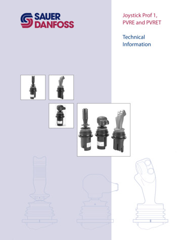
Structured CablingDesign ConceptTECHNICAL INFORMATION & SYSTEM APPLICATION GUIDEADESIGNING A SYSTEMThis section is made up of four parts;This applications guide provides direction and ideas for- Backbone Cabling : Fibredesigning a Molex Structured Cabling System and instructions- Backbone Cabling : UTP/FTPfor interfacing equipment over that system. Following this- Horizontal Distribution : UTP/FTPdesign concept section, there are a number of examples- Horizontal Distribution : Fibrewithin this document of the integration of Twisted Pair andOptical Fibre cabling for specific active equipment applications,to assist in understanding the role structured cabling plays in adata network.1UTP/FTP31 - HORIZONTAL CABLINGHorizontal Cabling begins where the user plugs a terminal in and ends at a centrallylocated point called a Floor Distributor (FD) or Intermediate Distribution Frame (IDF).Distribution Frames should be located so that horizontal UTP/FTP* cable length islimited to 90 metres or less to provide compatibility with high-speed LAN operation.When horizontal cabling is properly designed, each office interface is accessible from anappropriate distribution frame. The cable run should be free of bridges, taps and splices.2UTP/FTP2 - FLOOR DISTRIBUTOR OR INTERMEDIATE DISTRIBUTION FRAMEEach distribution frame should be located so that the horizontal cabling length forUTP/FTP is limited to 90 metres to ensure compatibility with high-speed LAN operation.Sufficient cable management is critical for long term maintainability.Fibre43 - BACKBONEBackbone cabling is the main trunk cable from which all connections are made.Backbone cabling can be either “campus style,” in which it connects several buildings,or it can be run vertically between floors to connect several FD/IDF or the BD/MDF.Molex recommends the use of Optical Fibre cable, although twisted pair, or acombination of both, is acceptable. Applications include baseband LAN, broadband LANand multiplexed channels.4 - BUILDING DISTRIBUTOR (BD) OR MAIN DISTRIBUTION FRAME(MDF)The BD/MDF provides a means of cross-connecting horizontal channels to equipmentports or trunk channels. The ports of each piece of system equipment need to beconverted to the cross connect products mounted in the distribution frame. SystemConnections, Voice and LAN can be incorporated into the BD/MDF.* NOTE : FTP (shielded) cabling systems have traditionally been employed to takeadvantage of their intrinsically improved EMI (electromagnetic interference)performance. A properly installed shielded cabling system offers enhanced immunityand lower emissions than its equivalent UTP system. EMI or RFI (radio frequencyinterference) is any unwanted signal that adversely affects the operation of a deviceor system. Regulations governing emissions from and immunity to the effects ofEMI (electromagnetic interference) are in force worldwide.Page 6
Backbone CablingBOptical Fibre8-11Copper12Page 7
Backbone Cabling Optical FibreTECHNICAL INFORMATION & SYSTEM APPLICATION GUIDEBEXAMPLE DESIGNS:OPTICAL FIBREMolex recommends the use of Optical Fibre as backbonecabling. Properly selected and installed Optical Fibre is the best - A standard star-wired Optical Fibre building backbonedesign for a four floor buildingway to ensure that the backbone will handle the traffic and- Implementation of a bus architecture (Ethernet)provide error-free, universal data transport for the foreseeable- Implementation of a ring architecture (FDDI)future.- Implementation of a hybrid (bus and ring) architecture(Ethernet and FDDI)As with all other premise installations, Molex recommends a- An example of a fault tolerant backbone using redundantstructured approach to Fibre Optic cabling. The followingpathways and bridges (Ethernet)examples provide a guideline for implementing a structured,star-wired Fibre Optic backbone. As the “foundation” of theIn each example, it is assumed that a 19" rack is installed inpremise cabling system, the Fibre backbone provides:each of the four wiring closet locations–the BD or MDF andthree FD or IDFs.- High performance–Gigabit per second and beyond, withthe capability to handle multiple protocols on the samecable.- Security, with centralised network control (from theBD/MDF) over the most “hard-to-tap” media available.- Dielectric data paths eliminate shielding requirements andthe need for dedicated data cable risers or conduits;correctly selected cable may be run in virtually anyenvironment, without regard for EMI issues.In these examples, a single Optical Fibre backbone design willbe proposed for a representative four floor building. The floorsare designated Ground (G), 1, 2, and 3, with the BD/MDF onthe ground floor. Then, the various ways of imposing differentprotocols on the system will be examined, including bus, star,and token ring, without any modification of the backbonecabling. These brief examples illustrate a few of the ways inwhich a Fibre backbone may be used in the premises cablingto take advantage of the superior capacity, security andflexibility of optical communications.TECH TIPBe aware that optic fibre standards have beenrevised in 2002, with ISO and AS/NZS releasingfour new classifications of optical fibre, definingbandwidth and distance capabilities.These new fibre standards have been summarisedin a table in the Cable and ComponentsSpecifications section of this application Guide,along with all UTP cabling standards.Page 8
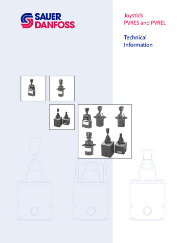
Backbone Cabling Optical FibreTECHNICAL INFORMATION & SYSTEM APPLICATION GUIDEEXAMPLE 1: THE STAR-WIRED OPTICAL FIBREBACKBONEFinally, vertical ring runs are added as appropriate, and theThe MDF is equipped with a Fibre Enclosure containing 72ST ports. Each FD/IDF contains a 24 Port ST panel. A 12- patch panels are labelled with the cable and channel numbers.Advantages to this design are:Fibre cable (six 2-Fibre channels) is installed from theBD/MDF to each of the three FD/IDF's. The cable is tied- All Fibres (six pairs) are terminated and ready for use.down to the designated area at the rear of the Fibre Enclosureusing cable ties around the outer jacket, leaving 1 to 2 metres - The building media is tied down, appropriately strainrelieved, terminated, and stored in the rear of the panelof slack cable, depending on the length required to facilitatewhere it is protected from damage.the termination process. The Fibre Enclosure in the MDF nowhas three cables tied down to the back, while the 24 port fibre - Any unused Fibres are terminated and stored away fromharm, but are ready for use.panel in each FD/IDF has only one cable.- The user accesses only the patch leads, which are easilyreplaced if damaged.After termination, the Fibre connectors should be carefully- The system is star-wired for ease of cable documentationcleaned and plugged into the back of the appropriate adapterbut can be configured into ring format (to support Tokenon the ST Fibre panel according to the colour code. TheRing or FDDI) by using patch leads.remaining slack is stowed into the storage clips in the 24 port- Any floor(s) can be bypassed or included in the backbonefibre panel. (This is easily done by turning coils of the slacksystem from a central control point—the BD/MDF.into the clips, letting the Fibre fall into its natural set).This can be important in multi-tenancy buildings as the FD/IDFMolex recommends an intelligent numbering system basedlocation may not be secured or accessible to the buildingupon the destination and channel number. In the examplemanagement.below, the “F” prefix indicates it is a Fibre Optic cable,followed by the destination FD/IDF, then a hyphen and thechannel within the cable. For example, cable F1 (Fibre Optic#1) runs from the BD/MDF to FD/IDF1 and has 6 channels,resulting in channel numbers 1-1, 1-2, 1-3, etc. For a systemwith two FD/IDF’s on floor 1,they could be designated IDF11and IDF12, or IDF1E (1 East) and IDF1W (1 West). Forexample: The Fibres in each channel are designated “A” and“B” with “A” being “send” at the BD/MDF and “B” being“send” at the FD/IDF (“receive” at the BD/MDF), resulting ina colour code to numbering for cable 1 of:F1-1A Dark BlueF1-2A GreenF1-3A SlateF1-4A RedF1-5A YellowF1-6A Light BlueF1-1B OrangeF1-2B BrownF1-3B WhiteF1-4B BlackF1-5B VioletF1-6B PinkLabelling should be done on the face of the patch panel.Page 9B
Backbone Cabling Optical FibreTECHNICAL INFORMATION & SYSTEM APPLICATION GUIDEBEXAMPLE 2: IMPLEMENTING A BUSARCHITECTURE ON THE OPTICAL FIBREBACKBONEEthernet will be used as the bus example. It is easilyimplemented over Fibre in a star-wired system utilising onepair of Fibres (send/receive) for each channel. Thearchitecture uses an active Fibre switch in the BD/MDF andFibre Optic Transceivers (FOT) in the FD/IDF's.The active Fibre switch is installed in the BD/MDF. A duplexFibre patch lead is connected from a port on the hub to anactive Fibre pair to each floor (three patch leads). This hasnow distributed an Ethernet signal to each floor. Generally, theFibre switch also has an Attachment Unit Interface (AUI) portfor local connection of an Ethernet repeater. If not, anindependent Fibre Optic Transceiver (FOT) is connected into aspare Fibre port.EXAMPLE 3: IMPLEMENTING A RINGARCHITECTURE ON THE OPTICAL FIBREBACKBONEFour megabit and 16 megabit Token Ring networks are easilyimplemented over a Fibre backbone. A newer development intoken-passing technology, however, is the Class A FDDI (FibreDistributed Data Interface) protocol. Class A FDDI is a dualcounter-rotating ring topology using a token passing protocol.100 Mbps Class “A” FDDI is most often implemented as abackbone, linking many individual LANs into a “Super LAN.”At each FD/IDF a duplex patch lead is connected from thenow active Fibre pair to a FOT. This converts the opticalEthernet signal into an electronic signal on an AUI interface.Appropriate equipment for horizontal distribution of theEthernet signal can now be connected to the backbone throughthe AUI ports at each floor.Optionally, a chassis level product may be used. In this case achassis of the appropriate size is installed into each frame(FD/IDFs and BD/MDF). In the BD/MDF chassis amultichannel Fibre card is installed into the concentratorchassis to provide the Active Fibre switch function. The mostcost-effective solution at each FD/IDF is usually anindependent FOT connected into the FD/IDF chassis throughan AUI cable.Molex recommends the use of ST or SC connectors in thepatch field even when the FDDI protocol is implemented.The use of ST or SC connectors will provide the followingadvantages:- All of the backbone Fibres are similarly terminated,allowing the use of any Fibres for any network.- These connectors are easier to install and less expensive.- The use of ST connectors eliminates the need to“reverse” the backbone Fibre pairs to achieve an unevennumber of reversals between FDDI devices.The FDDI system offers a degree of fault tolerance. If achannel is lost, whether through a failure in the media or inthe transceiver electronics/optics, the equipment on each sideof the failure will “loop back” its signals. This creates a single“C” shaped ring from the original “O” shaped dual rings. This All reversals may be achieved by using FDDI to ST or SC patchtechnique is referred to as “self healing”’ in that a link failure cords to connect the devices to the backbone, with a singlereversal made at the BD/MDF interconnection.in the ring will not shut the system down.To create the FDDI ring on the Fibre backbone, an appropriateFDDI device is installed in each FD/IDF. Each of these isserviced and connected through two Fibre channels (fourFibres) back to the BD/MDF. Here another FDDI device isinstalled and a ring topology is created. Notice that the lowerconnection of the BD/MDF - FDDI device is connected througha channel to FD/IDF1 - FDDI device there. The other channelof the device in FD/IDF1 returns to the MDF through a secondOptical Fibre channel where a connection is made to FD/IDF2with a patch lead. FD/IDF2 is connected through the FDDIdevice back to the MDF where it connects to the FDDI devicein the BD/MDF, completing the ring. This creates a star-wiredToken Ring network over Optical Fibre.Page 10
Backbone Cabling Optical FibreTECHNICAL INFORMATION & SYSTEM APPLICATION GUIDEEXAMPLE 4: IMPLEMENTING A HYBRIDARCHITECTURE ON THE OPTICAL FIBREBACKBONEThree pairs of Fibres to each floor are active, with pairs 1 andFDDI equipment is more expensive than the ubiquitous2 as FDDI transport and pair 3 as Ethernet. ThisEthernet equipment, so a method of implementing the FDDInetwork in specific applications is desirable. The lower cost and implementation has the following features:more common Ethernet system can co-exist with the FDDI- Only two high-cost FDDI units are required, the remainingsystem, without interfering with each other and be managedFD/IDF’s are serviced with relatively low-cost Ethernet.independently.- The star-wired backbone enables floors G and 2 to beconnected without routing through any other floors,Shown here is a system based upon a high traffic levelminimising the number of connections and potential failurebetween the systems on floor 2 and the BD/MDF. An Ethernetpoints.backbone connects floors G, 1, and 3. An FDDI network- Should traffic on other floors demand the deployment ofconnects floors G and 2, and the two systems are connectedFDDI, equipment can be easily added into the ring.together in the BD/MDF.EXAMPLE 5: A FAULT TOLERANT BACKBONEUSING REDUNDANT PATHWAYS AND ROUTERSEthernet is used for communications with a plan to providetolerance to media faults by providing two different cableroutes to each FD/IDF location. This is done by using switchesand routing the cables up separate risers. The extendeddistance capabilities of Ethernet over Optical Fibre allows thecables to be routed through risers at opposite ends of thebuilding, minimising the chances of communications failure dueto a problem in the riser.A router has the ability to support two different backboneEthernets, one active and the second a live standby. If aproblem
The Structured Cabling System may be quite small and simple, linking just a few nodes, or it may be massive, linking several buildings with tens of thousands of nodes, or a system somewhere in between. Essentially the Structured Cabling System is a simple physical link between active equipm