Transcription
CHAPTER 3Existing and Future Airport and EnvironsConditions3.1 Existing Airport FacilitiesSFO is located approximately 13 miles south of downtown San Francisco in unincorporated SanMateo County and the active operations area is bordered by the San Francisco Bay to the east,Interstate 380 (I-380) to the north, and U.S. 101 to the west and south. Of the 5,100 acres thatcomprise Airport property, approximately 2,110 acres are located on land east of U.S. 101,180 acres are not actively used for Airport operations and are located west of U.S. 101, and2,810 acres are San Francisco Bay tidal waters. As shown on Exhibit 3-1, the Airport issurrounded by the cities of Millbrae and Burlingame (to the south), San Bruno (to the west), andSouth San Francisco (to the north). Other jurisdictions in the vicinity of SFO include: the City ofBrisbane, the Town of Colma, Daly City, the City of Pacifica, the Town of Hillsborough, the Cityof San Mateo, Foster City, and San Mateo County (i.e., unincorporated areas).Direct access to the terminal buildings and parking facilities is provided by ramps directly fromU.S. 101. Other landside facilities at SFO are accessible from North Access Road (via U.S. 101and I-380 ramps) and San Bruno Avenue (via U.S. 101 ramps). Existing facilities at SFO arepresented on Exhibit 3-2 and summarized in the following sections.3.1.1Airfield FacilitiesAirport RunwaysThere are four runways at SFO: Runway 10L-28R is 11,870 feet long and 200 feet wide; Runway10R-28L is 11,381 feet long and 200 feet wide; Runway 1L-19R is 7,650 feet long and 200 feetwide; and Runway 1R-19L is 8,650 feet long and 200 feet wide. Runway data are summarized inTable 3-1.TaxiwaysA system of taxiways and taxilanes at SFO is designed to connect the four runways to thepassenger terminal complex, air cargo aprons, fixed based operators (FBOs), and general aviationfacilities. Each of the four runways has a full-length taxiway. Runways 28R and 19L have angledtaxiways to expedite aircraft exiting the runways after landing.San Francisco International Airport14 CFR Part 150 Noise Exposure Map Report3-1ESA / 120832August 2015
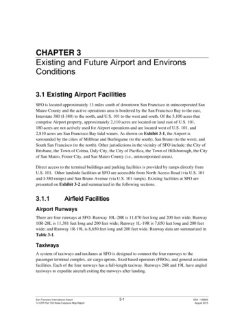
3. Existing and Future Airport and Environs ConditionsTABLE 3-1EXISTING (2014) RUNWAY CHARACTERISTICS, SAN FRANCISCO INTERNATIONAL AIRPORTRunway 10L-28RRunway CharacteristicsRunway 10R-28LRunway 1R-19LRunway 1L-19R10L28R10R28L1R19L1L19RRunway Runway Width200200200200200200200200Displaced Arrival ,0908,6507,0107,650Approach Surface Slope34:150:134:150:120:150:120:134:1Runway End Elevation (Feet above MSL)5.6137.212.711.29.910.58.6Runway ionPrecisionNon-PrecisionNon-PrecisionRunway LightingHIRL, CL, PAPIHIRL, CL, TDZ,PAPIHIRL, CL, PAPIHIRL, CL,PAPIHIRL, CLHIRL, CL, TDZ, PAPIHIRL, CLHIRL, CL,PAPINon-PrecisionRNAV(GPS)PrecisionILS CAT IIICNon-PrecisionRNAV(GPS)PrecisionILS CAT II(SA)VisualPrecisionILS CAT ALSFREILNoRunway Landing Distance AvailablePart 77 Runway Category andNavigational AidsRunway Approach LightingNOTES:Phase 1 of the Runway Safety Area (RSA) Project, which included enhancements to Runways 10R-28L and 10L-28R, was completed in 2013. Runway safety area improvements to Runways 1R and 1L were completed in 2014.Runway data presented in this table were used to develop the 2014 Noise Exposure Map.MSL Mean Sea LevelHIRL High Intensity Runway Lighting; CL Centerline LightingPAPI Precision Approach Path Indicator; TDZ Touchdown Zone lightingREIL Runway End Identifier Lights; ALSF2 Approach Lighting System with Sequenced Flashing LightsMALSR Medium Intensity Approach Light System with Runway Alignment Indicator Lights; MALSF Medium Intensity Approach Light System with Sequenced FlashersILS CAT Instrument Landing System Category; RNAV(GPS) Area Navigation ApproachILS CAT II (SA) Instrument Landing System Category II, Special AuthorizationSOURCES: Airnav.com accessed June 21, 2014; Ricondo & Associates, Inc. Airport Layout Plan, Data Sheet, San Francisco International Airport. January 17, 2014. [III-1]San Francisco International Airport14 CFR Part 150 Noise Exposure Map Report3-2ESA / 120832August 2015
3. Existing and Future Airport and Environs ConditionsThis page intentionally left blankSan Francisco International Airport14 CFR Part 150 Noise Exposure Map Report3-4ESA / 120832August 2015
3. Existing and Future Airport and Environs Conditions3.1.2Passenger Terminal FacilitiesThe SFO terminal complex is located on the east side of the Airport, and has a series of sevenboarding areas, Boarding Areas A through G, that are divided into three domestic terminals andone international terminal.3.1.3Airport Traffic Control TowerThe Airport is serviced by an active FAA airport traffic control tower (ATCT) located in thevicinity of Terminal 2. The ATCT operates 24 hours a day, 365 days a year. Radar approach anddeparture control is operated by the Northern California Terminal Radar Approach Control(NORCAL TRACON) located in Mather, California.3.1.4Other FacilitiesGeneral Aviation FacilitiesGeneral aviation includes all facets of aviation excluding military, air cargo, and scheduledpassenger service. Some of the major categories of general aviation include corporate operations,air taxi operations, flight training, and traffic monitoring. The single FBO at SFO is located northof the end of Runway 10L, and is operated by Signature Flight Support. The facility offersservices to general aviation aircraft including: aviation fuel, terminal and lounge, aircraft parking,maintenance hangers, and pilot services.Air Cargo FacilitiesAir cargo and maintenance facilities at SFO are located on the north side of the Airport alongNorth McDonnell Road. United Airlines and the United State Parcel Service have facilities northof the terminal complex. FedEx Express also uses apron and sorting facilities on the north side ofthe Airport.Other Aviation-related facilitiesA number of aviation-related support facilities are located on airport property. These facilitiesinclude: Aircraft Rescue and Firefighting Facility (ARFF) Aircraft Fueling Facilities Airport Ground Service Maintenance Facility Rental Car Facilities Customs and Border Protection Airport PoliceSan Francisco International Airport14 CFR Part 150 Noise Exposure Map Report3-6ESA / 120832August 2015
3. Existing and Future Airport and Environs Conditions3.2 Future/Planned Airport FacilitiesThe Airport Commission is currently constructing a new ATCT at SFO and the Runway SafetyArea (RSA) Project is nearing completion. Other planned improvements at SFO that will beconstructed prior to 2019 include: (1) an on-Airport hotel; (2) Terminal 3 Modernization;(3) Terminal 1 Redevelopment; (4) South Field Buildings Demolition; and (5) Long Term ParkingGarage Development. The airport layout plan that was conditionally approved by the FAA inJune 2014 is shown on Exhibit 3-3.None of these projects is anticipated to have an impact on aircraft operations (i.e., number andtype of aircraft) at SFO. Future runway characteristics data for SFO are provided in Table 3-2.3.3 Navigational AidsSFO employs several navigational aids, airport lighting, and airport markings to help users of theAirport safely navigate around the Airport and SFO airspace. The navigational aids include:Instrument Landing Systems (ILS), Localizer Type Directional Aid (LDA), Area Navigation(RNAV)/Global Positioning Systems (GPS), and a VOR/DME which is the combination of aVery High Frequency (VHF) Omni-Directional Range (VOR) and Distance MeasuringEquipment (DME). A glossary of terms is provided in Chapter 6 of this report.The Localizer Type Directional Aid is of comparable use and accuracy to a localizer but is notpart of a complete ILS. An LDA approach is not aligned with the runway for either operational orother reason such as terrain. The LDA approach allows the approach course to be offset so thatthere is enough spacing for approach to both parallel runways to be conducted at the same timewhen visibility permits. 1 Straight-in minimums may be published where alignment does notexceed 30 degrees between the course and runway.The GPS uses a network of satellites that create reference points to enable aircraft equipped withGPS receivers to determine their latitude, longitude, and altitude. GPS systems can be used byaircraft during all phases of flight.Area Navigation or RNAV is a method of navigation that permits aircraft operation on anydesired flight path using the combination of both GPS and ground-based navigational aids.RNAV routes and terminal procedures, including departure procedures and standard terminalarrivals, are designed with RNAV systems in mind to save time and fuel, reduce aircraftdependence on air traffic control (ATC) vectoring, and provide for more efficient use of the1Runways at SFO are spaced 750 feet measured from runway centerline to parallel runway centerline, which isinsufficient for the critical design aircraft to conduct simultaneous operations utilizing the runways duringinclement weather conditions.San Francisco International Airport14 CFR Part 150 Noise Exposure Map Report3-7ESA / 120832August 2015
3. Existing and Future Airport and Environs ConditionsTABLE 3-2FUTURE (2019) RUNWAY CHARACTERISTICS, SAN FRANCISCO INTERNATIONAL AIRPORTRunway 10L-28RRunway CharacteristicsRunway 10R-28LRunway 1R-19LRunway 1L-19R10L28R10R28L1R19L1L19RRunway Runway 311,57010,70410,6818,0908,6507,0107,650Approach Surface Slope34:150:134:150:120:150:120:134:1Runway End Elevation (Feet aboveMSL)5.6137.212.710.910.57.19.2Runway ionPrecisionNon-PrecisionNon-PrecisionRunway LightingHIRL, CL, PAPIHIRL, CL, TDZ,PAPIHIRL, CL, PAPIHIRL, CL,PAPIHIRL, CLHIRL, CL, TDZ, PAPIHIRL, CLHIRL, CL,PAPINon-PrecisionRNAV(GPS)PrecisionILS CAT IIICNon-PrecisionRNAV(GPS)PrecisionILS CAT II(SA)VisualPrecisionILS CAT ALSFREILNoDisplaced Arrival ThresholdRunway Landing Distance AvailablePart 77 Runway Category andNavigational AidsRunway Approach LightingNOTES:Runway data presented in this table were used to develop the 2019 Noise Exposure Map.MSL Mean Sea LevelHIRL High Intensity Runway Lighting; CL Centerline LightingPAPI Precision Approach Path Indicator; TDZ Touchdown Zone lightingREIL Runway End Identifier Lights; ALSF2 Approach Lighting System with Sequenced Flashing LightsMALSR Medium Intensity Approach Light System with Runway Alignment Indicator Lights; MALSF Medium Intensity Approach Light System with Sequenced FlashersILS CAT Instrument Landing System Category; RNAV(GPS) Area Navigation ApproachSOURCE: Ricondo & Associates, Inc. Airport Layout Plan, Data Sheet, San Francisco International Airport. January 17, 2014.San Francisco International Airport14 CFR Part 150 Noise Exposure Map Report3-8ESA / 120832August 2015
3. Existing and Future Airport and Environs ConditionsThis page intentionally left blankSan Francisco International Airport14 CFR Part 150 Noise Exposure Map Report3-10ESA / 120832August 2015
3. Existing and Future Airport and Environs Conditionsairspace. A VOR/DME is a facility consisting of two components, VOR and DME. Thisnavigational aid works for civilian aircraft by using a VHF radio to project straight line courses(radials) from the station in all directions that pilots can use to navigate to and from theVOR/DME stations. VOR/DMEs also have distance capability that lets the pilot know their slantrange distance from the station usually shown in the aircraft in nautical miles from the station.SFO has a VOR/DME located at the center of the airfield complex that is operated by the FAA.The VOR/DME at SFO is considered a Class ‘L’ VOR/DME, which has a standard servicevolume limit of 40 nautical miles 2 (nm) between 1,000 feet and 18,000 feet. The SFO VOR/DMEis used to perform a single instrument approach, and is utilized by aircraft executing missedapproach procedures, or aircraft on Departures Procedures or Standard Terminal Arrivals.3.4 Runway Instrument Procedures, Lighting, andMarkingsRunway instrument procedures are published procedures that pilots use to navigate their aircraftto the runway. Runway instrument procedures fall into two categories, precision, and nonprecision approaches. The ILS is a precision approach that has several categories of approachesincluding Category (CAT) I, CAT II, or CAT III A, B, or C. The category of approach that can beflown is based on airport capability (lighting, markings, etc.), aircraft capability, and pilotcertification. The higher the category of approach, the lower the approach minimums (runwayvisual range (RVR) and cloud ceilings) the aircraft can fly before having to have the runway insite, or executing a missed approach. At SFO, Runways 19L, 28L, and 28R have CAT I ILS; onlyRunways 28R and 28L have CAT II approaches, and only Runway 28L has CAT III ILScapability. Table 3-3 presents visibility conversions for RVR values. Below the table is a briefdescription of each of the categories of ILS approaches that SFO employs.TABLE 3-3RUNWAY VISUAL RANGE VALUE CONVERSIONSRVRVisibility (Statute SOURCE: Federal Aviation Regulations/Aeronautical Information Manual (2014) [III-2]The CAT I ILS is the simplest of the ILS approaches that virtually all instrument rated pilots andaircraft can perform. The basic CAT I ILS allows aircraft to descend to an altitude, usually 2002 One nautical mile is equivalent to about 1.15 statute miles.San Francisco International Airport14 CFR Part 150 Noise Exposure Map Report3-11ESA / 120832August 2015
3. Existing and Future Airport and Environs Conditionsfeet above runway altitude, and usually requires a visibility of 2400 RVR or ½ statute miles.Some CAT I ILS will have lower visibility requirements such as 1800 RVR or 3/8 of a statutemile, or could have increased visibility requirements such as 1 statute mile depending on runwayapproach lighting, runway length, terrain, etc.A CAT II ILS allows aircraft to fly the instrument approach to lower minimums than the CAT IILS. Special aircraft and pilot certifications are required prior to executing a CAT II ILSapproach. Generally, CAT II ILS approach minimums allow aircraft to descend to 100 feet aboveairport elevation, and have a visibility requirement of 1200 RVR at most airports.A CAT III ILS allows aircraft to fly to the lowest visibility requirements of which there is nocloud ceiling requirement. There are three categories of CAT III ILS’: CAT IIIA, CAT IIIB, andCAT IIIC. The ability to perform these categories of approaches is based on pilot and aircraftcertification, as well as specific runway capability (approach lighting, runway lighting, etc.).TheCAT IIIA ILS approach allows aircraft to execute the approach to 700 RVR at SFO. The CATIIIB ILS approach allows aircraft to execute the approach down to 600 RVR at SFO. Lastly, theCAT IIIC ILS approach has no visibility requirement allowing aircraft to execute the approachdown to nil visibility conditions. Aircraft capable of performing this CAT III approaches are ableto autoland and track the runway centerline throughout the landing and rollout via the autopilot.Non-Precision approaches including RNAV (GPS), VOR, and LDA have higher approachminimums than ILS approaches due to their lower level of precision. Pilots utilize these nonprecision approaches to SFO’s runways when weather conditions permit.Another type of approach procedure that SFO employs to increase runway capacity ties in withthe ILS, RNAV, and LDA approaches, and is what is called a Precision Runway Monitoring(PRM) approach. Since both parallel runways are only separated by 750 feet centerline tocenterline, simultaneous instrument approaches are not authorized, and staggering aircraft wouldrequire two nautical mile separation. The PRM coupled along with its approach allows controllersto void the separation minimums, but employs a no transgression zone (NTZ) where if an aircraftpenetrates the NTZ, the air traffic controller will issue a ‘breakout’ maneuver clearance to the atrisk aircraft, and a go-around will be initiated. During these approaches, aircraft communicate ontower frequency, but monitor a second tower frequency that monitors the NTZ, and gives‘breakout’ clearances if necessary.3.4.1Runway 10LRunway 10L is 11,870 feet long by 200 feet wide, has precision approach markings and is ingood condition. Runway 10L is served by a RNAV (GPS) approach that provides approachminima of 1,200 foot ceilings above the runway threshold, and one and a quarter statute mile(SM) visibility. Runway 10L has high intensity runway lighting (HIRL), and centerline lighting(CL). A 3.0 precision approach path indicator (PAPI) is located on the left side of the approachend of the runway for aircraft navigating to the runway visually.San Francisco International Airport14 CFR Part 150 Noise Exposure Map Report3-12ESA / 120832August 2015
3. Existing and Future Airport and Environs Conditions3.4.2Runway 28RRunway 28R is 11,870 feet long by 200 feet wide, has precision approach markings and is ingood condition. Runway 28R has a 300 foot displaced threshold reducing the landing distanceavailable to 11,570 feet. Runway 28R is served by a CAT IIIC ILS approach that providesapproach minima down to nil weather conditions. There are also a non-precision approaches toRunway 28R that include: RNAV (GPS), RNAV (GPS) PRM, LDA/DME, and a LDA PRMinstrument approach. When weather conditions permit, Runway 28R has two visual approachprocedures, the Quiet Bridge and the Tip Toe visual approaches. Runway 28R has HIRL, CL, andtouchdown zone lighting, as well as an Approach Lighting System with Sequenced FlashingLights (ALSF2). A 3.0 PAPI is located on the left side of the approach end of the runway foraircraft navigating to the runway visually.3.4.3Runway 10RRunway 10R is 11,381 feet long by 200 feet wide, has precision approach markings and is ingood condition. Runway 10R is served by a RNAV (GPS) approach that provides approachminima of 1,200 foot ceilings above the runway threshold, and one and a quarter statutemile (SM) visibility. However, if aircraft are equipped with RNP, approach minimums arereduced to 400 feet and one and a quarter SM visibility. Runway 10R has high intensity runwaylighting (HIRL), and CL. A 3.0 PAPI is located on the left side of the approach end of therunway for aircraft navigating to the runway visually.3.4.4Runway 28LRunway 28L is 11,381 feet long by 200 feet wide, has precision approach markings and is ingood condition. Runway 28L has a 300 foot displaced threshold, which with declared distances,reduces the landing distance available to 10,681 feet. Runway 28L is served by a SpecialAuthorization (SA) CAT II ILS approach that provides approach minima down to 100 feet abovethe runway threshold. The SA means that the pilots need specific training before shooting theapproach. There are also non-precision approaches to Runway 28L that include an RNAV (GPS),and an RNAV (GPS) PRM approaches. When weather conditions permit, Runway 28L has twovisual approach procedures, the Quiet Bridge and the Tip Toe visual approaches. Runway 28Lhas HIRL, CL, as well as a Medium Intensity Approach Light System with Runway AlignmentIndicator Lights (MALSR). A 3.0 PAPI is located on the left side of the approach end of therunway for aircraft navigating to the runway visually.3.4.5Runway 1RRunway 1R is 8,650 feet long by 200 feet wide, has precision approach markings and is in goodcondition. Runway 1R has a displaced threshold of 560 feet. Runway 1R does not have anyinstrument approach procedures, however, it does have HIRL and CL.San Francisco International Airport14 CFR Part 150 Noise Exposure Map Report3-13ESA / 120832August 2015
3. Existing and Future Airport and Environs Conditions3.4.6Runway 19LRunway 19L is 8,646 feet long by 200 feet wide, has precision approach markings and is in goodcondition. Runway 19L is served by a CAT I ILS approach that provides approach minima downto 300 foot ceilings, and one SM visibility. There are also a non-precision approaches to Runway19L that include an RNAV (GPS), and a VOR approach. Runway 19L has HIRL, CL, andtouchdown zone lighting, as well as a Medium Intensity Approach Light System with SequencedFlashers (MALSF). A 3.0 PAPI is located on the left side of the approach end of the runway foraircraft navigating to the runway visually.3.4.7Runway 1LRunway 1L is 7,650 feet long by 200 feet wide, has non-precision approach markings and is ingood condition. Runway 1L has a displaced threshold of 640 feet. Runway 1L does not have anyinstrument approach procedures, however, it does have HIRL and CL.3.4.8Runway 19RRunway 19R is 7,650 feet long by 200 feet wide, has non-precision approach markings and is ingood condition. Runway 19R is served by a RNAV (GPS) approach that provides approachminima down to 400 foot ceilings, and one and a quarter SM visibility. Runway 19R has HIRL,CL, as well as a 3.0 PAPI that is located on the left side of the approach end of the runway foraircraft navigating to the runway visually.3.5 Runway Assignments and Operational FlowsThere are four primary operational flows/configurations at SFO: 28/1 Operations: During this flow configuration Runways 28L and 28R are the primaryarrival runways and Runways 1L and 1R are the primary departure runways. Runways 28Land 28R are secondary departure runways in this configuration and are typically used byheavy aircraft (cargo and passenger), particularly those headed to international destinations. 28/28 Operations: During this flow configuration Runways 28L and 28R are used forarrivals and departures. This flow configuration is used approximately 9% of the year,typically when there are strong westerly winds and during San Francisco’s Annual FleetWeek Air Show in October. 10/19 Operations: Typically referred to as reverse-flow operations. During this flowconfiguration Runways 19L and 19R are used for arrivals and Runways 10L and 10R areused for departures. This flow configuration is used less than 5 percent of the year and onlyunder certain weather/wind conditions. 10/10 Operations: During this flow configuration arrivals and departures are assigned toRunways 10L and 10R. This flow configuration is used less than 5 percent of the year andonly under certain weather/wind conditions.San Francisco International Airport14 CFR Part 150 Noise Exposure Map Report3-14ESA / 120832August 2015
3. Existing and Future Airport and Environs Conditions3.6 AirspaceThe FAA has six classifications of airspace under the National Airspace System (NAS). Theseclassifications, which are designated Class A, B, C, D, E, and G and shown on Exhibit 3-4, arecritical to the safety of all flights and to the efficient operation of all air traffic control facilities.Based on the level of activity and type of operations, airports receive a classification of B, C, D,E, or uncontrolled airspace.The following paragraphs describe each airspace classification in greater detail, as well as theapplicability of each classification to airspace in the vicinity of San Francisco InternationalAirport. Exhibits 3-5 and 3-6 depict the airspace in the vicinity of the Airport.Class A airspace is designated for positive control of aircraft and ranges from 18,000 feet abovemean sea level (MSL) to 60,000 feet MSL. Within Class A airspace, only aircraft operating underinstrument flight rules (IFR) that are on instrument flight plans are authorized. The aircraft musthave specific equipment and air traffic control (ATC) clearance before entering the airspace. Allairspace at and above 18,000 feet above MSL in the vicinity of San Francisco InternationalAirport is classified as Class A.The airspace immediately surrounding San Francisco International Airport is classified asClass B airspace as designated by solid blue lines shown on Exhibit 3-5. Class B airspace isgenerally defined as that airspace from the surface up to 10,000 feet above MSL. This airspaceusually surrounds the nation’s busiest airports, and is individually tailored consisting of a surfacearea and two or more layers. As shown on Exhibit 3-5, the layers are identified with blue numbersrepresenting the base altitude of the airspace such as (40) or 4,000 feet southwest of SFO in thevicinity of Half Moon Bay Airport. The upper limit of the airspace for San FranciscoInternational Airport is 10,000 feet MSL designated by (100) as the upper number. Class Bairspace can sometimes be described as an “upside down wedding cake” designed to contain allpublished instrument procedures once an aircraft enters the airspace. An ATC clearance isrequired for all aircraft to operate in the airspace, and all aircraft that are so cleared receiveseparation services from other aircraft within the airspace.Aircraft operating under VFR or IFR are permitted into Class B airspace, however, the aircraftmust be equipped with a two-way radio capable of communicating with ATC on appropriatefrequencies, and an operable radar beacon transponder with automatic altitude reportingequipment. For IFR operations, the aircraft must have an operable VOR or TACAN receiver. Thepilot must hold at least a private pilots certificate.Further surrounding the Class B airport is a 30 nm mode C veil designated by a solid magentaline that circles the Class B airspace and extends from the surface upward to 10,000 feet MSL.Unless otherwise authorized, an aircraft operating within the mode C veil must be equipped withautomatic pressure altitude reporting equipment having Mode C radar capability so that theNORCAL TRACON and see all aircraft operating close to the Class B airspace and provideadequate aircraft separation minimums.San Francisco International Airport14 CFR Part 150 Noise Exposure Map Report3-15ESA / 120832August 2015
3. Existing and Future Airport and Environs ConditionsThis page intentionally left blankSan Francisco International Airport14 CFR Part 150 Noise Exposure Map Report3-18ESA / 120832August 2015
3. Existing and Future Airport and Environs ConditionsAs shown on Exhibits 3-5 and 3-6, the airspace in the San Francisco Bay Area region is highlycongested with many airports, both commercial service and general aviation. These airports andairspaces that lie beneath, abeam, or above the SFO Class B airspace include Class C, D, and Eairspace.Class C airspace is the airspace from the surface up to 4,000 feet above the airport elevationcharted in MSL surrounding those airports that have an operational control tower, are serviced bya radar approach control, and that have a certain number of IFR operations or passengerenplanements. Class C airspace is represented by solid magenta lines on Exhibit 3-5, examples ofwhich include Metropolitan Oakland International Airport (OAK) and Norman Y. Mineta SanJose International Airport (SJC). Like Class B airspace, Class C airspace is individually tailoredto meet the needs of the respective airport. The airspace usually consists of a surface area with a5-nm radius from the surface up to 4,000 feet above the airport elevation, and a 10-nm radius thatextends from 1,200 feet to 4,000 above the airport elevation. An example of where the Class Cairspace is individually tailored is OAK’s Class C airspace of which lies entirely beneath the SFOClass B airspace. The extent of OAK’s 5-nm radius is shown from the surface (SFC) to theterminal airspace that lies above (T), or up to, but not including 2,100 feet MSL (21). The same istrue for the outer surfaces of the OAK Class C airspace. Pilots must establish two-way radiocommunications with the ATC facility providing air traffic control services prior to entering theairspace. VFR aircraft are separated from IFR aircraft in Class C airspace.Class D airspace is generally that airspace from the surface to 2,500 feet AGL. Theconfiguration of Class D airspace areas are individually tailored and shown as a dashed blue linewith an altitude representing the extent of the airspace from the surface. When instrumentprocedures are published, the airspace will normally be designed to contain the procedures witheither Class D or E airspace. Class D airspace only surround airports that have an operationalcontrol tower of which pilots are required to establish and maintain two-way radiocommunication with the ATC facility. Examples of Class D airspace throughout the SanFrancisco area include Hayward Executive (HWD), San Carlos (SQL), Palo Alto (PAO), andMoffett Federal (NUQ) airports. Due to airspace constraints, each of these airport have tailoredClass D airspace. For example, PAO’s and NUQ’s airspace abut each other as shown as a dashedblue circle and extends from the surface up to, but not including 1,500 feet AGL under the SJCClass C airspace, but up to 2,000 feet AGL when outside the SJC airspace for PAO; and up to,but not including 2,500 feet AGL for NUQ’s Class D airspace.Class E airspace is generally that controlled airspace that is not Class A, B, C, or D airspace.Class E airspace extends upward from either the surface or designated altitude to the overlying oradjacent controlled airspace. Also in this class are Victor airways, airspace beginning at either700 feet or 1,200 feet AGL used to transition to/from the terminal or en route environments, andoffshore airspace areas designated below 18,000 feet MSL. Unless designated at a lower altitude,Class E airspace begins at 14,500 feet MSL over the United States, including that airspaceoverlying the water within 12 nm off the coast of the 48 contiguous states and Alaska. It does notinclude airspace at or above 18,000 feet MSL. Class E air
REIL Runway End Identifier Lights; ALSF2 Approach Lighting System with Sequenced Flashing Lights . MALSR Medium Intensity Approach Light System with Runway Alignment Indicator Lights; MALSF Medium Intensity Approach Light System with Sequenced Flashers . ILS CAT Instrument Landing System Category; RNAV(GPS) Area Navigation Approach .