Transcription
York Retail System SpecificWiring DiagramsJanuary 2012Using Honeywell ThermostatsClicking on the Virginia Air Logo takes you to the Index Page
Clicking on the Page # takes you to that diagramIndex for Low Voltage Wiring Affinity UnitsOutdoor2 Stage HPYZH2 Stage HPYZH2 Stage HPYZH2 Stage HPYZH2 Stage HPYZH2 Stage HPYZH1 Stage HPYZF 1.5-4 Ton1 Stage HPYZF 1.5-4 Ton1 Stage HPYZF 1.5-4 Ton1 Stage HPYZF 1.5-4 Ton1 Stage HPYZF 1.5-4 Ton2 Stage HPYZF 5-Ton2 Stage HPYZF 5-Ton2 Stage HPYZF 5-Ton2 Stage HPYZF 5-Ton2 Stage HPYZF 5 Ton1 Stage HPYZF 1.5-4 Ton1 Stage HPYZF 1.5-4 Ton2 Stage HPYZF 5- Ton2 Stage HPYZF 5 Ton1 Stage HPYZF 1.5-4 Ton1 Stage HPYZF 1.5-4 Ton2 Stage ACCZH2 Stage ACCZH2 Stage ACCZH2 Stage ACCZH2 Stage ACCZH2 Stage ACCZH2 Stage ACCZH2 Stage ACCZH1 Stage ACCZF1 Stage ACCZF1 Stage ACCZF1 Stage ACCZF1 Stage ACCZF1 Stage ACCZF1 Stage ACCZF1 Stage ACCZF1 Stage ACCZFIndoorAVG or MVAVG or MVYP9CYP9CTM9X or 8XTM9X & 8XAVG or MVAVG or MVAHEMXTM9V or 8VAVG or MVAVG or MVAHEMXTM9V or 8VTM9X or 8XTM9X & 8XTM9X or 8XTM9X & 8XTG9S or 8STG9S or 8SAVG or MVAVG or MVYP9CYP9CTM9V or 8VTM9V or 8VTM9X or 8XTG9S or 8SAVG or MVAVG or MVAHEMXTM9V or 8VTM9V or 8VTM9X or 8XTG9S or 8STG9S or 8SSystem DescriptionVariable Speed Air Handler - Honeywell VP 8000Variable Speed Air Handler - Honeywell VP 900095% Modulating VS Gas Furnace - Honeywell VP 800095% Modulating VS Gas Furnace - Honeywell VP 900095% & 80% 1 Stage Multi-Tap Gas Furnace HW VP 800095% & 80% 1 Stage Multi-Tap Gas Furnace HW VP 9000Variable Speed Air Handler Honeywell VP 8000Variable Speed Air Handler Honeywell VP 9000Variable Speed Air Handler X13 Motor Honeywell VP 8000Variable Speed Air Handler X13 Motor Honeywell VP 800095% & 80% 2 Stage Variable Speed Gas Furnace HW VP 8000Variable Speed Air Handler Honeywell VP 8000Variable Speed Air Handler Honeywell VP 9000Variable Speed Air Handler X13 Motor Honeywell VP 8000Variable Speed Air Handler X13 Motor Honeywell VP 800095% & 80% 2 Stage Variable Speed Gas Furnace HW VP 800095% & 80%Single Stage X13 Gas Furnace HW VP 800095% & 80% Single Stage X13 Gas Furnace HW VP 900095% & 80%Single Stage X13 Gas Furnace HW VP 800095% & 80% Single Stage X13 Gas Furnace HW VP 900095% & 80% 1 Stage Multi-Tap Gas Furnace HW FP 500095% & 80% 1Stage Multi-Tap Gas Furnace HW VP 8000Variable Speed Air Handler Honeywell VP8000Variable Speed Air Handler Honeywell VP900095% Modulating Variable Speed Gas Furnace HW VP800095% Modulating Variable Speed Gas Furnace HW VP900095% & 80% 2 Stage Variable Speed Gas Furnace HW VP 800095% & 80% 2 Stage Variable Speed Gas Furnace HW VP 900095% & 80%Single Stage X13 Gas Furnace HW VP 800095% & 80%Single Stage X13 Gas Furnace HW VP 8000Variable Speed Air Handler Honeywell VP 8000Variable Speed Air Handler Honeywell VP 9000Variable Speed Air Handler X13 Motor Honeywell VP 8000Variable Speed Air Handler X13 Motor Honeywell VP 800095% & 80% 2 Stage Variable Speed Gas Furnace HW VP 800095% & 80% 2 Stage Variable Speed Gas Furnace HW VP 900095% & 80% 1Stage Multi-Tap Gas Furnace HW VP 800095% & 80% 1Stage Multi-Tap Gas Furnace HW VP 800095% & 80% 1 Stage Multi-Tap Gas Furnace HW VP 9000HONEYWELL ZONING CONTROLSTo be D37WD38WD39
Index for Low Voltage Wiring LX UnitsYHJF 1.5-4 TonYHJF 1.5-4 TonYHJF 1.5-4 TonYHJF 1.5-4 TonYHJF 5 TonYHJF 5 TonYHJDYHJDYHJDYHJRYCJFYCJD1 Stage HP1 Stage HP1 Stage HP1 Stage HP2 Stage HP2 Stage HP1 Stage HP1 Stage HP1 Stage HP1 Stage HP1 Stage AC1 Stage ACAHEMXTM9V or 8VTM9X or 8XTM9V or 8VTM9X or 8XAHEMXTM9X or 8XTG9S or 8STM9X or 8XTM9X or 8XVariable Speed Air Handler X13 Motor Honeywell VP 8000Variable Speed Air Handler X13 Motor Honeywell VP 800095% & 80% 2 Stage Variable Speed Gas Furnace HW VP 800095% & 80% 1 Stage Multi-Tap Gas Furnace HW VP 800095% & 80% 2 Stage Variable Speed Gas Furnace HW VP 800095% & 80% 1 Stage Multi-Tap Gas Furnace HW VP 8000Variable Speed Air Handler X13 Motor Honeywell VP 8000Variable Speed Air Handler X13 Motor Honeywell VP 800095% & 80% 1 Stage Multi-Tap Gas Furnace HW VP 800095% & 80% 1 Stage Multi-Tap Gas Furnace HW VP 800095% & 80% 1 Stage Multi-Tap Gas Furnace HW VP 800095% & 80% 1 Stage Multi-Tap Gas Furnace HW VP 8000A Brief Description of Low Voltage Terminals used on York units.R - Hot side of 24 volt transformerC - Common side of 24 volt transformerY - Cooling or heating call on single stage unitsY1 - 1st stage cooling or heating callY2 - 2nd stage cooling or heating callY/Y2 - Used to get full indoor unit CFMW - Heating call on single stage furnacesO - Energize the reversing valve to get coolingG - Energize the blowerW1 - 1st stage heating callW2 - 2nd stage heating callY2 Out - Used to energize the indoor cfm to high speedW1 Out - Output to energize 1st stage heat when in defrostW2 Out - Output to energize 2nd stage heat when in defrostW1/66 - Used to energize 1st stage heat when in defrostBSG & BS - Terminals on the defrost control to connect bonnet sensor in the duel fuel modeHum - Humidistat inputDHUM - Used to slow the indoor blower in high humidity applicationsLo Comp - Used on modulating furnaces when there is a single stage thermostat for coolingHi Comp - Used on modulating furnaces when there is a single stage thermostat for 0WD51
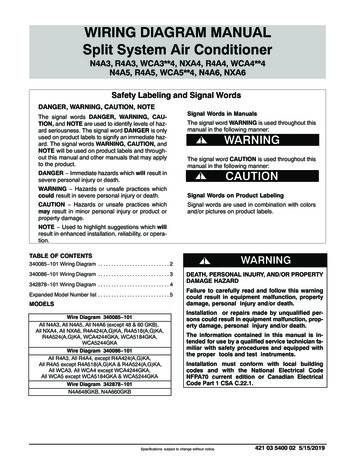
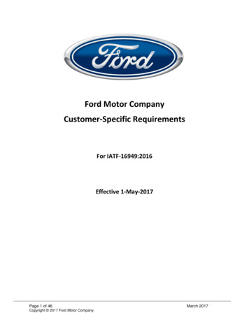
York SystemWiring DiagramYZHAVGMV2-STAGE HEAT PUMPSINGLE PIECE VARIABLE SPEED AIR HANDLERTWO PIECE VARIABLE SPEED AIR HANDLERIndexVision Pro8000VARIABLE SPEEDAIR OWHTAuxLOptionalRHEAT door Optional SensorHUMBLUY2/YGRYW2EGCBRNW1GRNBSY2 OUTW2 OUTW1 OUTGNOTES:If 10-wires between the Air Handler and the Heat Pump is not possible W1 and W2 can be combined at the AHwith a jumper eliminating W2 out and staged electric heat.X/L can be eliminated as the fault codes can be retrived from the board.Please call for more detailed instructions if the number of wires is an issue.Critical Installation Set up on Thermostat0170 12 (Tells the stat its operating 3 heat and 2 cool stages)Critical Installation Set up for Air Handler JumpersP5 Jumper Heat P6 Jumper Heat PumpSet Blower Speeds as Required for Proper CFM. P9 Heat,P10 Delay,P8 Cool,P11 Adj.Critical Installation Set up for Heat Pump JumpersHot Heat Pump ON/OFF (optional) Y2 Lock ON/OFF (Optional) Switch Point 35º is Factory DefaultBP (balance point) 35º is factory setting, but should be set to job specific temperatureLTCO (Low Temperature Cut Out) ON is factory Setting, this does not have to move unless requiredCompressor Delay Change to on for delay when going into and out of defrostWD 1
York SystemWiring DiagramsYZH2-STAGE HEAT PUMPAVGSINGLE PIECE VARIABLE SPEED AIR HANDLERMVTWO PIECE VARIABLE SPEED AIR HANDLERHONEYWELL 9000 IAQ THERMOSTATTOTHERMOSTATIndexIAQ 9000VARIABLE SPEEDAIR HANDLERYTH9421C1002HEAT RPURREDRCY1Y2OWX/LRBSGRHHUMBLUY2/YGRYW2Aux 2GCBRNW1GRNBSY2 OUTW2 OUTW1 OUTGNOTES:If 10-wires between the Air Handler and the Heat Pump is not possible W1 and W2 can be combined at the AHwith a jumper eliminating W2 out and staged electric heat.X/L can be eliminated as the fault codes can be retrived from the board.Please call for more detailed instructions if the number of wires is an issue.Critical Installation Set up on Thermostat#172, CHANGE TO 2(tells stat the system in a Heat Pump)#174, CHANGE TO 2(tells stat number of cooling stages)#176, CHANGE TO 3(tells stat number of heating stages)#200, CHANGE TO 0(tells stat back up heat is electric)Critical Installation Set up for Air Handler JumpersP5 Jumper Heat P6 Jumper Heat PumpSet Blower Speeds as Required for Proper CFM. P9 Heat,P10 Delay,P8 Cool,P11 Adj.Critical Installation Set up for Heat Pump JumpersHot Heat Pump ON/OFF (optional) Y2 Lock ON/OFF (Optional) Switch Point 35º is Factory DefaultBP (balance point) 35º is factory setting, but should be set to job specific temperatureLTCO (Low Temperature Cut Out) ON is factory Setting, this does not have to move unless requiredCompressor Delay Change to on for delay when going into and out of defrostWD 2
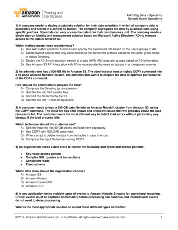
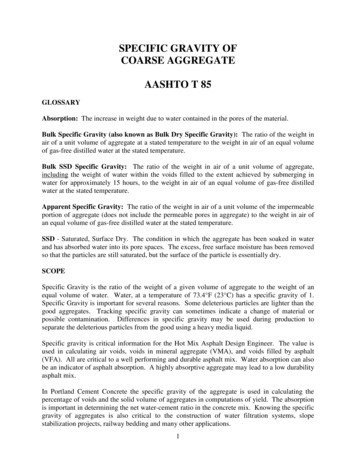
York SystemWiring DiagramsYZHYP9C2-STAGE HEAT PUMP95% MODULATING VARIABLE SPEED GAS FURNACEIndexVision Pro8000VARIABLE SPEEDGAS FURNACETH8321U1006COptionalYBLKCY1RCLo CompERINDOOR ACOILBSGHI CompBSBLUY/Y2Y2 OUTW2 door Optional SensorY2ORGORS1Y1BLU/YELAuxLCYELY2OHEAT PUMPCONTROLW1 OUTG* OPTIONAL BONNET SENSORNOTES:If 10-wires between the Air Handler and the Heat Pump is not possible W1 and W2 can be combined at the AHwith a jumper eliminating W2 out and staged electric heat.X/L can be eliminated as the fault codes can be retrived from the board.Please call for more detailed instructions if the number of wires is an issue.Critical Installation Set up on Thermostat0170 12 (Tells the stat system is 3 heat stages and 2 cool stages0200 1 (Tells stat back up is fossil fuel)0210 1 (Tells stat fossil fuel kit is external)Critical Installation Set up on Furnace JumpersJ19 Zone Control Y/N(optional) J22 Heat Pump YESSet Blower Speeds as Required for Proper CFM. J9 Cool, J16 Adj, J15 DelayCritical Installation Set up for Heat Pump JumpersHot Heat Pump ON/OFF (optional) Y2 Lock ON/OFF (Optional)Switch Point 35º is Factory DefaultF Fuel ONBP (balance point) 35º is factory setting, but should be set to job specific temperatureLTCO (Low Temperature Cut Out) ON is factory Setting, this does not have to move unless requiredCompressor Delay Change to on for delay when going into and out of defrostWD 3*
York SystemWiring DiagramsYZH2-STAGE HEAT PUMPYP9C95% MODULATING VARIABLE SPEED GAS FURNACEHoneywell 9000 IAQ ThermostatTOTHERMOSTATIndexIAQ 9000VARIABLE SPEEDGAS FURNACEYTH9421C1002HEAT o CompS1HI CompS2Y/Y2RINDOORA-COILBSGBSBLUY2 OUTW2 1 OUTG* OPTIONAL BONNET SENSORNOTES:If 10-wires between the Air Handler and the Heat Pump is not possible W1 and W2 can be combined at the AHwith a jumper eliminating W2 out and staged electric heat.X/L can be eliminated as the fault codes can be retrived from the board.Please call for more detailed instructions if the number of wires is an issue.Critical Installation Set up on Thermostat#172, CHANGE TO 2(tells stat the system in a Heat Pump)#174, CHANGE TO 2(tells stat number of cooling stages)#176, CHANGE TO 3(tells stat number of heating stages)#200, CHANGE TO 1(tells stat back up heat is electric)#210, CHANGE TO 1(tells stat external fossil fuel kit)Critical Installation Set up on Furnace JumpersJ9 Zone Control Y/N (optional)J22 Heat Pump YESSet Blower Speeds as Required for Proper CFM. J9 Cool, J16 Adj, J15 DelayCritical Installation Set up for Heat Pump JumpersHot Heat Pump ON/OFF (optional) Y2 Lock ON/OFF (Optional)Switch Point 35º is Factory DefaultF Fuel ONBP (balance point) 35º is factory setting, but should be set to job specific temperatureLTCO (Low Temperature Cut Out) ON is factory Setting, this does not have to move unless requiredCompressor Delay Change to on for delay when going into and out of defrostWD 4*
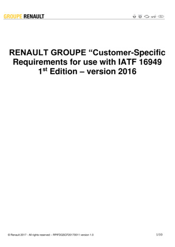
York SystemWiring DiagramsYZHTM9XTM8X2-STAGE HEAT PUMPGas FurnaceGas FurnaceIndexVision Pro8000TH8321U1006TM9XGas FurnaceCCYY1HEAT PUMPCONTROLBLKCYELY1BLU/YELY2Y2ORGOWHTPUR - r Optional SensorY2 OUTGRYW2 OUTBRNWGRNBSBLUY2/YEGWRRCS1OW1 OUTG* OPTIONAL BONNET SENSORNOTES:If 10-wires between the Air Handler and the Heat Pump is not possible W1 and W2 can be combined at the AHwith a jumper eliminating W2 out and staged electric heat.X/L can be eliminated as the fault codes can be retrived from the board.Please call for more detailed instructions if the number of wires is an issue.Critical Installation Set up on Thermostat0170 12 (Tells the stat system is 3 heat stages and 2 cool stages0200 1 (Tells stat back up is fossil fuel)0210 1 (Tells stat fossil fuel kit is external)Critical Installation Set up on Furnace JumpersP4 Jumper Blower Off Delay P7 Jumper Fan Speed Contionus FanSet motor speeds as required for proper air flowCritical Installation Set up for Heat Pump JumpersHot Heat Pump ON/OFF (optional) Y2 Lock ON/OFF (Optional) Switch Point 35º is Factory DefaultBP (balance point) 35º is factory setting, but should be set to job specific temperatureLTCO (Low Temperature Cut Out) ON is factory Setting, this does not have to move unless requiredCompressor Delay Change to on for delay when going into and out of defrostWD 5
York SystemWiring DisgramsYZH2-STAGE HEAT PUMPTM9XGas FurnaceTM8XGas FurnaceHONEYWELL 9000 IAQ THERMOSTATTOTHERMOSTATIndexIAQ 9000TM9XGas FurnaceYTH9421C1002HEAT PUMPCONTROL123CCYY1BLKYELBLU/YELY2ORGOWHTPUR - 2/YAux 2GCBRNWGRNBSY2 OUTW2 OUTW1 OUTGNOTES:If 10-wires between the Air Handler and the Heat Pump is not possible W1 and W2 can be combined at the AHwith a jumper eliminating W2 out and staged electric heat.X/L can be eliminated as the fault codes can be retrived from the board.Please call for more detailed instructions if the number of wires is an issue.Critical Installation Set up on Thermostat#172, CHANGE TO 2(tells stat the system in a Heat Pump)#174, CHANGE TO 2(tells stat number of cooling stages)#176, CHANGE TO 3(tells stat number of heating stages)#200, CHANGE TO 1(tells stat back up heat is fossil fuel)#210, CHANGE TO 1(tells stat fossil fuel is controlled external)Critical Installation Set up for Furnace JumpersP4 Jumper Blower Off Delay P7 Jumper Fan Speed Contionus FanSet motor speeds as required for proper air flowCritical Installation Set up for Heat Pump JumpersHot Heat Pump ON/OFF (optional) Y2 Lock ON/OFF (Optional) Switch Point 35º is Factory DefaultBP (balance point) 35º is factory setting, but should be set to job specific temperatureLTCO (Low Temperature Cut Out) ON is factory Setting, this does not have to move unless requiredCompressor Delay Change to on for delay when going into and out of defrostWD 6
York SystemWiring DiagramsYZF1-STAGE HEAT PUMP - 1.5 - 4 TonAVGMVSINGLE PIECE VARIABLE SPEED AIR HANDLERTWO PIECE VARIABLE SPEED AIR HANDLERIndexVision Pro8000VARIABLE SPEEDAIR LOptionalRHEAT tdoor Optional SensorHUMBLUY/Y2GRYW2ECGRNBRNW1BSY2 OUTW2 OUTW1 OUTGNOTES:If 10-wires between the Air Handler and the Heat Pump is not possible W1 and W2 can be combined at the AHwith a jumper eliminating W2 out and staged electric heat.X/L can be eliminated as the fault codes can be retrived from the board.Please call for more detailed instructions if the number of wires is an issue.Critical Installation Set up on Thermostat0170 7 (tells the stat it's operating at 2 heat and 1 cool stage as a heat pump)Critical Installation Set up for Air Handler JumpersP5 Jumper Heat P6 Jumper Heat Pump Set Blower Speeds as Required for Proper CFMSet Blower Speeds as Required for Proper CFM. P9 Heat,P10 Delay,P8 Cool,P11 Adj.Critical Installation Set up for Heat Pump JumpersHot Heat Pump ON/OFF (optional) Y2 Lock ON/OFF (Optional)BP (balance point) 35º is factory setting, but should be set to job specific temperatureLTCO (Low Temperature Cut Out) ON is factory Setting, this does not have to move unless requiredCompressor Delay Change to on for delay when going into and out of defrostWD 7
York SystemWiring DiagramsYZF!-STAGE HEAT PUMP 1.5 - 4 TonAVGSINGLE PIECE VARIABLE SPEED AIR HANDLERMVTWO PIECE VARIABLE SPEED AIR HANDLERHONEYWELL 9000 IAQ THERMOSTATTOTHERMOSTATIndexIAQ 9000VARIABLE SPEEDAIR HANDLERYTH9421C1002HEAT RPURREDRCY1Y2OWX/LRBSGRHHUMBLUY2/YGRYW2Aux 2GCBRNW1GRNBSY2 OUTW2 OUTW1 OUTGNOTES:If 10-wires between the Air Handler and the Heat Pump is not possible W1 and W2 can be combined at the AHwith a jumper eliminating W2 out and staged electric heat.X/L can be eliminated as the fault codes can be retrived from the board.Please call for more detailed instructions if the number of wires is an issue.Critical Installation Set up on Thermostat#172, CHANGE TO 2(tells stat the system in a Heat Pump)#174, CHANGE TO 1(tells stat number of cooling stages)#176, CHANGE TO 2(tells stat number of heating stages)#200, CHANGE TO 0(tells stat back up heat is electric)Critical Installation Set up for Air Handler JumpersP5 Jumper Heat P6 Jumper Heat PumpSet Blower Speeds as Required for Proper CFMSet Blower Speeds as Required for Proper CFM. P9 Heat,P10 Delay,P8 Cool,P11 Adj.Critical Installation Set up for Heat Pump JumpersHot Heat Pump ON/OFF (optional) Y2 Lock ON/OFF (Optional) Switch Point 35º is Factory DefaultBP (balance point) 35º is factory setting, but should be set to job specific temperatureLTCO (Low Temperature Cut Out) ON is factory Setting, this does not have to move unless requiredCompressor Delay Change to on for delay when going into and out of defrostWD 8
York SystemWiring DiagramsYZFAHE1-STAGE HEAT PUMP - 1.5 - 4 TonSINGLE PIECE X13 AIR HANDLERVision Pro8000X13MULTI -TAPAIR HANDLERTH8321U1006COptionalYHEAT REDRRCS1S2GY2OWX/LRBSGBSIndoor/Outdoor Optional SensorY2 OUTW2ECY1GRNBRNW1W2 OUTW1 OUTGCritical Installation Set up on Thermostat0170 7 (tells the stat it's operating at 2 heat and 1 cool stage as a heat pump)Critical Installation Set up for Air Handler JumpersSet Blower Speeds as Required for Proper CFMNote: W2 only required if 13 KW and above.Critical Installation Set up for Heat Pump JumpersHot Heat Pump OFFY2 Lock ON/OFF (Optional as a consumer choice)BP (balance point) 35º is factory setting, but can be set to job specific temperatureLTCO (Low Temperature Cut Out) ON is factory Setting, this does not have to move unless requiredCompressor Delay Change to on for delay when going into and out of defrostWD 9
York SystemWiring DiagramsYZFMX1-STAGE HEAT PUMP - 1.5 - 4 TonTWO PIECE X13 AIR HANDLERVision Pro8000X13MULTI -TAPAIR HANDLERTH8321U1006COptionalHEAT alRPURX/LREDRRCS1S2GY1Y2OWX/LRBSGIndoor/Outdoor Optional SensorHUMBSGRYW2ECGRNBRNW1Y2 OUTW2 OUTW1 OUTGCritical Installation Set up on Thermostat0170 7 (tells the stat it's operating at 2 heat and 1 cool stage as a heat pump)0180 1 (Fan is controlled by thermostat)Critical Installation Set up for Air Handler JumpersP5 Jumper Heat P6 Jumper Heat PumpSet Blower Speeds as Required for Proper CFMCritical Installation Set up for Heat Pump JumpersHot Heat Pump OFFY2 Lock ON/OFF (Optional as a consumer choice)BP (balance point) 35º is factory setting, but can be set to job specific temperatureLTCO (Low Temperature Cut Out) ON is factory Setting, this does not have to move unless requiredCompressor Delay Change to on for delay when going into and out of defrostWD 10
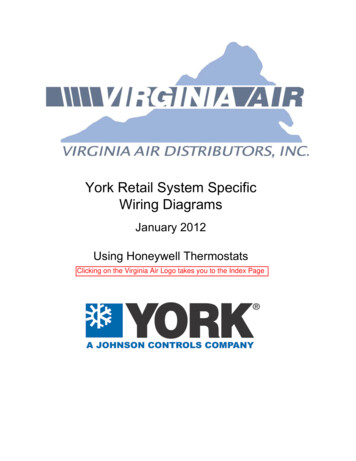
York SystemWiring DiagramsYZFTM9VTM8V1-STAGE HEAT PUMP - 1.5 - 4 Ton95% 2 Stage Variable Speed Gas Furnace80% 2 Stage Vairable SpeedGas FurnaceVision Pro8000Variable SpeedGAS FURNACEHEAT INDOORA-COILBSGIndoor/Outdoor Optional SensorEY/Y2Y2 OUTW2 OUTBRNWGRNBSBLUW2GIndexW1 OUTG* OPTIONAL BONNET SENSORNOTES:If 10-wires between the Air Handler and the Heat Pump is not possible W1 and W2 can be combined at the AHwith a jumper eliminating W2 out and staged electric heat.X/L can be eliminated as the fault codes can be retrived from the board.Please call for more detailed instructions if the number of wir
1 Stage HP 95% & 80% Single Stage X13 Gas Furnace HW VP 9000 WD18 . Terminals on the defrost control to connect bonnet sensor in the duel fuel mode Hum - Humidistat input. . (optional) Y2 Lock ON/OFF (Optional) Switch Point 35º is Factory Default. BP (balance point) 35º is factory