Transcription
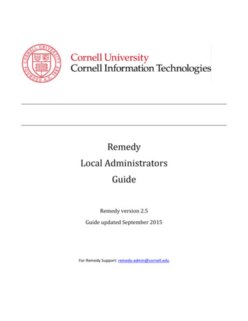
Home Security SystemA Cornell University ECE 476 Final ProjectbyChun-Pai Jimmy Hsieh & Yang Cao[Introduction][High Level Design][Program & Hardware][Result][Conclusions][Appendix]I n t r o d u c t i o nThis is a digital home security system with voice feature which can monitor room temperature, smoke, motion, andwindows & doors.The goal of this project is to utilize the after-market parts and build an integrated home security system. Besidestraditional magnetic switch equipped on doors and windows, we have also incorporated temperature sensor, smokedetectors, and motion sensor. Hence the security system will sound an alert when there is an attempt of break-inor if there is possible smoke or fire.The system is fully digital and also be fully customized. It incorporated a 16x2 LCD display with a 4x4 keypad. Eachsensor can be enabled or disabled, and alarm frequency and skim can also be chosen by users. We have alsoequipped a voice playback chip, and it will speak which sensor has gone wrong.Page 1 of 12
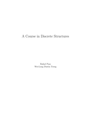
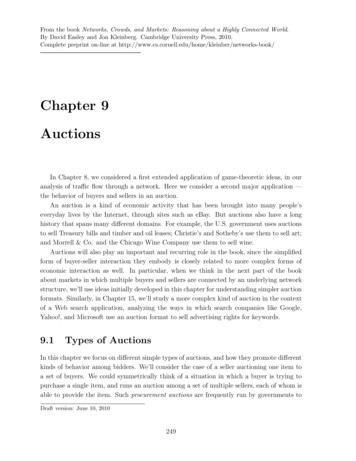
H i g hL e v e lD e s i g nProject IdeaThe idea of our project comes from lab 3 when we did a simple security system. However, that securitysystem is quite basic and only offers simple password lock. Hence we would like to enhance oursecurity system with different kinds of sensors. We have also browse some of the old final project andfound the "Phone Dialer" project from spring 2002. Originally, we were going to put Zarlink MT8880CDTMF transceiver chip, so it will dial a desire number that user specify. When the phone connected, wewill use Winbond ISD1420 voice record and playback chip to play pre-recorded voice signal. However,due to the lack of the phone jack in the lab, plus the majority of the Cornell campus has digital phoneline instead of analog phone line, we decided to put away this idea. Since ISD1420 chip has address bitfeature, we decided to make our system playback certain pattern of voice when the system goes intoalert status.Logical StructureThe logical structure of ourdesign is shown in the blockdiagram on the right. Thecentral system will handleall the sensors and keypadinput, output information toLCD screen, indicate systemstatus on LED, and makebuzz or voice alarm.Hardware & Software TradeoffsThe IR motion sensor is quite inexpensive ( 5.99 dollars for the one we got), so we also decided to buyit instead of building one on our own. We also acquire one of the smoke detector from home. This isthe very basic version and will sound the alarm when the smoke is detected.Page 2 of 12
Besides some necessary capacitor and resistor connections to the ISD1420 chip, the majority of ourproject is based on our software. This is mainly because our system if fully customizable and has quitea lot of features. It need to monitors all the sensor, and time the appropriate seconds in order to playcertain voice pattern (ex. "Temperature, smoke error, please " "Door or window error, please ")depending on which sensor goes wrong. It also need to handle the user interface via keypad and LCDscreen. All of these are programmed in our software.StandardsThe 16x2 LCD we use has standard 16 pin connection (pin 15 and 16 for LED backlit power). Thekeypad is also standard 4x4 which has 8 pin connector. The smoke detector is powered by standard Eblock 9V battery. The motion sensor is powered by 2 AAA 1.5V battery in serial.Existing Patents, Copyrights and TrademarksThe magnetic contact switch is manufactured by SECO-LARM? The motion detector is manufactured bySPY GEAR. The smoke sensor is a little bit hard to identify because we do not have the original box, butwe believe it manufactured by FAMILY GARD?P r o g r a m&H a r d w a r eD e s i g nProgram DetailThe hardest part of the program is timing. When any sensor goes wrong, the program will wait forcertain seconds (set by user), and then make ISD1420 chip play back the desired voice pattern wewant. Originally, we though we can just output the appropriate address bit and then make the chipplay, however, later on we discovered there is a THOLD in the ISD1420 chip that we need to take careof, otherwise it will reference to the previous address bits. The voice playback chip does not have avery fast internal clock, so we have to manually use the delay function in our program after we set theaddress bits, and then make the chip play. Although using the delay function is somehow undesirable,however, we have implemented our program such that this delay will not cause any error in oursoftware.Besides, we also need to implement the keypad function so it acts accordingly when the LCD isdisplaying certain menu. This is not very difficult but we have to take care of all the possiblecircumstances. We have 12 submenus in our system. Set temp define the lowest temperature allowedbefore sounding the alarm (70 120F, with step size of 1F). The Sec. Allow is the time in second beforethe voice alarm goes off (0 30sec, with step size of 2 seconds).1.Enable System2.(*)Temp Sensor3.(*)Mot. Sensor4.(*)Smk. Sensor5.(*)Mag. Switch6.Set Temp: 100F7.(*)Voice Alarm8.(*)Buzz Alarm9.New Pswd:A.Buzz Freq: 7B.Buzz Skim: 3C.Sec. Allow: 10We also have simple de-bounce feature for our keypad, and it will sound a buzz when you press anykey (if you HOLD a key but buzz will only sound once). Although the de-bounce function is as easy asPage 3 of 12
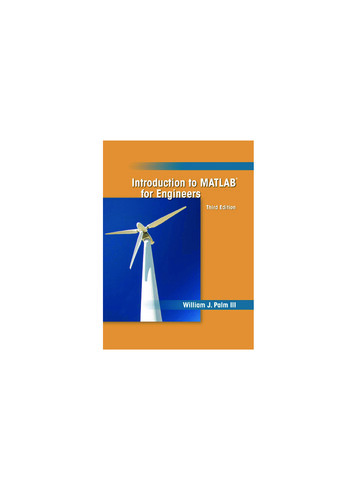
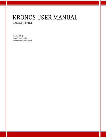
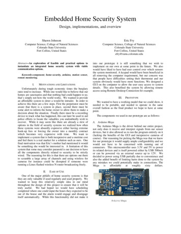
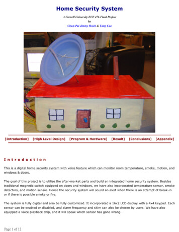
few lines, it takes a while to think about the logic and how to actually implement it. Also we implementthe backspace feature so that when use enter a wrong password, this key can be used to delete theprevious entered number. Also just a quick note, our password is masked on LCD for a safer purpose.Hardware DetailThe first sensor we have is the temperature sensor. Since we implemented a digital thermometer in lab5, we decided to use the same circuit. So we incorporated National Semiconductor LM34 temperaturesensor, with National Semiconductor LMC7111 OpAmp chip to amplifier our output voltage going intoADC. The final connection of our circuit look like the following.The second sensor we have is the motion sensor. Although we do not have the diagram of the circuit (ithas some IC components), we discovered there are few NPN transistors in the circuit. NPN transistorsare like switches, so it is obvious these are used enable the original buzzer on the circuit. Hence wetook the base pin together with ground to connect to our ADC pin input. If the voltage exceed VTH(threshold voltage), we know the alarm goes off.The third sensor we have is the smoke detector. The smoke detectors mostly equipped withpiezoelectric buzzer, which has F (feed back), C (main electrode), M (metal plate) three pins.Piezoelectric buzzer has an internal crystal and will sound if small current is applied (voltage drop).Hence we took out the piezoelectric buzzer and connect the F pin into our ADC input. When the sensorgoes off, the voltage will go high.The final sensor we have is the magnetic switches. It is normally closed. So when the switch is rightnext to each other, the resistance is zero. When the switch is separated, the resistance will becomeinfinity as if it’s disconnected. So we drive the switch with an 10K pull-up resistor, and connect theoutput to the ADC. Since we have two magnetic switches, we decided to build a simple AND/OR gateby using 1 74LS00 chip. There are four NAND gates in 74LS00, and if we connect two of NAND gate inparallel with their input signal to another NAND gate, we will get as if there are 2 AND gate in parallelwith their signals to an OR gate. The diagram can be found in our appendix.The 4x4 keypad has the layout like the table on the right. The - and buttons next to 0 can increase numbers in the submenu, such as time orfrequency. the UP and DOWN button next to 3 and 6 will navigate themenu. BK is backspace while entering the password. EN is enter and isused do enable/disable menu item or enable the system.123ˆ456ˇ789BK-0 ENReference DesignThe Winbond ISD1420 voice record and playback chip also requires external resistors and capacitors.We build the circuit from the reference circuit on ISD1420 specification sheet. The modification we haveis to connect the address bit to our PORTB on our MCP, and PLAYL to our pin 6 in PORTA of our MCP.The specification of this chip can be downloaded from the appendix. In addition, we also learn someinformation about piezoelectric buzzer from this website .Page 4 of 12
R e s u l to ft h eD e s i g nSpeed of ExecutionThe speed of the execution is work very well. In the beginning the system will boot up with defaultpassword 1234. The user can now navigate through our menu, and enable or disable each type ofsensor. If a particular sensor is enabled, the LCD screen will output a * symbol before the sensorname. User can also set the alert temperature, enable/disable voice or buzzer alarm, and even specifythe ring tone and frequency of the buzzer alarm and the time before voice alarm goes off. The buttonde-bounce scheme also works fine so users can navigate through the menu and use the keypadperfectly.AccuracyAfter the user enables the security system, the green status LED will lid to indicate the system status.User can now enter proper password to unlock the system. If any sensor goes wrong, the LCD willoutput ERROR and with proper initial for the sensor (T for temperature, M for motion, S for smoke, Dfor door or window magnetic switch). The red led light be will flashing at 4Hz to indicate such event. Ifthe buzz alarm is enable, it will sound the tone that user choose. If the voice alarm is enabled, it willwait for few seconds (user specified), if the system is still not locked, then it will start playing voice toindicate which sensor goes wrong. (For example, "Temperature Error, please check and unlock thesecurity system.") If another sensor goes wrong after that, the system will also act accordingly andindicate that in the voice alert in addition to the LCD screen. ("Temperature Motion Error, please checkand unlock the security system.")SafetyAs soon as user enters the correct password, the system will be unlocked and the buzzer and voiceplayback will stop. The user can now navigate through our menu and make any changes in thesettings.There are two kinds of smoke detectors, ionization chamber and photoelectric smoke detectors.Ionization chamber one is more popular due to its low cost. Our smoke detector from home also has anionization chamber. However, this kind of smoke detector has a small amount of radioactive material(americium-241), which has a half-life of 432 years (alpha decay). We have checked the specificationof such radioactive element and government web pages regarding to such kind of material. We havefound such radiation is relatively small as long as we do not inhale or swallow it. The exposures isrelatively weak so as long as we are not in touch of it all the time, it is relatively safe to operate thesmoke e alarm.htmUsabilityOur home security system is very practical. It can be used not only in the home environment but alsoin a business environment too. It can monitor the surrounds to not only protect our properties but alsoour lives. Besides, it can be highly customized to suit each one's need and preference. So our securitysystem is very useful for us as well as other people. We believe every house in the world should equiptPage 5 of 12
a security system like the one we design.C o n c l u s i o n sExpectation and ImprovementThe result of our design has met our expectation, in which every sensor is working and will soundspecific alarm when the system goes into alert status. The keypad and LCD also offer great interfaceand users can be familiar with our system in less than few seconds.If we have chance to design this project again, we will add a phone dialer chip like the Zarlink MT8880Cwe mentioned before. By doing so, we can make sure if no one is at home or if no one is around thearea, someone else can be notified to take immediate action. In addition, we feel like our PORTB is alittle bit wasted. We only have 4 output patterns but we are using all 8 pins. Next time we will use 74LSseries chip together with only 2 output pins from MCP, so together we can save 6 I/O pins. Besides, wewill like to have another small microcontroller at a higher frequency, so we can output our buzz alarmat a higher frequency tone.Intellectual PropertyBesides the reference circuit from ISD1420 chip specification, reference keypad decode scheme fromlab 3, and temperature sensor circuit from lab 5, we have designed and coded everything on our own.There is no code from public domain, and we did not reuse any code from the previous lab (we doreference, but not copy). Because we are using two pre-built sensor circuits (motion and smokesensor), we feel like we should not pattern our whole design. However, if we take out these two partsand only have these “inputs,” we definitely have opportunity to pattern our design.Ethical ConsiderationsReference to IEEE Code of Ethics, we have try our best effort to meet all requirements. Here are thefew examples.1. To accept responsibility in making engineering decisions consistent with the safety, health andwelfare of the public, and to disclose promptly factors that might endanger the public or theenvironment.Our design kept safety as one of the top priorities. For example, we could have built the smokedetector circuit on our own. However after we found out that it’s radioactive and it would be dangerousto expose the radioactive material; we decided to keep the smoking detector intact. We do not want toinjury anyone working around us or spread radioactive material in the air.2. To be honest and realistic in stating claims or estimates based on available data.From the beginning we were realistic about the specifications of our projects given time, knowledge,and economic constrains. Our final project closely follow
The goal of this project is to utilize the after-market parts and build an integrated home security system. Besides traditional magnetic switch equipped on doors and windows, we have also incorporated temperature sensor, smoke detectors, and motion sensor. Hence the security system will sound an alert when there is an attempt of break-in