Transcription
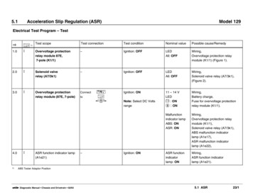
5.1Acceleration Slip Regulation (ASR)Model 129Electrical Test Program – TestOC 1)Test scopeTest connectionTest conditionNominal valuePossible cause/Remedy1.0IOvervoltage protectionrelay module 87E,7-pole (K1/1)–Ignition: OFFLEDAll: OFFWiring,Overvoltage protection relaymodule (K1/1) (Figure 1).2.0ISolenoid valverelay (A7/3k1)–Ignition: OFFLEDAll: OFFWiring,Solenoid valve relay (A7/3k1),(Figure 2).3.0IOvervoltage protectionrelay module (87E, 7-pole)ConnectIgnition: ON11 – 14 VLEDm : ONp : ONWiring,Battery charge,Fuse for overvoltage protectionrelay module (K1/1).Malfunctionindicator lampABS: ONASR: ONWiring,Overvoltage protection relaymodule (K1/1),Solenoid valve relay (A7/3k1),ABS malfunction indicatorlamp (A1e17),ASR malfunction indicatorlamp (A1e22),ASR functionindicatorlamp: ONWiring,ASR function indicatorlamp (A1e21).4.01)IASR function indicator lamp(A1e21)to–sCcNote: Select DC VoltsrangeIgnition: ONABS Tester Adaptor Positionb Diagnostic Manual Chassis and Drivetrain 02/935.1 ASR23/1
5.1Acceleration Slip Regulation (ASR)Model 129Electrical Test Program – TestOCTest scopeTest connectionTest conditionNominal valuePossible cause/Remedy5.0ICircuit 61 Start engineLEDWiring,Generator (G2).p : OFF6.0IStop lampswitch (S9/1) 7.02Solenoid valverelay (A7/3k1)Connect8.02ASR charging pump (M15)Voltage supplyb Diagnostic Manual Chassis and Drivetrain 02/93to20 w20 w20 wsCckcccIgnition: ONDepress brake pedalLEDn: ONWiring,Solenoid valve relay (A7/3k1),(Figure 2),Stop lamp switch (S9/1).Ignition: ON11 – 14 VLEDm : ONp : ONl: ONMalfunctionindicator lampABS: OFFASR: OFFWiring,Battery charge,Fuse for overvoltage protectionrelay module (K1/1).11 – 14 VWiring.Ignition: ONWiring,Overvoltage protection relaymodule (K1/1),Solenoid valve relay (A7/3k1),ABS malfunction indicatorlamp (A1e17),ASR malfunction indicatorlamp (A1e22).L 31L 22L 325.1 ASR23/2
5.1Acceleration Slip Regulation (ASR)Model 129Electrical Test Program – TestOCTest scopeTest connection9.03Solenoid valverelay (A7/3k1),Diode L1Connect10.011.012.013.03445Solenoid valverelay (A7/3k1),Diode L2to20 wLeft front axle vehiclespeed sensor (L6/1)Internal resistanceConnectLeft front vehiclespeed sensor (L6/1)Insulation resistanceConnectRight front axle vehiclespeed sensor (L6/2)Internal resistanceConnectb Diagnostic Manual Chassis and Drivetrain 02/93tototoTest conditionNominal valuePossible cause/RemedysCcIgnition: ON0.4 – 1.5 VLEDm : ONp : ONWiring,Solenoid valve relay (A7/3k1).kcIgnition: ON0.4 – 1.5 VWiring,Solenoid valve relay (A7/3k1).sCbIgnition: ON1.1 – 2.3 k ]Wiring,Left front axle vehicle speedsensor (L6/1).sCbIgnition: ONPress button: o 20 k ]Left front axle vehicle speedsensor (L6/1).sCbIgnition: ON1.1 – 2.3 k ]Wiring,Right front axle vehicle speedsensor (L6/2).L 175.1 ASR23/3
5.1Acceleration Slip Regulation (ASR)Model 129Electrical Test Program – TestOCTest scopeTest connection14.05Right front axle vehiclespeed sensor (L6/2)Insulation resistanceConnectLeft rear axle vehiclespeed sensor (L6/3)Internal resistanceConnectLeft rear axle vehiclespeed sensor (L6/3)Insulation resistanceConnectRight rear axle vehiclespeed sensor (L6/4)Internal resisitanceConnectRight rear axle vehiclespeed sensor (L6/4)Insulation resistanceConnect15.016.017.018.06677b Diagnostic Manual Chassis and Drivetrain 02/93tototototoTest conditionNominal valuePossible cause/RemedysCbIgnition: ONPress button: o 20 k ]Right front vehicle speedsensor (L6/2).sCbIgnition: ON0.6 – 1.6 k ]Wiring,Left rear axle vehicle speedsensor (L6/3).sCbIgnition: ONPress button: o 20 k ]Left rear axle vehicle speedsensor (L6/3).sCbIgnition: ON0.6 – 1.6 k ]Wiring,Right rear axle vehicle speedsensor (L6/4).sCbIgnition: ONPress button: o 20 k ]Right rear axle vehicle speedsensor (L6/4).5.1 ASR23/4
5.1Acceleration Slip Regulation (ASR)Model 129Electrical Test Program – TestOCTest scopeTest connection19.08Left front axle solenoidvalve (A7/3y1)Internal resistanceConnectRight front axle solenoidvalve(A7/3y2)Internal resistanceConnectLeft rear axle solenoidvalve (A7/3y3)Internal resistanceConnectRight rear axle solenoidvalve (A7/3y4)Internal resistanceConnect20.021.022.09I0IIb Diagnostic Manual Chassis and Drivetrain 02/93totototoTest conditionNominal valuePossible cause/RemedysCbIgnition: OFFPress button: o4–6]Wiring,ABS/ASR hydraulic unit (A7/3),(Figure 3).sCbIgnition: OFFPress button: o4–6]Wiring,ABS/ASR hydraulic unit (A7/3),(Figure 3).sCbIgnition: OFFPress button: o4–6]Wiring,ABS/ASR hydraulic unit (A7/3),(Figure 3).sCbIgnition: OFFPress button: o4–6]Wiring,ABS/ASR hydraulic unit (A7/3),(Figure 3).5.1 ASR23/5
5.1Acceleration Slip Regulation (ASR)Model 129Electrical Test Program – TestOCTest scopeTest connection23.04Left front axle vehiclespeed sensor (L6/1)VoltageConnect24.025.088Left front axle solenoidvalve (A7/3y1)Pressure retentionLeft front axle solenoidvalve (A7/3y1)Pressure reductionb Diagnostic Manual Chassis and Drivetrain 02/93tosCfRaise vehicleIgnition: ONTurn wheel atapproximately onerevolution/second.sVehicle raisedIgnition: ONTurn wheel atapproximately onerevolution/second.Press switch: “P “Apply brake pedal.remainsconnectedsremainsconnectedTest conditionVehicle raisedIgnition: ONApply brake pedal.Press switch: “PØ“Turn wheel atapproximately onerevolution/second.Nominal value0.1V LEDm: ONp: ONl: ONn: ONPossible cause/RemedyExcessive wheel bearing play,open circuit or wires connectedincorrectly,Left front axle vehicle speedsensor (L6/1).Brake lines on hydraulic unitreversed (Figure 3),Wires reversed,ABS/ASR hydraulic unit (A7/3).Wheel must beable to rotate.LEDm: ONp: ONl: ONq: ONn: ONReturn pressure pumprelay (A7/3k2),ABS/ASR hydraulic unit (A7/3)Wheel must beable to rotate.5.1 ASR23/6
5.1Acceleration Slip Regulation (ASR)Model 129Electrical Test Program – TestOCTest scope26.05Right front axle vehiclespeed sensor (L6/2)27.028.099Right front axle solenoidvalve (A7/3y2)Right front axle solenoidvalve (A7/3y2)b Diagnostic Manual Chassis and Drivetrain 02/93Test connectionsVehicle raisedIgnition: ONTurn wheel atapproximately onerevolution/second.sVehicle raisedIgnition: ONTurn wheel atapproximately onerevolution/second.Press switch: “P “apply brake ectedTest conditionVehicle raisedIgnition: ONApply brake pedal.Press switch: “PØ“Turn wheel atapproximately onerevolution/second.Nominal value0.1V LEDm: ONp: ONl: ONn: ONPossible cause/RemedyExcessive wheel bearing play,open circuit or wires connectedincorrectly,Right front axle vehicle speedsensor (L6/2).Brake lines on hydraulic unitreversed (Figure 3),Wires reversed,ABS/ASR hydraulic unit (A7/3).Wheel must beable to rotate.LEDm: ONp: ONl: ONq: ONn: ONReturn/pressure pumprelay (A7/3k2) (Figure 2),ABS/ASR hydraulic unit (A7/3).Wheel must beable to rotate.5.1 ASR23/7
5.1Acceleration Slip Regulation (ASR)Model 129Electrical Test Program – TestOCTest scope29.06Left rear axle vehiclespeed sensor (L6/3)Voltage30.031.0I0IILeft rear axle solenoidvalve (A7/3y3)Left rear axle solenoidvalve (A7/3y3)b Diagnostic Manual Chassis and Drivetrain 02/93Test connectionNominal valuePossible cause/RemedysVehicle raisedIgnition: ONTurn wheel atapproximately onerevolution/second.sVehicle raisedIgnition: ONTurn wheel atapproximately onerevolution/second.Press switch: “P “apply brake pedal.LEDm: ONp: ONl: ONn: ONWheel must beable to rotate.Brake lines on hydraulic unitreversed (Figure 3),Wires reversed,ABS/ASR hydraulic unit (A7/3).sVehicle raisedIgnition: ONApply brake pedal.Press switch: “PØ“Turn wheel atapproximately onerevolution/second.LEDm: ONp: ONl: ONq: ONn: ONWheel must beable to rotate.Return/pressure pumprelay (A7/3k2) (Figure 2),ABS/ASR hydraulic unit ectedTest condition0.1V Open circuit or wires connectedincorrectly,left rear axle vehicle speedsensor (L6/3).5.1 ASR23/8
5.1Acceleration Slip Regulation (ASR)Model 129Electrical Test Program – TestOCTest scope32.07Right rear axle vehiclespeed sensor (L6/4)33.034.0IIIIRight rear axle solenoidvalve (A7/3y4)Right rear axle vehiclespeed sensor (A7/3y4)b Diagnostic Manual Chassis and Drivetrain 02/93Test connectionsVehicle raisedIgnition: ONTurn wheel atapproximately onerevolution/second.sVehicle raisedIgnition: ONTurn wheel atapproximately onerevolution/second.Press switch: “P “apply brake ectedTest conditionVehicle raisedIgnition: ONApply brake pedal.Press switch: “PØ“Turn wheel atapproximately onerevolution/second.Nominal value0.1V LEDm: ONp: ONl: ONn: ONPossible cause/RemedyOpen circuit or wires connectedincorrectly,left rear axle vehicle speedsensor (L6/4).Brake lines on hydraulic unitreversed (Figure 3),Wires reversed,ABS/ASR hydraulic unit (A7/3).Wheel must beable to rotate.LEDm: ONp: ONl: ONq: ONn: ONReturn/pressure pump relay(A7/3k2) (Figure 2),ABS/ASR hydraulic unit (A7/3).Wheel must beable to rotate.5.1 ASR23/9
5.1Acceleration Slip Regulation (ASR)Model 129Electrical Test Program – TestO35.036.037.0CTest scopeTest connectionSwitchover/solenoidvalve (A7/3y5)32wkb20ku20wkcSnow chain switch (ASR)with indicator (S76)Snow chain switch (ASR)with indicator (S76)b Diagnostic Manual Chassis and Drivetrain 02/93Test conditionNominal valuePossible cause/RemedyIgnition: OFF2–4]Wiring,ABS/ASR hydraulic unit (A7/3).Ignition: ONFunctionindicator in S76comes on.Wiring,Snow chain switch (ASR) withindicator (S76).ON: 1 VOFF: 11 – 14 VWiring,Snow chain switch (ASR) withindicator (S76).L 303Ignition: ONL 5 Operate switch (S76) onand off5.1 ASR23/10
5.1Acceleration Slip Regulation (ASR)Model 129Electrical Test Program – TestOCTest scope38.02Pressure switch (A7/3s1)Test connection20 wkcTest conditionNominal valuePossible cause/RemedyIgnition: ON0V(Pressurereservoir full)Wiring,ABS/ASR hydraulic unit (A7/3).L 8 Briefly open (maximum 2seconds) bleed connection“SP“ (Figure 3) onhydraulic unit (A7/3)according to workinstructions.39.08ASR charging pump (M15),return/pressure pumpmotor (A7/3m1)tosC33kuConnectBridge formaximumof 60seconds.b Diagnostic Manual Chassis and Drivetrain 02/93Ignition: ONPress switch:“P “(maximum of 60 seconds)3411 – 14 V(Signal topressurize).11 – 14 V to0VPumps can beheard running(running timeapproximately40 secondsuntil pressurereservoir is full).Wiring,ABS/ASR hydraulic unit (A7/3),33.5.1 ASR23/11
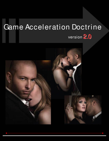
5.1Acceleration Slip Regulation (ASR)Model 129Electrical Test Program – TestP42-2044-13P42-2045-13Figure 2Figure 3A7/3ABS/ASR hydraulic unitA7/3A7/3k1Solenoid valve relayA7/3k2High-pressure/return pump relayABS/ASR hydraulic unitP07-2031-15AFigure 1K1/1Overvoltage protection relay module (87E, 7-pole)N4/1Electronic accelerator/cruise control moduleN30/1ABS/ASR control moduleb Diagnostic Manual Chassis and Drivetrain 02/935.1 ASR23/12
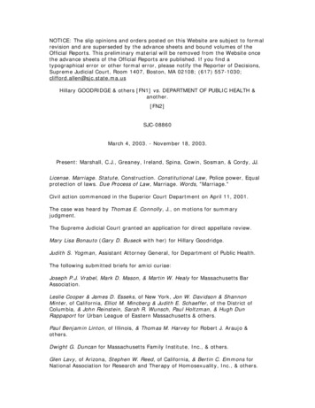
5.1Acceleration Slip Regulation (ASR)Model 129Electrical Test Program – TestP42-2046-13P42-2079-13P54-2039-13Figure 4Figure 5Figure 6M15ABS-adapter plugX4/10Terminal block (terminal 30/30Ue/61e/87L)X62/6Right front axle vehicle speed sensor connectorASR charging pump(component compartment)b Diagnostic Manual Chassis and Drivetrain 02/935.1 ASR23/13
5.1Acceleration Slip Regulation (ASR)Model 129Electrical Test Program – TestP42-2053-13AP54-2058-13P42-2050-13Figure 7Figure 8Figure 9L6/1Left front axle vehicle wheel sensorX62/7X62/15X62/14Left front axle vehicle speed sensor connectorLeft front axle vehicle speed sensor connector(component compartment)Right front axle vehicle speed sensor connector(axle spindle)(axle spindle)b Diagnostic Manual Chassis and Drivetrain 02/935.1 ASR23/14
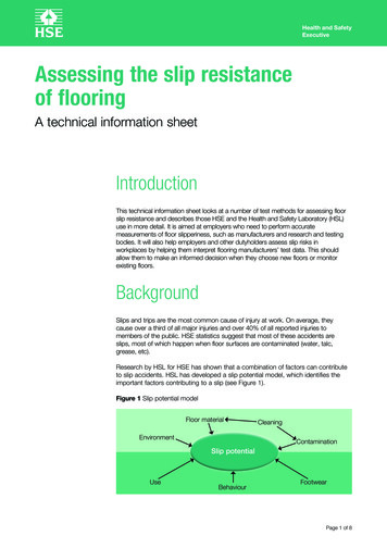
5.1Acceleration Slip Regulation (ASR)Model 129Electrical Test Program – TestP54-2060-13BP42-2056-13P54-2043-13AFigure 10Figure 11Figure 12X62/1Left rear axle vehicle wheel sensor connectorX62/8X30/1X62/2Right rear axle vehicle speed sensor connectorRear axle multiple circuit junction connectorMulti-function block connector(2-pole)b Diagnostic Manual Chassis and Drivetrain 02/935.1 ASR23/15
5.1Acceleration Slip Regulation (ASR)Model 129Electrical Test Program – TestP54-2080-13P42-2078-13Figure 13Figure 14X18/10Layout of connector X62/8Interior/ASR connector (8-pole)b Diagnostic Manual Chassis and Drivetrain 02/935.1 ASR23/16
5.1 Acceleration Slip Regulation (ASR) Model 129 Electrical Test Program – Test O C Test scope Test connection Test condition Nominal value Possible cause/Remedy 29.0 6 Left rear axle vehicle speed sensor (L6/3) Voltage remains connect ed s Vehicle raised Ignition: ON Turn wheel at approximately one revolution/second. 0.1V Open circuit or wires connected