Transcription
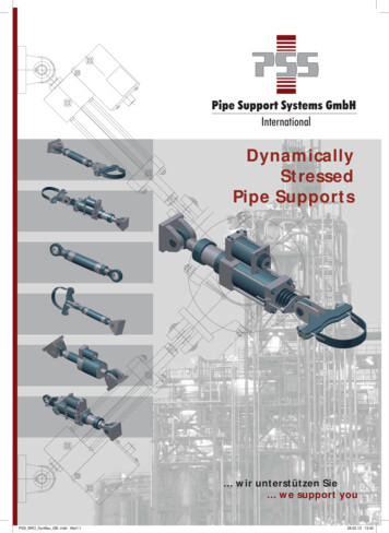
Pipe Support Systems GmbHInternationalDynamicallyStressedPipe Supports wir unterstützen Sie we support youPSS BRO DynBau GB-.indd Abs1:128.02.13 13:42
PSS Pipe Support Systems GmbH InternationalPipe Support Systems GmbHInternational. we area leading manufacturing companyspecialising in the field of pipe supportproducts and systems.PSS has over 35 years experiencein design, engineering and manufacturingof pipe hangers for power plants,chemical and petrochemical projects.Our design, manufacturing, R&D andmarketing departments are locatedin modern facilities in the cityof Neunkirchen.PSS BRO DynBau GB-.indd Abs1:2Our manufacturing operations arecarried out with the newest productionmachinery and test equipment and ourpersonnel employs the proven technologyrequired to make us your reliable partnerwho will truly meet your needs.PSS has a powerful and experienced teamof engineers, technicians, service andsales personnel at our Neunkirchen facilityas well as through our representatives andpartner companies worldwide.28.02.13 13:42
PSS Pipe Support Systems GmbH InternationalENGINEERING Design and Calculation of all Typesof Pipe Supports Detail Engineering PDMS Engineering. OUR QUALITY STANDARDSDIN EN ISO 9001KTA 1401SIEMENS QSP 4A Design of Special Pipe Supports Stress Analysis and Finite Element AnalysisPSS STANDARD SUPPORTSare designed in accordance with:. OUR PRODUCT RANGEDIN EN, VGB and SVDB Specifications Hydraulic Shock and Sway Suppressors(snubbers)BS3974, Part 1 Constant Hangers and Supports Variable Spring Hangers and Supports Pipe Clamps Sway StrutsKTA 3205.3ANSI B 31.1MSS SP 58 and MSS SP 69ASME Section III, Subsection NF Special Pipe Supports Accessories for Pipe HangersPSS INERNATIONAL PRODUCTS. OUR MAJOR MARKETSare worldwide present in more than 60 countriesin Europe, Asia, North- and South America, Africaand Oceania. Nuclear and Conventional Power Plants Refineries Platforms Oil, Gas and Chemical Process Plantsand Related Industries wir unterstützen Sie we support youPSS BRO DynBau GB-.indd Abs1:328.02.13 13:42
PSS Pipe Support Systems GmbH InternationalContent SummaryDynamically Stressed Pipe Supports1. Hydraulic Shock Suppressors and Vibration DampersGeneral Information on Hydraulic Shock Suppressors and Vibration Dampers (Snubbers)Application, FunctionConstruction and quality characteristicsDesign VariationsStandard settings and test values,Maintenance of hydraulic shock suppressors and vibration dampersTest Diagram for Hydraulic SnubbersTechnical dataAllowable loadsFigures without extension: Figures 200A, 200B, 202AFigures with extension: Figures 201A, 201B, 203AFigures 200A, 201AFigures 200B, 201BFigures 202A, 203ACalculation cold position, hot position2. ExtensionsExtension pieces for Hydraulic Shock and Sway SuppressorsTechnical dataExtension pieces, Fig. 201S, 201C and 201W3. Sway strutsGeneral Information on Sway strutsApplication, Construction and quality characteristics, Design VariationsTechnical dataFigure 211L Typ E1Figure 211L Typ E24. Weld-on bracketsGeneral Information on Weld-on bracketsTechnical dataFigure EHS 14S5. Dynamic load clamps4General Information on Dynamic load clampsTechnical dataDynamic three bolt clamp, Fig. 211RDynamic yoke clamp, EHS17DDynamic U-Bolt clamp, EHS18SDynamic Vertical clamp, Fig. 403DPSS BRO DynBau GB-.indd 2528323428.02.13 13:42
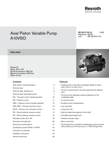
PSS Pipe Support Systems GmbH InternationalDynamically Stressed Pipe SupportsDynamically stressed pipe supports from PSS areused to support, restrain and suppress dynamicload events.This group consists of the following products: Hydraulic shock suppressorsand vibration dampers Sway struts Weld-on brackets Dynamic pipe clamps5PSS BRO DynBau GB-.indd Abs1:528.02.13 13:42
PSS Pipe Support Systems GmbH InternationalHydraulic Shock Suppressorsand Vibration Dampers1. Hydraulic Shock Suppressors and Vibration Dampers1.1 Application1.2 FunctionHydraulic shock suppressors and vibration dampersare components of great relevance to the technicalsafety of pipelines and system components, andare employed for the purpose of their protection.In the event of a dynamic load that causes thepiston to move faster than the locking velocity setby PSS (standard velocity 2 mm/s), the check valvecloses, the free flow of the silicon oil is impeded,and the shock suppressor absorbs forces. Whenthe pre-set force level is not attained, for instancewhen the direction of movement is reversed,the check valve opens up again. In the eventof a vibrating movement, both check valves openand close alternately, i.e. the shock suppressorabsorbs the same load in both tension andcompression directions. The bypass (or overflow)valve allows the piston to yield as far as thedefined nominal load.PSS hydraulic shock suppressors and vibrationdampers are employed to prevent damage toapparatuses, pipelines, pressure vessels, valvesand pumps, which can occur through suddenlyacting forces. This includes dynamic load eventswhich can occur during operation, such as waterhammer, pipe bursts or pressure surges causedby blowing off safety valves, as well as casesresulting from external events and conditions,such as earthquakes, explosions and wind load.Moreover, PSS hydraulic shock suppressors andvibration dampers can be employed in vibratingpipelines and system components where vibrationdamping is required.Conditions: Amplitude is greater than 0.5 mm Frequency is in the range 1-33HzBy employing hydraulic shock suppressorsand vibration dampers, it is possible to reducedynamic displacement amplitudes to a minimum.Movements due to temperature change are nothindered by hydraulic shock suppressors andvibration dampers.6PSS BRO DynBau GB-.indd Abs1:628.02.13 13:42
PSS Pipe Support Systems GmbH InternationalHydraulic Shock Suppressorsand Vibration Dampers1.3 Construction and qualitycharacteristicsThe PSS hydraulic shock suppressors and vibrationdampers have pressurized hydraulic systems thusallowing their installation in any position andorientation. The fluid level of the suppressorscan be easily and accurately verified though theposition of the piston rods as they relate to eachother.PSS hydraulic shock suppressors and vibrationdampers are of a modular construction.Modifications and alterations, which may berequired due to tight installation spaces or inorder to replace shock suppressors from othermanufacturers, can be implemented quickly bymodifying the standard components.at high frequencies in tension and compressiondirections. When the direction of movementchanges, the second valve can already react beforethe first valve has returned to its initial position.By employing modern, high-quality sealing andguide components, a service life of 40 years canbe expected from a PSS shock suppressors whenused in nuclear applications. Relevant simulationtesting with shock suppressors, Fig. 200A, havebeen conducted in association with the TÜVinstitute. Depending on the conditions in whichhydraulic shock suppressors and vibration dampersare employed, a maintenance-free period ofbetween ten and 25 years can be assured.Use conditions for PSS hydraulic shock absorbers and vibration dampersUnitWith hydraulic fluidnuclearWith hydraulic fluidstandardConstant operating temperature[ C]– 20 to 80– 50 to 80Short-term temperature*[ C]150150[Megarad]10020Ambient pressure, constant op.[bar]11Ambient pressure, short-term[bar]1010Solidification point[ C]– 40– 67Flashpoint[ C] 550600Ignition point[ C] 600 675Radiation dose, max.* max. 40h per year with max. cycle times of 1 hourA PSS hydraulic shock suppressor and vibrationdamper consists of two valve pairs, workingindependently and which are externally accessible.This allows the dampers to be optimised inaccordance with customer requirements on thetest bench (e.g. locking velocity, bleed rate).Even following installation, it is still possible tomodify the settings should this be required by theconditions at the installation site. By employingindependently functioning closing valves, PSShydraulic shock suppressors and vibration dampersare able to generate the force required for useThe following documents were taken into consideration in the dimensioning of PSS hydraulic shocksuppressors and vibration dampers:VGB Guidelines (Richtlinien)KTA 3205.3DIN 1050, DIN 4100BS 3974, Part 1ANSI B31.1MSS SP 58MSS SP 69SVDB Guidelines (Richtlinien)ASME Section III Subsection NF7PSS BRO DynBau GB-.indd Abs1:728.02.13 13:42
PSS Pipe Support Systems GmbH InternationalHydraulic Shock Suppressorsand Vibration Dampers1.4 Design VariationsPSS hydraulic shock suppressors and vibrationdampers are manufactured and available in thefollowing options:Standard designHousing components made of carbon steel withan extremely corrosion-resistant zinc-iron coating,15 μm.The piston rods are additionally coated with40 μm electroless nickel on all sides and the shaftwith 20 μm hard chrome.Low-temperature design down to -50 CHousing components are made of stainlesssteel 1.4301 and additionally coated with 15 μmelectroplated nickel.Piston rods made of materials suitable for useat low temperatures are additionally coated with40 μm electroless nickel on all sides and the shaftwith 20 μm hard chrome.The cylinder body is made of carbon steels,protected by a zinc-iron plating plus a paintingsystem according corrosive category C5-M(PSS-painting system PSS-6)Other material combinations and specialcoatings are available if requested by thecustomer.Furthermore, PSS offers special accessories, suchas bellows for protection against the build up ofhard ice deposits on the piston rods or to protectthe piston rods when employed in sandstormsor in installation areas with a high level of dirt.To prevent the installation length supplied by thecustomer from being altered during installation,PSS also offers a piston rod lock as an optionalaccessory. This can be combined with the pistonposition indicator (see images).Stainless steel designAll housing components, piston rods and jointheads are made of chloride-resistant steels,e.g. 1.4462 or 1.4404, with coating if required.Offshore designPiston rods and reservoir made of chlorideresistant stainless steels, e.g. 1.4462 or 1.4404,rod eyes supplied in material 1.4541.Hydraulic snubber with piston rod locking deviceand piston position indicatorStainless steel hydraulic snubberHydraulic snubberwith piston bellowsHydraulic snubber with piston rod locking device,piston position indicator and piston bellows8PSS BRO DynBau GB-.indd Abs1:828.02.13 13:42
PSS Pipe Support Systems GmbH InternationalHydraulic Shock Suppressorsand Vibration Dampers1.5 Standard settings and test valuesper KTA 3205.3 and VGB-R510L:Rolling resistance:max. 2% of nominal loadFriction:max. 2% of nominal loadResponse speed:2 – 6 mm/sPost-reaction speed:0,2 – 2,0 mm/sSliding rod distance Sa: 0,5 mm (non-rotating)Sliding rod distance Sb: amount 0.02 nominal displacement(force build-up peak-to-peak)Temperatures:max. operating temp. 80 CShort-term operating temp. for max. 3 hours 150 CDeflection perpendicular to bolt axis:max.: 70 Deflection in bolt axis:min.: 5 special settings on customer demands1.6 Maintenance of hydraulicshock suppressors and vibrationdampersPSS hydraulic shock suppressors and vibrationdampers are composed of metallic and organiccomponents. The metallic components are dimensioned in line with the various application designsto provide a service life that conforms with themaximum service life of a system (up to 40 years).The hydraulic fluid and seals are made of organiccomponents, which are subject to natural ageing.When used in extreme conditions, it is possiblethat these components age at an accelerated rate(constant vibration, high temperature, extremeradiation). Depending on the location and purposeof the hydraulic shock suppressors and vibrationdampers, the seals and hydraulic fluid should bechanged after 20 years at the latest.The operator of the system is responsible formaintaining the system components. However,PSS provides the following maintenancerecommendations that apply to hydraulic shocksuppressors and vibration dampers: Annual visual inspection of the shocksuppressors and checking of the positionof the reservoir piston rod (as long as thisis visible, there is sufficient hydraulic fluidin the shock suppressor). After a period of 10-15 years, a functionaltest of the individual shock suppressors isrecommended, to be performed on a hydraulictest bench. After 20 years at the latest, both the hydraulicfluid and the seals should be changed.PSS will be happy to supply you with a serviceplan compiled specifically for the system and theapplication of the hydraulic shock suppressors andvibration dampers.9PSS BRO DynBau GB-.indd Abs1:928.02.13 13:42
PSS Pipe Support Systems GmbH InternationalHydraulic Shock Suppressorsand Vibration DampersTest Diagram for Hydraulic SnubbersFigure No.:Size (inch):200ANominal travel (inch):6Nominal load (Newton):PSS works order number:30300010209Serial Number:5Customer:R8925N10Temperature ( C):Mark No.:211075Test ResultsBreakaway force (Newton)Friction force (Newton)Bleed rate ompression2005–1927– 18860,5– 0,5Response velocity (mm/s)Load at 5 Hz (Newton)Piston reaction travel (mm)tensioncompressiontensioncompressionSaSb3,9– 3,978272– 771390,54,4Measured strokeMeasured reservoir oil levelLeackage control127,7 mm63,0 mmokMiscellaneous10PSS BRO DynBau GB-.indd Abs1:1028.02.13 13:42
PSS Pipe Support Systems GmbH InternationalHydraulic Shock Suppressorsand Vibration Dampers1.7 Technical DataAllowable loads:cylinder-boresizeFigureinchFigure withextension1 x FNload case H* [kN]1,5 x FNload case HZ* (kN)1,7 x FNload case HS* [kN]A / B** Nominal loadC** EmergencyD** Faultet1/4, 1/2, 1200A, 200B201A, 201B812141 1/2200A, 200B201A, 201B1320222 1/2200A, 200B201A, 201B4568773 1/4200A, 200B201A, 201B781171334200A201A121182206
Special Pipe Supports Accessories for Pipe Hangers. OUR MAJOR MARKETS Nuclear and Conventional Power Plants Refi neries Platforms Oil, Gas and Chemical Process Plants and Related Industries . OUR QUALITY STANDARDS DIN EN ISO 9001 KTA 1401 SIEMENS QSP 4A PSS STANDARD SUPPORTS are designed in accordance with: DIN EN, VGB and SVDB Specifi cations BS3974, Part 1 KTA 3205.3 ANSI B 31.1 MSS SP .File Size: 2MBPage Count: 40
