Transcription
1.9-Liter TDI Enginewith Pump Injection(Pumpe Düse)Design and FunctionSelf-Study ProgramCourse Number 841303
Volkswagen of America, Inc.Service TrainingPrinted in U.S.A.Printed 10/2003Course Number 841303 2003 Volkswagen of America, Inc.All rights reserved. All information containedin this manual is based on the latestinformation available at the time of printingand is subject to the copyright and otherintellectual property rights of Volkswagen ofAmerica, Inc., its affiliated companies and itslicensors. All rights are reserved to makechanges at any time without notice. No partof this document may be reproduced,stored in a retrieval system, or transmittedin any form or by any means, electronic,mechanical, photocopying, recording orotherwise, nor may these materials bemodified or reposted to other sites withoutthe prior expressed written permission ofthe publisher.All requests for permission to copy andredistribute information should be referredto Volkswagen of America, Inc.Always check Technical Bulletins and theVolkswagen Worldwide Repair InformationSystem for information that may supersedeany information included in this booklet.Trademarks: All brand names and productnames used in this manual are trade names,service marks, trademarks, or registeredtrademarks; and are the property of theirrespective owners.
Table of ContentsIntroduction . 11.9-Liter TDI Engine with Pump Injection SystemEngine – Mechanics . 2Development of the 1.9-Liter TDI Engine with PumpInjection System, Technical Data – 1.9-Liter TDI Enginewith Pump Injection System, Trapezoidal Piston andConnecting Rod, Toothed Belt DriveFuel Supply . 8Fuel Supply System Overview, Fuel Pump,Distributor Pipe, Fuel Cooling SystemPump Injection System . 15Pump/Injectors, Design, Injection CycleEngine Management . 281.9-Liter TDI Engine EDC 16 System Overview,Sensors, ActuatorsGlow Plug System . 53Glow Plug SystemFunctional Diagram . 54EDC 16 Functional Diagram for 1.9-Liter TDI EngineService. 56Self-Diagnosis, Pump/Injector Adjustment, Special ToolsNew!Knowledge Assessment . 61Important/Note!The Self-Study Program provides you with informationregarding designs and functions.The Self-Study Program is not a Repair Manual.For maintenance and repair work, always refer to thecurrent technical literature.i
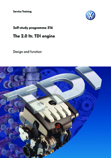
Introduction1.9-Liter TDI Engine withPump Injection SystemThe demands on the modern diesel enginefor increased performance and fueleconomy, and reduced exhaust emissionsand noise levels are growing constantly.Good fuel and air mixture preparation is akey factor in meeting these requirements.This calls for efficient injection systems thatproduce high injection pressures to ensurethat the fuel is well atomized. It is alsonecessary to precisely control the start offuel injection and the injection quantity.The pump injection system meetsthese requirements.In 1905, Rudolf Diesel came up with theidea of a pump/injector, combining theinjection pump and injector in one unitin order to dispense with high-pressurelines and achieve high injection pressures.At the time, however, he did not havethe technical means to put his ideainto practice.SSP304/032Diesel engines with mechanically controlledpump injection systems have been in usein ships and trucks since the 1950s.In association with Bosch, Volkswagen hassucceeded in developing a diesel enginewith a solenoid valve controlled pumpinjection system suitable for use inpassenger cars.The 1.9-liter TDI engine with the new pumpinjection system meets the stringentdemands for improved performance andcleaner emissions.With continuing advances like this one,Rudolf Diesel’s vision of “smoke- andodor-free exhaust gases” may one daybecome a reality.SSP209/0271
Engine – MechanicsDevelopment of the1.9-Liter TDI Engine withPump Injection SystemThe new 100 bhp (74 kW) 1.9-liter TDIengine with pump injection system wasdeveloped from the existing 109 bhp (81kW) 1.9-liter TDI engine with a distributorinjection pump and no intermediate shaft.The pump injection system comprises theonly significant difference between thetwo engines.This Self-Study Program concernsthe design and function of the new pumpinjection system, and the modificationsto the fuel system, engine managementsystem, and engine mechanicalcomponents to accommodate the system.A diesel engine with the pump injectionsystem has the following advantages overan engine with a distributor injection pump: Low combustion noise. Low fuel consumption. Clean emissions.SSP209/005 High efficiency.These advantages are attributable to: The high injection pressures of up to27,846 psi (192,000 kPa / 1,920 bar). Precise control of the injection cycle. The pre-injection phase.2
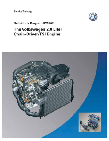
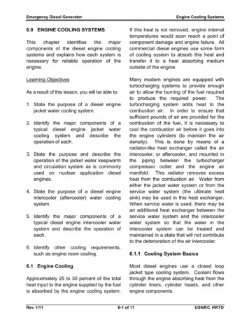
Engine – Mechanics Engine codeBEWlbs-ft NmhpkW221 30012190184 25010175148 2008060111 150604574 1004030372015 Displacement115.7 cu in (1,896 cm3) Bore3.13 in (79.5 mm) Stroke3.76 in (95.5 mm) Compression ratio19.0 : 1 Maximum power output100 bhp (74 kW) @ 4000 rpmTorque TypeFour-cylinder in-line engine with twovalves per cylinder500OutputTechnical Data –1.9-Liter TDI Engine withPump Injection System0100020003000Speed (rpm)40005000SSP209/006 Maximum torque177 lbs-ft (240 Nm) @ 1800 to 2400 rpm Engine managementEDC 16 Firing sequence1-3-4-2 Emission ControlBin 10 EPA Federal Emissions Concept,OBD II, catalytic converter, water-cooledEGR system3
Engine – MechanicsTrapezoidal Pistonand Connecting RodTo accommodate the higher combustionpressures in the 1.9-liter TDI engine withpump injection system than areencountered in the base engine, the pistonhub and the connecting rod eye aretrapezoidal in shape.SSP209/0074
Engine – MechanicsIn comparison with the conventionalparallelogram-shaped link between thepiston and connecting rod, the trapezoidalconnecting rod eye and piston hub have alarger contact surface area at the piston pinowing to their shape.Force Distribution in a Parallelogram-ShapedPiston and Connecting RodCombustion ForceContact SurfaceSSP209/008This distributes the combustion forces overa larger area and relieves the load on thepiston pin and connecting rod.Force Distribution in a Trapezoidal Pistonand Connecting RodContact SurfaceCombustion ForceSSP209/0095
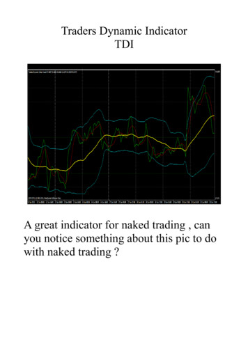
Engine – MechanicsToothed Belt DriveHigh pump forces are required to generatehigh injection pressures of up to 27,846 psi(192,000 kPa / 1,920 bar).These forces subject the components ofthe toothed belt drive to high loads.To relieve the load on the toothed belt,several modifications have been made. A vibration absorber integrated in thecamshaft gear reduces vibration inthe toothed belt drive. The toothed belt is about 0.20 inch(5 mm) wider than the toothed belt usedin the base engine. Higher forces can betransmitted by the larger surface area. A hydraulic tensioner keeps thetoothed belt evenly tensioned indifferent load states. Some of the teeth on the crankshafttiming belt gear have a larger gapclearance to reduce toothed belt wear.SSP209/089GapClearanceTo relieve the load on the toothed beltduring the injection cycle, the crankshafttiming belt gear has two pairs of teeth witha larger gap clearance than the other teeth.SSP209/886
Engine – MechanicsFunctionDuring the injection cycle, the highpumping forces exert a heavy load on thetoothed belt.The camshaft timing belt gear is sloweddown by the pumping forces. At the sametime, the combustion process speeds upthe crankshaft timing belt gear. The toothedbelt is stretched and the pitch is temporarilyincreased as a result.Because of the engine firing order, thisstretching process occurs at regularintervals and the same teeth on the timingbelt gear are in mesh with the toothed beltevery time.Deceleration ForcePitchNon-uniform tooth gap clearanceOn the 1.9-liter TDI engine with pumpinjection system, the crankshaft timing beltgear teeth have a larger gap clearance atthese points to compensate for the changein belt tooth pitch and thus reduce toothedbelt wear.Acceleration ForceSSP209/0917
Fuel SupplyFuel Supply System OverviewA mechanical fuel pump sucks the fuel outof the fuel tank through the fuel filter andpumps it along the supply line in thecylinder head to the pump/injectors.The fuel that is not required for injection isreturned to the fuel tank via the return linein the cylinder head, a fuel temperaturesensor, and a fuel cooler.Fuel Temperature Sensor G81 –Determines the temperature of thefuel in the fuel return line and sends acorresponding signal to the Diesel DirectFuel Injection Engine Control Module J248.Fuel Cooler – Cools the returning fuelto prevent excessively hot fuel frombeing routed back to the fuel tank.Fuel TankFuel Filter – Protects the injectionsystem against contamination andwear caused by particles and water.Non-Return Valve – Prevents fuelfrom the fuel pump flowing back intothe fuel tank while the engine is notrunning. It has an opening pressureof 2.9 psi (20 kPa / 0.2 bar).8
Fuel SupplyPressure Limiting Valve Bypass –If there is air in the fuel system,for example when the fuel tankis empty, the pressure limitingvalve remains closed. The air isexpelled from the system by thefuel flowing into the tank.Cylinder HeadFuel Return Line PressureLimiting Valve – Keeps thepressure in the fuel return lineat 14.5 psi (100 kPa / 1 bar).This maintains a forceequilibrium at the pump/injector solenoid valve needle.Restrictor – Located between thefuel supply line and the fuel returnline. Vapor bubbles in the fuel supplyline are separated through therestrictor into the fuel return line.Strainer – Collects vapor bubbles in thefuel supply line. These vapor bubbles arethen separated through the restrictorinto the return line.Fuel Pump Rotor – Pumps the fuel fromthe fuel tank through the fuel filter andthe fuel supply line in the cylinder headto the pump/injectors.Fuel Supply Line Pressure Limiting Valve –Regulates the fuel pressure in the fuel supply line.The valve opens when the fuel pressure exceeds109 psi (750 kPa / 7.5 bar). Fuel is routed back tothe suction side of the fuel pump.SSP209/0189
Fuel SupplyFuel PumpThe fuel pump is located directly behindthe vacuum pump at the cylinder head.It moves the fuel from the fuel tank to thepump/injectors.Both pumps are driven jointly by thecamshaft. They are collectively known asa tandem pump.There is a fitting on the fuelpump for connecting pressuregauge VAS 5187 to check thefuel pressure in the supply line.Please refer to the Repair Manualfor instructions.Vacuum PumpFuel PumpFuel Return LineFuel Supply LinePressure GaugeConnection FittingSSP209/04910
Fuel SupplyThe fuel pump is a blocking vane-cell pump.The blocking vanes are pressed against thepump rotor by spring pressure. This designenables the fuel pump to deliver fuel evenat low engine speeds.The fuel ducting system within the pumpis designed so that the rotor alwaysremains wetted with fuel, even if the tankhas been run dry. This makes automaticpriming possible.Fuel Supply LinePressure Limiting ValveBlocking VanesConnection forFuel Supply LineRestrictorFrom FuelReturn Line inCylinder HeadFuel ReturnLine PressureLimiting ValveConnection forFuel Return LineRotorStrainerTo Fuel Supply Linein Cylinder HeadSSP209/05011
Fuel SupplyChamber 4Chamber 3FunctionThe fuel pump operates by taking fuel in asthe pump chamber volume increases andpushing the fuel out under pressure as thechamber volume is reduced.The fuel is drawn into two chambers andpumped out from two chambers. Theintake and delivery chambers are separatedfrom one another by the spring-loadedblocking vanes and the pump rotor lobes.Fuel drawn into chamber 1 is pushed out atchamber 2. Fuel drawn into chamber 3 ispushed out at chamber 4.Chamber 1Chamber 2RotorSSP209/052The rotation of the rotor increases thevolume of chamber 1 while the volume ofchamber 4 is simultaneously reduced.Fuel is pushed out of chamber 4 to thefuel supply line in the cylinder head.Chamber 4Chamber 3The rotation of the rotor increases thevolume in chamber 3 as it reduces thevolume in chamber 2. Fuel drawn in atchamber 1 is forced out of chamber 2 tothe fuel supply line in the cylinder head.Chamber 1Chamber 2RotorSSP209/05112
Fuel SupplyDistributor PipeA distributor pipe is integrated in the fuelsupply line in the cylinder head. It distributesthe fuel evenly to the pump/injectors at auniform temperature.Cylinder 1Cylinder 2SSP209/040Cylinder 3Cylinder 4Cylinder HeadAnnular GapCross HolesDistributor PipeSSP209/039In the supply line, the fuel moves throughthe center of the distributor pipe towardcylinder 1 at the far end.The fuel also moves through the crossholes in the distributor pipe and enters theannular gap between the distributor pipeand the cylinder head wall.This fuel mixes with the hot unused fuelthat has been forced back into the supplyline by the pump/injectors.Fuel to Pump/InjectorFuel fromPump/InjectorMixing Fuel inAnnular GapThis results in a uniform temperatureof the fuel in the supply line running toall cylinders.All pump/injectors are supplied withthe same fuel mass, and the engineruns smoothly.Cross HolesSSP209/2913
Fuel SupplyFuel Cooling SystemThe high pressure generated by the pump/injectors heats up the unused fuel so muchthat it must be cooled before it gets back tothe fuel tank.A fuel cooler is located on the fuel filter.It cools the returning fuel and thus preventsexcessively hot fuel from entering the fueltank and possibly damaging the Sender forFuel Gauge G.Fuel Cooling CircuitThe heated fuel returning from the pump/injectors flows through the fuel cooler andits heat transfers to the coolant in the fuelcooling circuit that also flows through thefuel cooler.The auxiliary water cooler reduces thetemperature of the coolant in the fuelcooling circuit by dissipating the heat inthe coolant to the ambient air.FuelTemperatureSensor G81Pump for Fuel Cooler V166 is an electricrecirculation pump. It circulates the coolantin the fuel cooling circuit through theauxiliary water cooler and the fuel cooler. Itis switched on by the Diesel Direct FuelInjection Engine Control Module J248 viathe Relay for Pump, Fuel Cooling J445 ata fuel temperature of 158 F (70 C).The fuel cooling circuit is largely separatefrom the engine cooling circuit. This isnecessary because the temperature of thecoolant in the engine cooling circuit is toohigh to cool down the fuel when the engineis at operating temperature.The fuel cooling circuit is connected to theengine cooling circuit near the expansiontank. This enables replenishment of thecoolant for fuel cooling at the coolantexpansion tank. It also allowscompensation for changes in volume dueto temperature fluctuation.The fuel cooling circuit is connected so thatthe hotter engine cooling circuit does nothave a detrimental effect on its ability tocool the fuel.Fuel CoolerFuel TankFuel PumpCoolantExpansionTankAuxiliaryWaterCoolerPump forFuel CoolerV16614EngineCoolingCircuitSSP209/048
Pump Injection SystemPump/InjectorsA pump/injector is, as the name implies, apressure-generating pump combined with asolenoid valve control unit (Valves for Pump/Injectors, Cylinders 1 through 4, N240,N241, N242, and N243) and an injector.Each cylinder of the engine has its ownpump/injector.This means that there is no longer anyneed for a high-pressure line or a distributorinjection pump.Just like a conventional system with adistributor injection pump and separateinjectors, the new pump injectionsystem must: Generate the high injectionpressures required. Inject fuel into the cylinders in the correctquantity and at the correct point in time.PressureGeneratingPumpInjectorSolenoid Valve Control UnitSSP209/01215
Pump Injection SystemThe pump/injectors are installed directly inthe cylinder head.SSP209/086They are attached to the cylinder head byindividual clamping blocks.It is important to ensure thatthe pump/injectors are positionedcorrectly when they are installed.Refer to the Repair Manualfor instructions.ClampingBlockIf the pump/injectors are not installedperpendicular to the cylinder head, thefasteners could loosen. The pump/injectorsor the cylinder head could be damaged asa result.SSP209/08716
Pump Injection SystemDesignRoller-TypeRocker ArmBall PinPump PistonInjection CamPiston SpringSolenoidValve NeedlePump/InjectorSolenoid ValveHigh-PressureChamberO-RingFuel Return LineRetractionPistonFuel Supply LineO-RingInjector SpringInjector NeedleDamping ElementO-RingInjector NeedleHeatInsulatingSealCylinder HeadSSP209/02317
Pump Injection SystemDrive MechanismThe camshaft has four additional cams fordriving the pump/injectors.They activate the pump/injector pumppistons with roller-type rocker arms.Injection Cam(Hidden byRocker Arm Roller)Valve CamRoller-TypeRocker ArmSSP209/01518
Pump Injection SystemThe injection cam has a steep leading edgeand a gradual slope to the trailing edge.Roller-TypeRocker ArmAs a result of the steep leading edge, thepump piston is pushed down at highvelocity. A high injection pressure isattained quickly.Injection CamPumpPistonSSP209/016The gradual slope of the cam trailing edgeallows the pump piston to move uprelatively slowly and evenly. Fuel flows intothe pump/injector high-pressure chamberfree of air bubbles.Roller-TypeRocker ArmPumpPistonInjection CamSSP209/01719
Pump Injection SystemGood mixture formation is a vital factor toensure efficient combustion.Accordingly, fuel must be injected in thecorrect quantity at the right time and at highpressure. Even minimal deviations can leadto higher levels of pollutant emissions, noisycombustion, or high fuel consumption.A short firing delay is important for thecombustion sequence of a diesel engine.The firing delay is the period between thestart of fuel injection and the start ofpressure rise in the combustion chamber.If a large fuel quantity is injected during thisperiod, the pressure will rise suddenly andcause loud combustion noise.Pre-injection phaseTo soften the combustion process, a smallamount of fuel is injected at a low pressurebefore the start of the main injection phase.This is the pre-injection phase. Combustionof this small quantity of fuel causes thepressure and temperature in thecombustion chamber to rise.This meets the requirements for quickignition of the main injection quantity, thusreducing the firing delay.The pre-injection phase and the “injectioninterval” between the pre-injection phaseand the main injection phase produce agradual rise in pressure within thecombustion chamber, not a suddenpressure buildup.The effects of this are low combustionnoise levels and lower nitrogenoxide emissions.Main injection phaseThe key requirement for the main injectionphase is the formation of a good mixture.The aim is to burn the fuel completelyif possible.The high injection pressure finely atomizesthe fuel so that the fuel and air can mix wellwith one another.Complete combustion reduces pollutantemissions and ensures high engineefficiency.End of injectionAt the end of the injection process, itis important that the injection pressuredrops quickly and the injector needlecloses quickly.This prevents fuel at a low injectionpressure and with a large droplet diameterfrom entering the combustion chamber.Fuel does not combust completely undersuch conditions, giving rise to higherpollutant emissions.Injection curveThe injection curve of the pump injectionsystem largely matches the enginedemands
In association with Bosch, Volkswagen has succeeded in developing a diesel engine with a solenoid valve controlled pump injection system suitable for use in passenger cars. The 1.9-liter TDI engine with the new pump injection system meets the stringent demands for improved performance and c