Transcription
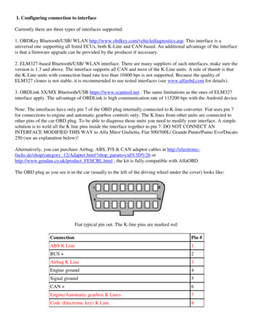
1. Configuring connection to interfaceCurrently there are three types of interfaces supported:1. OBDKey Bluetooth/USB/ WLAN http://www.obdkey.com/vehiclediagnostics.asp. This interface is auniversal one supporting all listed ECUs, both K-Line and CAN-based. An additional advantage of the interfaceis that a firmware upgrade can be provided by the producer if necessary.2. ELM327-based Bluetooth/USB/ WLAN interface. There are many suppliers of such interfaces, make sure theversion is 1.3 and above. The interface supports all CAN and most of the K-Line units. A rule of thumb is thatthe K-Line units with connection baud rate less than 10400 bps is not supported. Because the quality ofELM327 clones is not stable, it is recommended to use tested interfaces (see www.alfaobd.com for details).3. OBDLink SX/MX Bluetooth/USB https://www.scantool.net . The same limitations as the ones of ELM327interface apply. The advantage of OBDLink is high communication rate of 115200 bps with the Android device.Note: The interfaces have only pin 7 of the OBD plug internally connected to K-line converter. Fiat uses pin 7for connections to engine and automatic gearbox controls only. The K lines from other units are connected toother pins of the car OBD plug. To be able to diagnose those units you need to modify your interface. A simplesolution is to weld all the K line pins inside the interface together to pin 7. DO NOT CONNECT ANINTERFACE MODIFIED THIS WAY to Alfa Mito/ Giulietta, Fiat 500/500L/ Grande Punto/Punto Evo/Ducato250 (see an explanation below)!Alternatively, you can purchase Airbag, ABS, P/S & CAN adaptor cables at http://electronicfuchs.de/shop/category 12/Adapter.html?shop param cid%3D%26 orhttp://www.gendan.co.uk/product FESCBL.html , the kit is fully compatible with AlfaOBD.The OBD plug as you see it in the car (usually to the left of the driving wheel under the cover) looks like:Fiat typical pin out. The K-line pins are marked red:ConnectionPin #ABS K Line1BUS 2Airbag K Line3Engine ground4Signal ground5CAN 6Engine/Automatic gearbox K Lines7Code (Electronic key) K Line8
Dashboard/Climate Control K Lines9BUS -10Alarm Central Locking K Lines11K Lines engine compartment (Cruise ECU, Xenon headlamp ECU)12K Lines rear (Parking ECU, Tire pressure control ECU)13CAN -14L line15Battery 12V16Older cars (approximately before 2002) use K-line diagnostic only. A mix of K-line and CAN diagnostic is usedon newer cars like Alfa 159, Stilo, Delta, etc.The newer cars have only CAN bus diagnostic (with the exception of Mito having also a K-line for xenonlights). The high-speed CAN bus or C-CAN is connected to pins 6 and 14 of the OBD plug and the low-speedCAN bus or B-CAN is connected to the pins 1 and 9 of the car OBD plug. This setup is implemented on PuntoEVO, Punto 2012, Grande Punto, Doblo (263), Fiorino (225), Fiat 500/500L/500X, Alfa Mito, Alfa Giulietta,Ducato (255):ConnectionPin #B-CAN 123Engine ground4Signal ground5C-CAN 678B-CAN -91011K Line engine compartment (Xenon headlamp ECU)1213C-CAN -1415Battery 12V16There is one more pin out used in cars based on the new FGA CUSW architecture (examples: Fiat Viaggio,Dodge Dart), which uses different pins for the middle-speed CAN bus. The same pin out is used in Freemontand Thema (Chrysler 300):
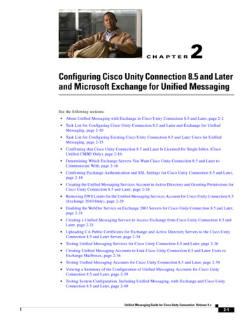
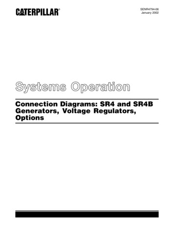
ConnectionPin #12CAN Middle speed 3Engine ground4Signal ground5CAN High speed 678910CAN Middle speed -111213CAN High speed -1415Battery 12V16By default OBDKey and ELM327 interfaces have pins 6 and 14 connected to CAN lines so they should workwith most of CAN units “out of the box”. But if you have a car with the B-CAN lines connected to pins 1 and9 or 3 and 11 you will have to modify your interface correspondingly. Alternatively, get a “Yellow” (for pins 1and 9) or “Blue” (for pins 3 and 11) adapter from http://electronicfuchs.de/shop/category 12/Adapter.html?shop param cid%3D%26 (both yellow and blue adapters) orhttp://www.gendan.co.uk/product FESCBL.html (yellow adapter only)If you do not want to make any changes to the interface itself, here is a drawing of a universal adapter cable.You will need a male and a female OBD plugs, a cable and an 8-position DIP switch. Note: this design does notinclude Viaggio, Dart, Freemont, Thema.
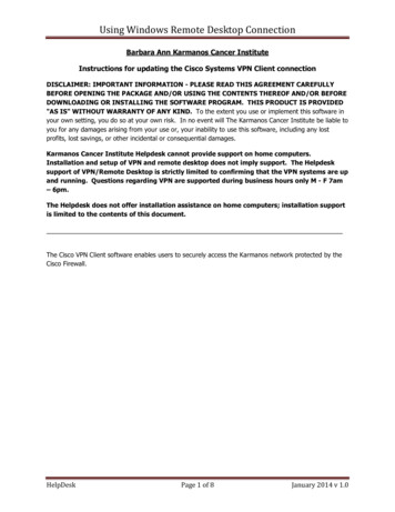
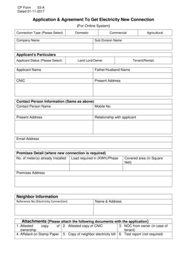
DIP switch positions:K-Lines on pins1&9 (exceptairbag)Airbag onK-Line pin 3CAN on pins6&14CAN on pins ote: The switches 1, 2 and 5, 6 can be ON together, but 3 and 4 MUST be OFF!If 3 and 4 are ON, all other switches MUST be OFF!Switch 7 controls connection of airbag unit to the interface K line, it is recommended to set switches1, 2, 3, 4, 8 OFF when 7 is ON. Switches 5 and 6 can be ON or OFF.-Using Bluetooth connectionPushbutton to open configuration screen, if BT is disabled answer “Yes” to the request to enable BT:
If you did not configure the BT interface beforehand, push “Scan for devices” button and wait until scanning is complete.You should see the interface in the list of discovered devices.
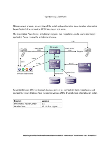
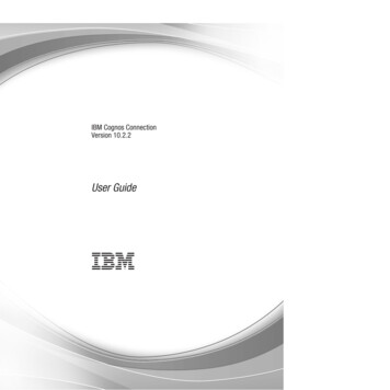
Complete pairing with the interface and select it in the list, AlfaOBD will return to the first screen and automatically setconnection to the selected interface.- Using WLANAt present Android OS does not support ad-hoc WiFi network connections. This means your Android device out of thebox will not “see” the WLAN interface’s WiFi node. To be able to use a WLAN interface you need to: Get root access to your Android device Enable ad-hoc WiFi network connectionIt is not possible to provide a universal guidance for these two steps because of differences in Android OS versions andAndroid-based devices. Search Google for guidance for your particular model.After successfully configuring connection to the WiFi interface node you need to set a static IP address for the configuredWiFi network on the Android device. The IP address has to be different from the IP address used by the interface, but ithas to belong to the same network. For example if the interface IP address is 192.168.1.10 with subnet mask of255.255.255.0, you can set IP address for the configured WiFi connection as 192.168.1.11 with the subnet 255.255.255.0.See WLAN interface manual for details on IP address and port number used by the interface.There are freely available utilities for enabling ad-hoc connections and configuring IP address of the connection. Here onthe screenshots Wifi327 is the configured ad-hoc connection to WLAN interface:
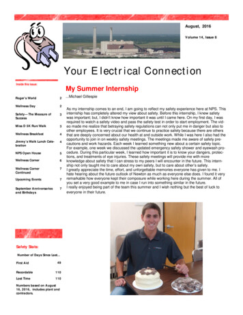
After the connection is successfully configured open Menu - Preferences and select a corresponding WLAN interfaceand enter its IP address and port number:
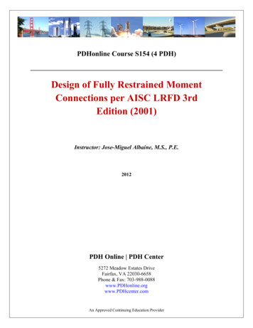
To connect to the interface start WLAN connection from the first screen. Pushconnection:button and select configured WiFiIf WiFi is not enabled it will be automatically switched on. When selecting a network in the “Select configured networks”list, wait until the connection to the network is fully established. That means, for example, that even if the connectednetwork status is “Connected”, wait until the WiFi icon in the top bar becomes white. Push “back” to return to the firstscreen, AlfaOBD will automatically try to connect to the WLAN interface on the selected network using configured IPaddress and port. If connection is successful, it is reflected in the interface status:
2. Using AlfaOBD- Configuring PreferencesPushto open the screen.The OBD interface used is selected in the "Interface" list. AlfaOBD verifies the type of the interface connected duringconnection to a car ECU. If a wrong interface selected in the preferences, AlfaOBD can correct the selection."Control Unit Timeout" determines for how long AlfaOBD waits for a ECU response after sending request before timingout the connection.“Interface Timeout” determines for how long the interface waits for additional data after receiving a part of it. In general,you should keep this parameter as low as possible to speed up communication. For the most of the ECUs the default 100ms is OK. If after the connection has been established there is a message that it is impossible to verify the connected unit,try to increase/decrease this parameter and reconnect. Sometimes adjusting the parameter helps to improve connectionstability."Request Interbyte" is the time between bytes in a request. The parameter is relevant for OBDKey interface only, and it isnot applicable for ABS5.3 and Bosch ME3.7.1, M1.7/2.7, MA 1.7 control units. The default setting should be OK in mostcases, but if the connection is unstable try to adjust this parameter."Inter Request time" is logically connected with the "Response-Request time". The communication between AlfaOBDand ECU is serial, that means it proceeds by series of request - response cycles. After sending a request for data or action,AlfaOBD waits for a response from the ECU. Only after receiving the response within the timeout limit, AlfaOBD cansend the next request. Even if no requests for data or action is made by AlfaOBD, still it has to keep sending "Testerpresent" (or "Keep alive") requests, otherwise the connection will be terminated by the ECU. Typical time of completerequest-response cycle is about 200 ms. So the "Response-Request" parameter determines time between the end of ECUresponse and the next request ("keep alive" or a request for data). Normally you can set this parameter to zero, but
sometimes to improve stability of communication it is recommended to increase the value. "Inter Request time" is thetime between consecutive requests, it varies from 200 ms to 60 sec. A longer period might be of use when scanning forslow changing data, like engine coolant or passenger compartment temperature. If high Inter Request time is selected,AlfaOBD automatically sends "keep alive" messages to ECU between the requests for data to prevent communicationbreakdown. If total "Response-Request time" value and request-response cycle time are higher than "Inter Request" valueselected, AlfaOBD built-in algorithm optimizes communication timing considering also the timeout defined in the dataexchange protocol specifications."KW71-Interbyte" is only applicable for ABS5.3 and Bosch ME3.7.1, M1.7/2.7, MA 1.7 ECUs. The parameter is relevantfor OBDKey interface only. The data exchange is different from the one described above, the communication proceedsbyte-by-byte. The parameter defines the time between the moment AlfaOBD receives a byte from ECU and the moment itsends a byte to ECU. The default setting is usually fine, try to adjust it if connection is unstable.To save the faults and system status data, check the "Log recording" checkbox. AlfaOBD will save all the data obtained ina text file which can be found in the s folder. The name of the file is ECU name Info.log, the file can be opened with a text editor.Note: Only the data received after the "Log recording" checkbox has been checked is saved.To keep the scanned data between the sessions activate “Keep session data” checkbox (see below for more information).To store the scanned data in a csv-file check “Gauges data recording”. The file is stored ogs/Gauges Data.log. The data is stored in the file in the form: eachline correspond to one measurement cycle, a line consists of time of the first measurement in the cycle and values of eachmeasurement in the cycle. The data is appended to the file each time you are scanning gauges, so the file can consist ofmany "chapters" and it will grow large over time. To manage the gauge log use Tools screen (see below).“Decimal separator” and “CSV separator” parameters set the relevant symbols used in the logs as decimal and csvseparators. If the same symbol is selected for both decimal and csv separators, AlfaOBD will automatically adjust thesymbols to be different."Debug Data recording" checkbox is for support and debugging purposes only, it should be checked when AlfaOBDSoftware needs data for troubleshooting. AlfaOBD creates AlfaOBD Debug.bin file in logs folder. You are advised to send this file to AlfaOBD Software fordebugging if requested. The file contains data exchange between AlfaOBD and ECU. Normally the check box should beunchecked, because recording of the debug data creates substantial overhead.- About screen. Activating the full version (only for non-Google Play purchase).Pushto open the screen.
There are two versions of AlfaOBD available: demo and full.The limitations of the demo version are:- Application run time limit of 15 minutes. Application returns to the first screen after 15 minutes of connection to acontrol unit.- No active diagnostic procedures available- The number of scanned gauges is limited by four- The number of monitored parameters is limited by fourAll other features are operational. No time limit is imposed on the application in demo mode.Activation of the full version purchased from Google Play is automatic, just make sure your device is connected toInternet and Google Play can be connected to.If you purchased the full version from an AlfaOBD dealer you’ll need to activate it before use. Activation is devicespecific. Push "Send activation request” and adjust the address in the activation mail if necessary. After receiving of anactivation code paste it to the “Activation code” field and push “Activate”.- Connecting and running diagnosticsSelect a make, model, function, and electronic control unit (ECU) to diagnose. Pay attention to the notification of theadaptor you need to connect between the car OBD plug and the interface. The needed adaptor is displayed in theECU list. The use of the adaptor (or corresponding modification of the interface) is absolutely necessary, no connection toECU can be done without it.From the other side, do not connect any adaptor if the notified adaptor is empty for the selected ECU in the ECUlist!It is recommended to check if any adaptor is needed BEFORE establishing connection to the interface and BEFOREactually selecting ECU to diagnose (open the ECU list but do not push on the desired ECU, just check if any adaptor issuggested for it). If you need to connect an adaptor, the connection to the interface will be lost anyways because you willhave to disconnect it from the car OBD plug, thus turning the interface power off.
After connecting of an adaptor (if needed) and establishing connection to the interface, select ECU to diagnose. AlfaOBDwill switch to the connect screen.Connect screenThe name of the control unit selected for connection is displayed in the text box at the top of the screen.Make sure that the ignition key is in MAR before activating connection. There are several exceptions to the “key inMAR” rule, some units can be also connected to with the key in Stop, see on-screen guidance.Push “Connect” button to connect to the selected control unit.AlfaOBD will automatically detect the type and modification of the connected ECU. Success of the connection and thename of the connected unit are reported in the status box under the “Connect” button. It can happen that the connectedECU is different from the one selected on the first screen. AlfaOBD automatically adjusts available parameters, graphsand diagnostic lists for the actually connected unit.If connection fails, a message is displayed with the information about possible reasons of the failure.The following connection algorithm is used by AlfaOBD:- for a KWP2000-based ECU three attempts with "fast init" are done. If unsuccessful, the application switches to "Idle"mode and a failure message is displayed.- for a ISO9141 or a KW71-based ECU two attempts are done with "slow init" (OBDKey only). If unsuccessful, theapplication switches to "Idle" mode and a failure message is displayed.- for a CAN-based ECU three attempts are done. If unsuccessful, the application switches to "Idle" mode and a failuremessage is displayed.Hint: if communication cannot be established, turn the ignition key to Stop, wait 30 sec then turn key to MAR and retryconnect. Try to reset the interface by taking it out of the OBD plug and inserting it back.
If "Automatic reconnect" is active, AlfaOBD automatically tries to re-connect if communication breaks.The status of communication is reflected in the status box. When communication has been established and the connectedECU has been verified, you can proceed with reading fault codes, running active diagnostics, or scanning sensor data atthe next tabs. If AlfaOBD can not verify the connected ECU, it displays a warning message and asks whether you want tocontinue or terminate the connection, because the diagnostic can be unreliable or not relevant.AlfaOBD verifies the connected ECU by the Fiat ISO code. If the ISO code is not known to AlfaOBD, you will see thewarning. You have an option to continue diagnostic (with unpredictable result) or terminate the connection. Please use theoption to email the unknown ISO code to AlfaOBD to include the code into the next AlfaOBD database update."Login with code card" is enabled for certain units only (engine control units, Body computer, Steering lock, TEG reader,Code control, Central Lock RF receiver). You have to login with Code Card when running some active diagnostic orconfiguration procedures on these units. Login with Code Card might be of use when, for example, there is a problemwith immobilizer which prevents engine from starting. Connect to the corresponding engine control unit, enter 5-digitcode from the Code Card supplied with your car and push "Login with code card". Engine control unit does not provideany information whether login is successful or not. Just try to start your car with the ignition key, but do not turn the keyto Stop while starting the engine. If you turn key to Stop, login has to be repeated after turning the key to MAR.Units other than engine ECU mostly provide information about success of the login, it is displayed by the software in thestatus box.Note: the Steering lock unit (Alfa 159/Brera, Fiat Croma) accepts the login only when the key is in ‘Stop’.Note: if your Code Card has been lost, contact your Fiat dealer for replacement.For the Central Lock RF receiver unit you need to login with a password before running some diagnostic procedures. Thepassword is not the same as the code from the Code Card and the password is not supplied with the car. You can try toobtain the password from your Fiat dealer. The Central Lock RF receiver does not provide any information whether loginis successful or not, so AlfaOBD just displays a message about the status of the login attempt (accepted or rejected). If theentered password is incorrect, the corresponding configuration procedures will be rejected by the Central Lock RFreceiver.You can save the code and the password to enter automatically into the box. Only one code and one password can besaved. Be aware of the security risk, because the procedure of logging with code card can be used to bypass theimmobilizer.Note: Connection to the ABS5.3 control unit can be established only if the car is stationary. The ECU terminatesconnection when the car speed exceeds 20 km/h.Status screenHere you can read and monitor information reported by ECU which is more-or-less "static".Push “Read System ID” to display control unit identification data (drawing, hardware and software numbers, ISO code,programming date etc.)Push "Read system status" to get static information from the ECU, the information reported is ECU-type dependent.Check “Auto refresh” check box and push "Read system status" to auto update the data displayed. The auto-update rate iscontrolled by the slider under the “Auto refresh” box. To stop monitoring the parameters uncheck “Auto refresh”.For particular ECUs it is possible to monitor selected parameters. Check “Monitor parameters” check box, select theparameters you wish to monitor and push. To stop monitoring push
EVO, Punto 2012, Grande Punto, Doblo (263), Fiorino (225), Fiat 500/500L/500X, Alfa Mito, Alfa Giulietta, Ducato (255): Connection Pin # B-CAN 1 2 3 Engine ground 4 . here is a drawing of a universal adapter cable. You will need a male and a female OBD plugs, a cable