Transcription
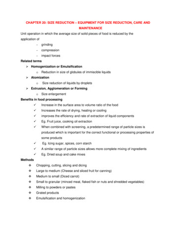
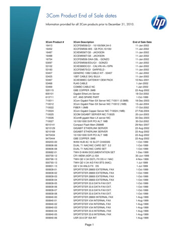
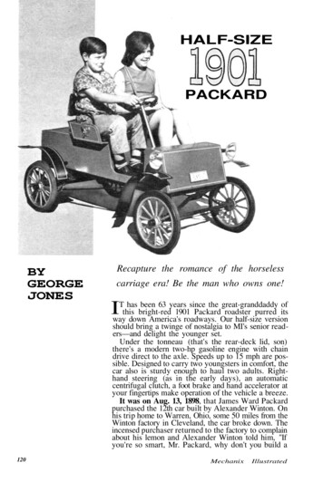
HALF-SIZEPACKARDBYGEORGEJONESRecapture the romance of the horselesscarriage era! Be the man who owns one!been 63 years since the great-granddaddy ofIwayTthishasdownbright-red1901 Packard roadster purred itsAmerica's roadways. Our half-size versionshould bring a twinge of nostalgia to MI's senior readers—and delight the younger set.Under the tonneau (that's the rear-deck lid, son)there's a modern two-hp gasoline engine with chaindrive direct to the axle. Speeds up to 15 mph are possible. Designed to carry two youngsters in comfort, thecar also is sturdy enough to haul two adults. Righthand steering (as in the early days), an automaticcentrifugal clutch, a foot brake and hand accelerator atyour fingertips make operation of the vehicle a breeze.It was on Aug. 13, 1898, that James Ward Packardpurchased the 12th car built by Alexander Winton. Onhis trip home to Warren, Ohio, some 50 miles from theWinton factory in Cleveland, the car broke down. Theincensed purchaser returned to the factory to complainabout his lemon and Alexander Winton told him, "Ifyou're so smart, Mr. Packard, why don't you build a120MechanixIllustrated
121
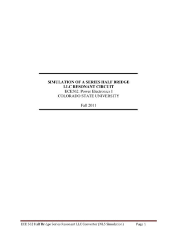
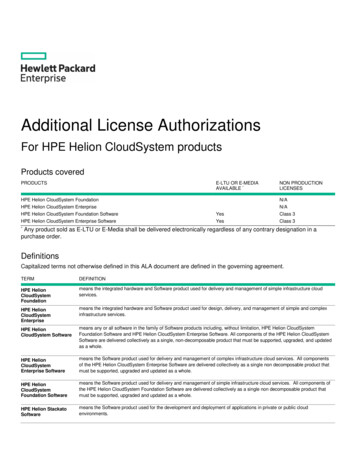
HALF-SIZEPACKARDFRAME is cut from angle iron and weldedtogether upside down. Front and rear axleand spring assemblies are bolted in place.COMPLETED chassis and running gear withthe brake pedal, brake rod, pedal-returnspring, engine and drive assembly in place.RIGHT front wheel detail shows steeringassembly—shaft, pitman arm, perch weldedto axle, drag link, tie rod and ball joints.122car yourself?" History has recorded theresults.The first Packard was sold in January1900. Almost immediately the reputation of Packard was secure. "Ask theman who owns one" became a household phrase.We hope the building of this replica1901 Packard roadster will recapturefor you some of the romance and excitement of the horseless-carriage era.The body is made of plywood, theframe of angle iron, with a minimum ofwelding. You can purchase such hardto-make parts as wheels (aluminumcast—16x1.75 with semi-pneumatictires) and hub caps, steering wheel,pillow blocks (one-inch Fafnir), balljoints and brake (Mercury strap). Theother parts, for the running gear, require but a small amount of machining.Most of the construction can be accomplished in the home workshop.[For a price list of parts and information as to where they are available, senda stamped, self-addressed envelope toGeorge E. Jones, Box 1243, MagnoliaPark Station, Burbank, Calif.']Construction begins with the frame.Have your steel supplier cut the two siderails and three cross members to lengthfrom 1/8x1.5x1.5"angle iron.If youhave a home welding outfit, you can, ofcourse, do all the welding yourself.Otherwise, have a welding shop do thejob for you. Lay the side rails upsidedown on a flat concrete surface or welding bench and butt the cross membersagainst them. With all corners square,tack-weld the joints and check the lineup, then finish the welding.Make the front axle and appendagesnext. The yokes for the spindles aremade from flat, hot-rolled steel. Cutthem to length and bend to shape in ametal vise. Drill the half-inch king-boltholes in the yoke ends. Weld the yokesto the axle tubing, centering the yokeson the axle ends and parallel to eachother. Weld the perch detail 3/16 x1-1/2 x 2-1/2" h.r.s.) to the axle.In making the spindle assemblies, notethat the right-hand spindle arm has two5/16" holes drilled in it and the left onlyone. Weld the wheel spindles (5/8x2-1/2in. cap screws ) to the spindle bodies atMechanix Illustrated
October, 1964123
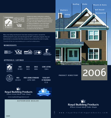
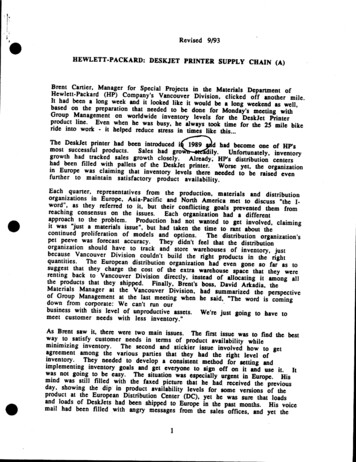
HALF-SIZEPACKARDright angles to the spindle arms.Cut and thread the drag link, tie rod,brake rod and brake support. Weld thepitman arm to the steering shaft. Insertthe studs in each end of the steeringshaft and lock them in place with rollpins. Bolt the ball joints to the spindlearms and assemble the spindles to theyokes with 1/2 x 4" hex-head bolts andlock nuts.Bend the parts for the spring assemblies in a metal vise. This work can befacilitated by clamping a steel bar or a2x4 to the end of each piece for moreleverage. Drill the necessary mountingholes in the front spring assembly andbolt the two front spring sections together with 3/8" bolts. The rear springsare made in two pieces and welded together at the ends. Drill mounting holesin the top sections where the springs willmount to the frame. Drill two more holesin the bottom halves of the springs formounting the pillow blocks later.Drill mounting holes in the frame andattach the front and rear springs. Mountthe front axle to the front spring withone-inch U bolts and shackles. Thesecan be purchased at most hardwarestores. Make sure the spindle arms arelined up parallel to the frame before youtighten the U bolts. Install the tie rodand one end of the drag link.Cut the rear axle from one-inch steeltubing and pin the 5/8" threaded stubaxles in the ends of the tube with 1/4"roll pins. Weld the drive plate to theright-hand end of the axle to drive theright rear wheel.Now would be a good time to paint therunning gear—a flat black finish. Paintthe wheels at this time, too—either goldor bronze.Assemble the brake adapter and slipit onto the rear axle. Slip a 36-toothsprocket onto the axle; also the two oneinch Fafnir pillow blocks. Mount therear springs to the pillow blocks andlock them in place.124BODY for half-size 1901 Packard is madefrom half-inch plywood, glued and screwedat all joints and then clamped overnight.SEATS are plywood upholstered with oneinch foam-rubber covered with black Naugahyde and trimmed with half-inch edging.1901 PLATE, taillights and headlights areoptional with builder. Note steering-shaftsupport, which is mounted to the dashboard.STRIPING of the body and fenders can bedone neatly by masking off 1/8" stripeswith tape and then brushing in white enamel.MechanixIllustrated
Mount the front wheels, cinchingthem on the spindles with lock nuts.Back the nuts off one-quarter turn fromthe snug position so the wheels revolvefreely. Adjust the ball joints on the tierod to give about 1/16" toe-in to thefront wheels. The left rear wheel, whichis the free wheel, is put on next. Theright rear wheel is the drive wheel andwill require two 1/4x20 tapped holes init to correspond to the hole pattern inthe drive plate. Bolt the wheel to thedrive plate. Snug the wheel with a jamnut as described. Tap on the hub caps.The engine mounting plate is madefrom 1/8". hot-rolled steel. Make thecutouts and elongated bolt holes anddrill the corner hanger holes. The fourhangers can be formed in a vise and thenbolted to the frame and the plate.The jack shaft is a length of 5/8"diameter cold-rolled steel keyed for a3/16" square key. Mount the pillowblocks (these can be purchased fromSears, Roebuck) onto the engine mounting plate, then insert the jack shaftthrough the bores and install thesprocket on the end of the shaft. Mountthe clutch on the engine shaft and position the engine (two-hp, four-cycle)on the mounting plate but don't tightenthe bolts yet. Fit the drive chains sothere is about half an inch of slack, thentighten the engine-mounting bolts andthe pillow-block bolts.Mount the brake support on the underside of the right rear spring and secure it through the eye of the brakestrap. Next, mount the brake rod itselfto the strap of the brake. The other endof the brake rod will be hooked to thebrake pedal after the body has been installed.The fenders can be molded from fiberglass or rolled from 22-gauge coldrolled steel. The eight fender bracketsare bent in a metal vise. Paint thefenders glossy black. Mask them withtape and stripe them with white enamelpaint.Cut all panels for the body from halfinch plywood. All joints are held fast bywood screws and waterproof glue. Cutthe foot-pedal slot and drill the steeringshaft clearance hole in the floorboard.Attach the [Continued on page 143]October,1964MI PLANS SERVICEMore than 140 tested plans {or boats,furniture, models, photo equipment,telescopes and other projects are offeredby the MI Plans Service. For a copy ofPlans Catalog No. 15, send a dime toMI Plans Service, Fawcett Bldg., Greenwich, Conn. 06830. The Half-Size 1901Packard plans are offered by the PlansService at 3 per set as Plan No. 10-64.125
Half-Size 1901 Packard[Continued from page 125]seat top and hinge the tonneau lid to itwith brass hinges. Add trunk-type latchesto secure the lid when shut.Upholster the seat and backrest withone-inch foam rubber and cover with blackNaugahyde. The seat cushion is removable,but the backrest is attached permanentlyby the two back braces and the arm rests.Paint the back braces and the arm restswith glossy black enamel and set them[Continued on page 144]I
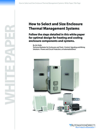
Half-Size 1901 Packard[Continued from page 143]aside to be attached after the body ispainted.Go over the entire body, filling thecountersunk screw holes with plasticwood. Sand all surfaces smooth and coatwith a filler. Then paint the body with anundercoat and finally with bright redenamel—two coats, sanding and dustingbetween coats.Attach the body to the frame withquarter-inch carriage bolts. Insert the footpedal through the slot in the floorboardand mount it to the brake spacer attachedto the frame. Attach a return spring to thepedal and the other end of the frame crossmember. Attach the brake clevis to thebrake rod and then to the brake pedal, adjusting the tension to get a positive returnaction. Next, attach the tube-and-wirethrottle control (purchased from your engine dealer), attaching the wire to thecarburetor, according to the instructionspacked with each engine. The other end isattached to the throttle-control handle(similar to lawn-mower control handles)mounted on the seat side near the driver.Secure the conduit to the underside of thebody with conduit clips.Bend the steering shaft support to shapeand drill the one-inch clearance hole. Paintthe piece, let it dry, then mount it to thedashboard panel. The steering shaft, whichis painted gold, is slipped from the underside of the floorboard through the clearance hole and secured to the perch with alock nut, allowing the shaft to turn freely.Attach the free end of the drag link to thepitman arm. Install the steering wheel andsecure it with a half-inch acorn nut. Drillthrough the slot in the cast aluminumsteering wheel to allow for insertion of aroll pin to secure it to the steering shaftand prevent it from slipping.Attach the fender brackets and thefenders, allowing about a four-inch clearance above the wheels. Headlamps andother accessories may be attached as youdesire.de-clutch when you release the handthrottle. And away you go!You and the kids will have years of enjoyment with your 1901 Packard. Be theman who owns one! Now for the official trial run of your1901 Packard. Make sure all nuts and boltsare tight. Fill the engine crankcase to theproper oil level, gas up and start the engine. Adjust for idling speed so it will144October, 1964
drive direct to the axle. Speeds up to 15 mph are pos-sible. Designed to carry two youngsters in comfort, the car also is sturdy enough to haul two adults. Right-hand steering (as in the early days), an automatic centrifugal clutch, a foot brake and hand acceler