Transcription
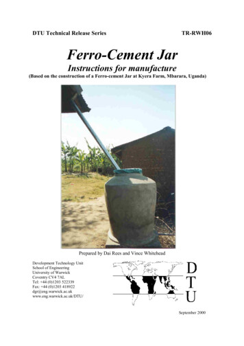
DTU Technical Release SeriesTR-RWH06Ferro-Cement JarInstructions for manufacture(Based on the construction of a Ferro-cement Jar at Kyera Farm, Mbarara, Uganda)Prepared by Dai Rees and Vince WhiteheadDevelopment Technology UnitSchool of EngineeringUniversity of WarwickCoventry CV4 7ALTel: 44 (0)1203 522339Fax: 44 (0)1203 TU/September 2000
2Contents:1.Introduction . 42.Merits and drawbacks of the Ferro-cement Jar . 43.Ferro-cement Jar specifications . 45.Tools and equipment required . 56.Jar Costing . 67.Site selection . 68.Manufacturing procedure for the jar . 79.Care of the jar on completion. 11Appendix 1: Low cost threading of PVC pipes using a standard galvanised iron (GI)pipe fitting . 12
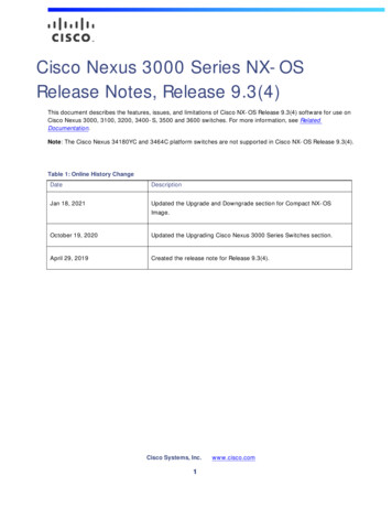
t andTapPlinthCutaway drawing of a ferrocement tank
41. IntroductionThis manual gives guidelines for the manufacture of a 500 litre Ferro-cement Jar, whichwas based on a jar built at Kyera Farm, Mbarara, Uganda during June and July 2000.The jar basically consists of a brick plinth, a Ferro-cement shell, and a filter basin.This is a well proven technology that has been successful in Thailand, these weretraditionally made from a rendered bamboo mould but now they use chicken mesh, 10million jars were built in Thailand between 1985 and 1992.2. Merits and drawbacks of the Ferro-cement JarPros: Has the potential for small/large scale production by artisans.Very low maintenance.Repairs can be easily carried out.Low cost.Suitable for most ground conditions.Good protection against mosquitoes.Cons: The level of skill required is quite high (based on recent experience in Kyenjojo,Uganda)3. Ferro-cement Jar specificationsTable 1 gives the specifications for the jars main features:Table 1 Ferro-cement Jar specificationJar external diameter0.84m (approx. at the widest point.)Jar internal diameter0.80m (approx. at the widest point)Jar height1.25m (approx.)Jar capacityApproximately 500 litresJar lining (inner surface) Waterproof renderWall thickness20mmWall compositionChicken mesh sandwiched between inner and outer coatof renderWater extractionGravity via tapPlinthBrickwork 0.8 x 0.8 x 0.5mTopPVC filter basinN.B. See page 11 for Jar and plinth dimensions
54.Material and labour requirementsTable 2 Material and labour requirements for the jar.Units RingbeamCement (OPC) kg10Sandkg20Aggregatekg40 50mmBricksno(household size)RubblekgChicken mesh m0.5" x 0.9m rollwidthGI Pipe 1"mGI Elbow 1"noPVC Pipe 1.25" mTap 0.5"noReducer 1" no0.5"BasinnoLabour (skilled) daysLabourdays(unskilled)5. BaseInfill12.5756301st coat 2nd coat20602060Water Totalsextraction68.524540100Tools and equipment requiredSpade or shovelHoeSpirit level (600mm)BucketTrowelsPlasterers floatTape measure (3m)Tin snips or wire cutters (for mesh)Pipe wrench10075753.23.20.510.5110.510.5111124
66.Jar CostingTable 3 gives a breakdown of the materials used for the jar and their costsTable 3 Jar costingItemUnitCementkgSandkgAggregatekg 50mmBricksnoRubblekgChicken mesh m0.5"GI Pipe 1"mGI Elbow 1" noPVC Pipem1.25"Tap 0.5"noReducer 1" - ed)No reqd68.524540Unit 40.06Material costsTotal cost (incl. labour)Cost per litre stoargeCost per litre storage (incl.labour)Total (UGS) Total (US ) Total ( )2055013.709.2649003.272.2110000.670.45Notes Mould cost not included - cost of mould is approx. 6000UGS (US 3.38) and may lastfor up to 10 or 15 jars depending on care taken during manufacture Larger sizes of jar - say up to 1500 litres - can be achieved by experimenting with themould sizeSawdust can be obtained from local sawmillsThe volume is obtained by using a bucket of known volume and counting theappropriate number of buckets of sawdustSome transport costs included (i.e. for sand, aggregates and bricks)Cost of bucket slab not included7.Site selectionIt is important to select the right site for the jar so that it will remain a reliable source ofwater for years to come.
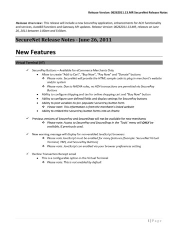
7Some pointers for what constitutes a good site are given below: Good ground stability (i.e. not sandy soils). Jar should be close enough to the dwelling to avoid long lengths of guttering anddownpipe (some suggest siting the jar mid way along the length of a building toreduce gutter size– this is fine if water from one side of the building only will be fedinto the jar). Reasonably flat where possible – otherwise the ground will have to be levelledbefore marking out. Away from trees which may undermine the foundations and cause cracking. Away from areas where animals will wander – fence off if needed. Not so close to the dwelling that the foundations are undermined. Somewhere convenient for extracting water e.g. close to the kitchen area. It must be a suitable distance away from vehicle access as this may cause groundmovement, fence off if necessary.8. Manufacturing procedure for the jarPrepare a level piece of ground approximately 1.0m square.Mark out an inner and outer square with sides of 0.85m and 0.0.55m respectively asshown in Figure 1.0.85m0.55mFigure 1 Inner and outer squares for the plinth foundations Carefully excavate between the two squares to a depth of 10cm. (NB if soil tends tobe unstable excavate to 20 cm deep and fill with aggregate 10cm deep, alternativelymake a larger deeper ring beam)Fill the excavation with a concrete mix of 4:2:1 (aggregate: sand: cement) and coverwith damp grass/leaves and leave for two days.Start building the brickwork, with aplinth outer size of approximately 0.8m, on top of the concrete ring using a mortarmix of 5:1 (sand: cement) to a height of 0.55m as shown in Figure 1. Leave a gap inthe top course of bricks for the outlet pipe.Fill the centre of the plinth with rubble/aggregate, compacting it well to prevent latersettling.
8Figure 1 Brickwork plinth Cut off a length of 3/4” GI pipe and fit on a 3/4” elbow at one end and a 3/4”to 1/2” reducer and a 1/2”tap at the other. Local plumbers can thread the GIpipes, alternatively a low cost method of threading 3/4” PVC pipe is explained inAppendix 1.Cut off a piece of pipe 25mm long pipe that has been threaded at one end and fit thisto the elbow. This will give the jar a settling zone, but it can also be removed forwashouts.Dig out a channel in the rubble and place the pipe in so that the tap and the elbow arevertical. N.B. make sure the top of the elbow is 3cm above the level of the rubble.Apply a 1cm layer of mortar to the top of the rubble and flush with the edges of theplinth, apply a layer of damp material and cover with plastic sheet, leave this to cure.Prepare a disc of mortar 0.6m diameter by 1cm deep on to the plinth base.Cut out a ring of chicken mesh to a diameter of 0.75m and turn up the edges 0.1m, sothat it leaves a base diameter for the jar of 0.55m.While the disc of mortar is still damp lay the chicken mesh on to the top of this andthen apply another layer 1cm deep to the mesh this should be level with the top ofthe elbow.
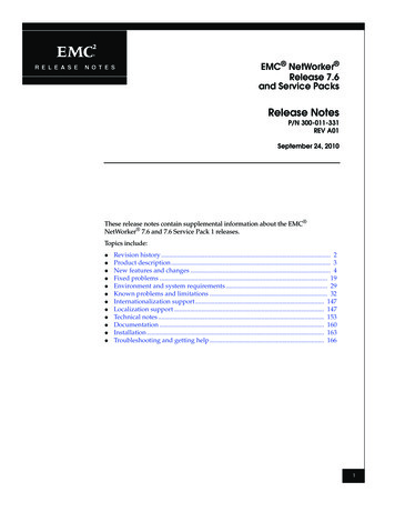
9 Cut out and sew up a polypropylene or hessian sack to the dimensions shown inAppendix 2.Figure 2 The filled polypropylene sack mould Fill the sack mould with sawdust (rice husk, coffee husks, sand or any other similaravailable material) and compact it as it is being filled. When full tie it up at the topand pat the sides to produce an even symmetrical shape then place this on theprepared base of Ferro-cement as shown in Figure 2. The capacity of the jar can bedetermined by filling the sack with buckets of known volume, simply count thenumber of buckets to until 500 litres is achieved.Place a medium sized basin centrally on top of the mould with a short length of PVCpipe for the overflow. Apply the first coat of mortar of 3:1 mix with a waterproofadditive (quantity as per manufacturers instructions) to a thickness of 1cm as shownif Figure 3, (the thickness may vary as the irregularities of the mould shape iscompensated for)
10Figure 3 Overflow, filter basin and first coat application When the first coat has been applied cover with a damp cloth and a plastic sheet,leave for 24 hours, making sure the cloth is kept damp.Wrap around the jar a suitable length of chicken mesh to cover the whole area up tothe filter basin pull the mesh tight and fix with short lengths of wire to secure inplace as shown in Figure 4.Apply the second coat of mortar (make this layer smooth by rubbing over with asmall wooden hand float) also apply mortar around the tap outlet to secure it to thebase and jar side as shown in Figure 5.Figure 4 Applying the mesh ontop of first coat
11 Cover the shell again with a damp cloth and a plastic sheet, leave for 48 hours.When the shell is firm carefully remove the filter basin and untie the mould bag, andcarefully take out the contents.Fill the bottom of the jar with enough water to come up to the level of the outlet pipeand replace the damp cloth with the plastic sheet and leave for 7 days to cure.Make a series of about twenty holes in the bottom of the basin using a hot nail or adrill (Ø6mm) for the rain to enter the jar. Fill the basin with aggregate (about 20mm)to about one third full.Cut out a section of clean cloth that will cover the basin and have sufficient tooverhang down the sides, then tie around the sides of the basin with string or rubberinner tube strip to hold the cloth in place.Figure 5 Detail of the outlet fixing 9.Lower the basin on to the top of the jar.Fix the appropriate gutter to the roof and place the downpipe directly on to the cloth.Cut out a small piece of mosquito mesh and fit this on to the end of the overflowpipe with string/twine etc.Care of the jar on completionOnce the jar is finished and has cured for 7 days, fill with 125mm (5”) of water each dayso that the structure is gradually loaded rather than all at once.It may be noticed that the jar will leak slightly somewhere around the sides, it is best if thisis left for at least a week, as quite often the jar will eventually seal itself if the hole is small(based on masons personal experience in Uganda). However, if it shows no sign of sealingor the hole is quite visible, empty the jar and make the repair with a nil mix (i.e. purely acement and water mix) from the inside of the jar.It is important that there are no gaps around the filter and cover, or around the filter wherelight can enter as this will not only encourage the growth of algae but may be an entrypoint for mosquitoes both of which should be avoided. The water may have a cement tasteat first so either rinse out well several times or use the jar for washing rather than cookingfor the first few times.
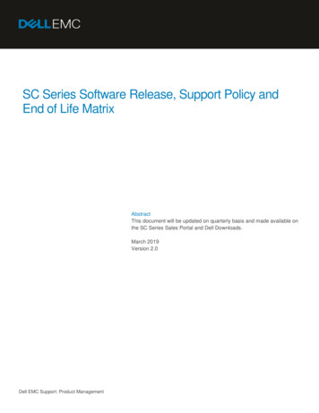
12Appendix 1: Low cost threading of PVC pipes using a standard galvanised iron (GI)pipe fittingThere are many occasions were threads are required on PVC pipes so that other fittingscan added to the pipe. This often involves the use of expensive threading equipment,which is not always available when needed and the charge for this service can becomeexpensive when it is done repeatedly.The method described here was tried out in Uganda after finding the problems mentionedabove and was found to be a useful and successful solution that was very low cost. Thoughit requires some tools, a little bit of skill and some patience, once it has been made it willlast for many threading operations and re-sharpening is simple to do.The following example is for a ½” PVC pipe but the same procedure is carried out forother sizes:Tools required:One hacksaw blade (preferably with 24 teeth per inch)A small (6”long) triangular file (the width across the faces should preferably be no morethan about 3/16”or 4mm)Pipe grips or a vice.10” rough flat file.The reliability of the threads for higher pressure applications has not been checked andcare will be needed when trying this out.End threadsCentralthread1. Take a normal GI ½” Tee fitting as shown in Figure 1 and make three equally spacedsaw cuts with the hacksaw blade in the central part of the Tee to just beyond the rootsof the thread as shown in Figure 2.
13End threadsCentral threadThread rootDetail of saw cuts inthreadFigure 2 The GI Tee with the saw cuts equally spaced round the central thread2. Make additional saw cuts as close as is practically possible to the first thread so that itis slightly wider than one of the faces of the triangular file, this is to ease the burden offiling.3. Proceed to file each of the saw cuts so that the roots of the thread can no longer beseen.4. File the left-hand side of the slot, as this will be the cutting edge, so that the profile isthe same angle as the file i.e. 60 as shown in Figure 3.Small triangular file is usedto produce the cutting edgeprofileFigure 3 The GI Tee with detail of the cutting edge profile on thread5. Using a rough file chamfer the end of the pipe to be threaded to the dimensions shownin Figure 4.
Ferro-Cement Jar Instructions for manufacture (Based on the construction of a Ferro-cement Jar at Kyera Farm, Mbarara, Uganda) . Fill the excavation with a concrete mix of 4:2:1 (aggregate: sand: cement) and cover with damp grass/leaves and leave for two days.Start building the brickwork, with a plinth outer size of approximately 0.8m, on top of the concrete ring using a mortar mix of 5 .