Transcription
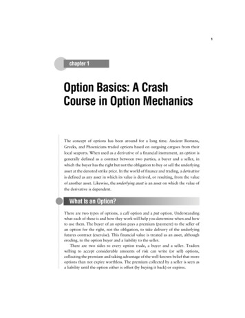
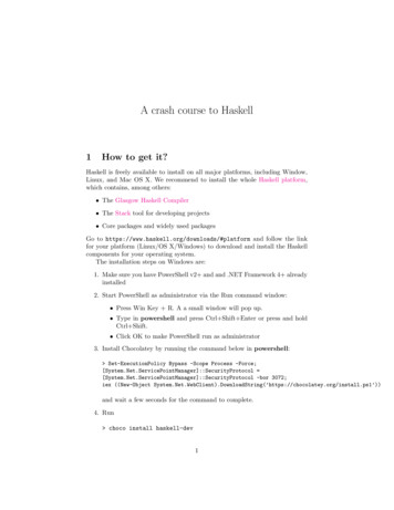
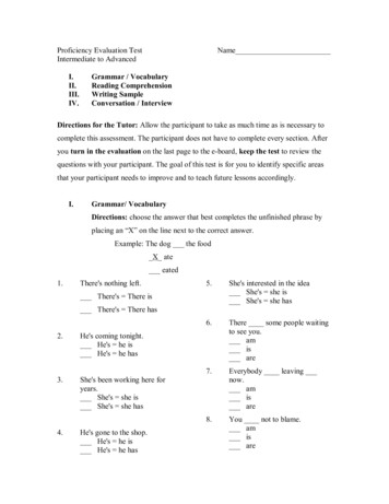
TRANSPORTATION RESEARCH RECORD 1133Crash Test Evaluation of the VehicleAttenuating Terminal (V-A-T)E. BRONSTAD, K. L.P. HUMBLEMAURICEWALTERHANCOCK, LEONARDAn energy-absorbiug guardra il tem1lnal (end treatment) wasdesigned and partially developed in a Federa l Highway Ad·mini tration contract at Southwest Research Institute (SwRJ).The development of this device was completed by Syro SteelCompany under contract to SwRI. The vehicle-attenuatingtermina l (V·A·T) described in this pa1ler is a unique eoergyab orbing design to attenuate vehicle energy in end-on Impacts. T he basic principle of tltis design uses tlle tearing ofmetal between slots specially punched in W-beam sections toabsorb the energy. The de ign also provides essential anchorage f'or guardrail Impacts downstream of the terminal.This paper reports the results of a crash test series conductedaccording to tl1e terminal test requirements of NCRRP Report230 with 1,800-lb (820-kg) and 4,500-lb (2040-kg) test vel1icles.Results of the crash test series indicate compliance with Report230, and recommendations for V-A-T use are given.An energy-absorbing guardrail terminal was conceived andpartially developed in an F:HWA contract (1) at SouthwestResearch Institute (SwRl). Because 1he development was notcompleted in the FHWA contract, Syro Steel Company approached FHWA and SwRI about the possibility of completingthe development Wlder a Syro contract to SwRI. An agreementwas reached and Lhis reporl describes the comple1ion of thedevelopment of 1he new guardrail terminal.Before work on I.his project began, a meeting among Syro,FHWA, and SwRI personnel was held to finalize the designwith a goal of cosl reduction and simplicity. As a result of lhismeeting, several significant change-s were made in the designdetails from Lhe previously mentioned FHWA contract effort.The purpose of this project was to demonstrate the perfor·mance of the vehicle-auenuaring-terminal (V-A-T) system in aseries of crash tests. NCHRP Report 230 (2), the currentlyrecognized rccornmendated procedures for highway safety appurtenances, requires four rests to qualify a barrier tennlnal.This test program was conducted by using the procedures ofReport 230, and the resulrs are compared wilh the crileriarecommended in this report.M. E. Bronstad, Dynatech Engineering, Inc., 8023 Vantage, Suite 900,San Antonio, Tex. 78230. K. L. Hancock, Southwest Research Institute, 6220 Culebra Road, San Antonio, Tex. 78284. L. C.Meczkowski, Turner-Fairbank Highway Research Center, FederalHighway Administration, U.S. Department of Transportation, 6300Georgetown Pike, McLean, Va. 22101. W. P. Humble, Syro SteelCompany, 1170 North State Street, Girard, Ohio 44420.C.MECZKOWSKI, ANDFINDINGSThe V-A-T system (Figures l and 2) is designed 10 provideadequate anchorage for W-beam guardrail systems and Lo be acrashworthy energy-absorbing system when struck end-on byerrant vehicles. The V-A-T is a three-stage system utilizingenergy-absorbing beam elements, breakway Limber posts, and acable anchorage system.The first stage uses Oat beam elements to facilitate cableanchorage hardware, and the second and lhird st.ages use standard W- beam elements with slots installed along the splice boltlines in the conugations. Sequenlial energy absorption for endon impacts is achieved as follows.Stage 1: The vehicle readily collapses the leading nose clement and fractures Posl 1, releasing lhe anchor cable. The fiatplate elements (Span 1) continue to collapse.FIGURE 1V-A-T before test.
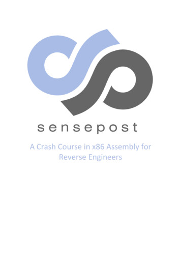
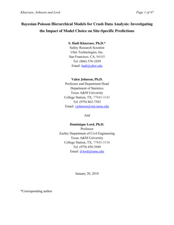
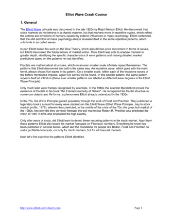
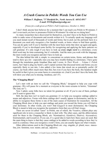
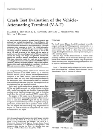
TRANSPORTATION RESEARCH RECORD 11332FIGURE 2 Design drawing, V-A-T system.Stage 2: After the first span beams have collapsed, stripsbetween the second beam (12-gauge W beam) slots are forcedthro11gh the splice bolts at a predetemiincd force level; Post 2 isfractured shortly after this stripping begins and later Post 3fractures before all the 12-gauge strips separate.Stage 3: After all the ·trips in the 12-gauge beams (Spans 2and 3) are stripped, stripping of the 10-gauge beam (Spans 4and 5) begins, and l'osrs 4 and 5 fracture as the vehiclecontinues into the system.Staging of the system is such that the 1,800-lb (820-kg) curat 60 mph (95 km/hr) is only involved in the firs t three spans;mo{e severe impacts, including the 4,500-lb (2040-kg) car at 60mph, reqnire that the third stage be acLivated. The three stagesare sequentially activated, so damage is related co the severityof the impact. A functional description of all V-A-T components is given in Table 1.CRASH TEST FINDINGSSix crash tests were conducted in this project. One of the fourterminal tests was repeated twice before satisfactory resultswere obtained. The crash test series as summarized in Table 2 isbriefly described in thi paper; detailed test reports includingthe data may be found in the final report of this project (3).Test Syro-1Test Syro-1 evaluated the V-A-T for the 60-mph end-on condition with the 4,500-lb car centered on the nose of the terminal.As shown in Figure 3, the vehicle struck the nose and wasbrought to re t in contact with the barrier after 27 ft (8.3 m) oftravel. All values measured during the test were in conformance with the recommended requirements of NCI-IRP Report230 with the exception of the 16.-g ridedown accelcraLion;however, this value is below the 20-g threshold value. Photographs taken after the tesL are shown in Figure 4.FIGURE 3Test Syro-1 sequential photographs.Test Syro-2Te L Syro-2 evaluated the anchorage strength of Lhc rcnninalwith a 4,500-lb car al 60 mph in a 25 -degrcc angle impact. Thislength-of- need for the V-A-T begins at Po t 4, which is Lhcinitial impncl point for I.his test. As shown in Figure 5, thevehicle's impact was at Post 4 and it was smooth1y redirected
TABLE lFUNCTIONAL DESCRIPTION OF V-A-T COMPONENTSComponentDescriptionFunctionNose10-ga flat beam w/curvedendProvide collapsible connectionfor anchor cable.Cableanchorage 13/4-in. cable assemblyw/hardwareAnchors traffic side beam fordownstream impacts.Cableanchorage 23/4-in. cable assemblyw/hardwareAnchors opposite traffic sidebeam for third stage reaction;not needed for median barrierV-A-T.Posts 1and 26x8 breakaway wood post/steel tubeProvide cable anchorage andbeam support. Steel tubesincrease soil resistance.StrutSteel channel w/tabsCouples steel tube foundationsat Posts 1 and 2 to react cableanchorage forces.Posts 3and 56x8 breakaway wood posts(2 holes)Provides lateral beam support;not connected to beams. Astested, used full length postsw/2 breakaway holes.SpreaderchannelSheet metal weldmentCouples the slotted W-beamsbehind Post 2 to promote uniformbeam translation for off-centerend-on impacts.Post 46x8 breakaway wood postsProvides beam support; upstreamend of span 4 beam is attachedto this member.BeamSpans2 and 312-ga slotted W-beamAbsorbs energy of vehicles impacting end-on by tearing of stripsbetween slots - second stage.BeamSpans4 and 510-ga slotted W-beamAbsorbs energy of vehicles impacting end-on; a higher force levelthan the 12-ga beam of stage 2.5/8 diaspliceboltsHex head bolt w/unthreaded shankTiiis bolt transfers tension fordownstream impacts and causestearing of strip for end-onimpacts. Unthreaded shank preventsexcessive clamping of splice joints,thus facilitating telescoping actionPlatewasherRectangular washer usedat splice boltsHolds splice together asstripping action occurs.3/8-in.dia rodsThreaded rod or bolt w/threads at both endsHolds beam sections togetherdownstream of Posts 3 and 5.Shortsteel tube6x8 box beamPlaced upstream at Posts 4and 6 to separate 3/8-in. diarods from assembly afterrequired translation has occurred.Postplate1/2-in. thick steelplatesPlaced at upper part of Post 4to prevent splitting when end-onimpacts occur. This is the onlypost that is connected to a beambetween Posts 2 and 7.
TRANSPORTATION RESEARCH RECORD 11334TABLE 2SUMMARY OF V-A-T CRASH TESTSSyro-1Syro-2Syro-4Syro-6Report 230 Test No.41404445BarrierV-A-TV-A-TV-A-TTest Vehicle1978 Dodge43401980 Honda1804V-A-T1980 HondaGross Vehicle Weight, lb1978 Dodge4400Impact Speed (film), mph59.360.060.660.6Impact Angle, deg0.524.416.00.9Impact Duration, sec0.680. 710.260.42Maximum DeflectionDynamicPermanent27 ft25 ft3.2 ft2.1 ft0.5 ft0.1 ft17.416.0Exit Angle, degFilmYaw Rate Transducerdid not exitdid not exit-17.2not avail-3. 6-2.729.328.6Exit Speed, mphFilmAccelerometerdid not exitdid not exit34.9not avail50.751.8-2. 3Maximum 50 msec Avg 0/-9.8-4.0/2 . 6Occupant Risk, NCHRPReport 230 (film/accelerometer)6V long., fps (30) v lat, fps (20)24.5/22.6 n/an/a12.9/7.918.8/21.6*30.4/27.6-7.5/-5.6Ridedown Acceleration, g's(accelerometer)Longitudinal (15)Lateral (15)-16.3 5.4n/an/a -6.6-16.9*5.7NCHRP Report 230 Evaluation(Table 6)Structural AdequacyOccupant RiskVehicle Trajectorypassed (C,D)passed (E,F*)passed (H)passed (C,D)passed (E)passed (H,I)passed (C,D)passed (E,F*)passed (H)passed (C,D)passed (E,F)passed (H,I**)Test No.1840-1.4 Numbers in parentheses are recommended values for NCHRP Rep ort 230 . occupant did not travel the flail distance. Higher than reco11111ended (Report 230, Table 8) but lower than threshold values (Re port 230,Table 6)**See Conclusions in text.n/a - not applicable.as desired. This test met the criteria of NCHRP Report 230.Photographs after the test are shown in Figure 4.Test Syro-3Test Syro-3 evaluated the V-A-T for the 1,800-lb car end-ontest at 60 mph with a 15-in. (38-cm) offset (centerline of car tocenterline of barrier). The actual offset at impact was 17.5 in.(44.5 cm) and resulting performance of the system was not asdesired because only one side of the span two-slotted beamswas acLuated in !he strip-tearing mode. The vehicle pun awayfrom the barrier after only 4 ft (1.2 m) of beam had "stripped."Analysis of the data was su ·pended pending a decision onretest in light of the extreme offset dimension.Test Syro-4Test Syro-4 evaluated the terminal for the NCHRP Report 230Lest specifying impact of an 1,800-lb car midway belween thetenninal end and the length-of-need al 60 mph and a 15-degrecangle. As shown in Figure 6, the v hicle's impact was midwaybetween Posts 2 and 3, and it was smoothly redirected. Testvalues measu red were in conformance with NCHRP Report230, as described in Table 2; phoLographs after the test areshown in Figure 4.Test Syro-5A decision to repeat the planned test conditions of Syro-3 wasmade. A similar result occurred in this test and a design
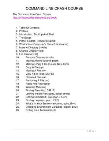
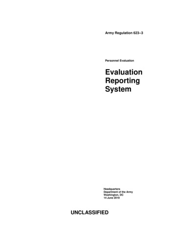
5Bronstad et al.Syro - 2Syro-6Syro-4FIGURE 4 After-test photographs, Tests Syro-1, Syro-2, Syro-4, Syro-6.FIGURE 5 Test Syro-2 sequential photographs.modification was indicated. Specifically it wa noted lhat theoff-center impact was causing a differential translation of theSpan-2 beams because of Lhe lack of vehicle contacl w.ilh lhcfar-side beam. A spreader channel as shown in Figure 1 anddescribed in Table l was desig11ed to couple the beams andpromote unifonn translation in cases where only one beam waessentiall.y in contact wilh lhe vehicle.FIGURE 6 Test Syro-4 sequential photographs.Test Syro-6The spreader channel wa installed bcfor this test; all otherdctni ls were identical Lo those used in previous tests. The1,800-lb vehicle struck the nose of the tenninal at 60.6 mph(97 .6 km/hr) and 15 in. (3 cm) offset (from centerline of nosetoward the traffic ide). As shown in Figure 7, the test vehiclestmck the nose and began yawing as the first two stages were
TRANSPORTATION RESEARCH RECORD 11336FIGURE 7Test Syro-6 sequential photographs.essentially consumed. The vehicle was brought to a stop incontact with the barrier; elaslic spring in the system pushed thecar away from the barrier when the yaw angle was 29.3 degrees. The occupant risk criteria for longitudinal and lateral Y-values were in compliance with NCHRP Report 230. Themaximum ridedown acceleration of 16 g was greater than the15-g recommended value but below the 20-g threshold value.Vehicle trajectory values did not confonn with NCHRP Report230 guidelines; this is discussed in a following section. Photographs after the test are shown in Figure 4.end-on and absorbs the energy of the vehicle in a controlledmanner.2. Trajectory values as given in NCHRP Report 230guidelines (2, Table 6) have l roved difficult to meet, particularly in off-center impacts with the 1,800-lb car. An energyabsorbing terminal or era b cushion with a reasonable .forcelevel (in order to minimize length) will cause the rear wheels oflhe minicar to lose traction, and when this is coupled with theoff-center impulse, severe yawing of the vehicle often results.This makes it difficult to mce1 Table 6 trajectory requirementsH and I when the offset is to the Lrafnc side. The perfonnanceof Test Syro-6 is considered to be as good as can be expectedwi.thmu lowering the energy-absorbing force to a level thatwould require an unreasonably long terminal or crash cushion.3. The placement of the spreader chaMel for Test Syro-6was considered an essential modification w.ith desired performance demonstrated. The addiLion of this member is not considered important to the results of previous tests, and thusretesting is not considered necessary. Regarding this matter, thefollowing observations are made:a. The spreader channel was not in the impact zone forTests Syro-2 and Syro-4; no potential effect on either of thesetests is considered to ex ist.b. The function of the spreader channel is to promote theuniform translation of two beams when only is loaded. Becausethe beams moved uniforrnJy in Syro-1, no significant change inthe barrier pcrfonnancc is envisioned with the addition of thespreader.RecommendationsOn the basis of the findings of this test series, the V-A-T systemas described in Figures 1 and 2 is recommended for immediateapplication as an experimental device.Use of steel foundation tubes at nil posts in the V-A-T lengthcould be specified at sites where frequent impacts and damagerepair are expected. Po t removal and replacement are facilitated by the use of these steel tubes.REFERENCESCONCLUSIONS AND RECOMMENDATIONSConclusions1. M. E. 13ronstad, J. B. Mayer, Jr., and L. C. Mcc-.tkowsk:i. Guardrailand Median Barrier J'erminals for Mini.Size Cars, Volume I: Research Report. Report FHWA!RD-85/062. FHWA, U.S. Depart-On the basis of the findings of this project, the followingconclusions are drawn.ment of Transporc.ation, May 1985.2. J. 0. Michie. NCNRP Report 230: Recommended Procedures for1. The V·A-T system as evaluated in this project essentiallypassed the criteria of NCHRP Report 230. Unlike other terminals that redirect vehicles with uncertain and often unstablepostimpact trajectories, the V-A-T captures vehicles strikingtire Safety Performance Evaluation of Highway !\ppurtenances.TRB, National Research Council, Washington, D.C., March 1981.3. M. E. Bronscacl and J. B. Mayer, Jr. Crash Test E11aluatio11 of tireVehicle Attenuating Terminal (V-A-1}. Final Reporr, SouLhwest Research In d. lutc Project 06-1004. Southwest Research Institute, SanAntonio, Tex., May 1986.
with a goal of cosl reduction and simplicity. As a result of lhis meeting, several significant change-s were made in the design details from Lhe previously mentioned FHWA contract effort. The purpose of this project was to demonstrate the perfor· mance of the vehicle-auenu