Transcription
MOTORVACTECHNOLOGIES INC.Service ManualTRANSTECH II-ATRANSTECH III-AMTT1100 Series(Single Solenoid)Transmission Service System200-8243i
Table of ContentsIntroduction . vOverview . 7System Features and Functions.1-1Control Panel Features and Functions1-3Left View1-4Right View 1-5Theory of Operation 1-6Safety Information.2-1Before You Begin .3-1First Time Operation3-1Transmission Service Procedure .4-1Frequently Asked Questions .5-1Troubleshooting and Additional Help.6-1Checkout Procedure6-3Calibration Procedure Internal Wiring Diagram6-5Flow Charts 6-6Component Identifier 6-10Circuit Board Replacement6-13Cleaning Filter Screen 6-13Tech Tips6-146-4Appendix B - System Accessories. B-1Adapter Kits . .B-1Appendix C - Parts . C-1External Parts C-1Ordering Parts ii200-8243C-1
Notes:200-8243iii
IntroductionCongratulations on your selection of the TRANSTECH Transmission Service System. By choosing this product,you are acquiring the most technologically advanced method available for automatic transmission service and fluidexchange.The TRANSTECH System is a self-contained system; designed to connect to any automatic transmission throughit’s cooling system lines. Once the unit is connected, it can be used to drain the fluid from the vehicle’s transmissionfor filter replacement and/or to completely exchange the transmission fluid with new fluid, without removing thevehicle’s transmission fluid pan.With the engine idling, the unit will receive the used fluid expelled by the vehicle’s transmission fluid pump throughone of the hoses connected to the transmission cooling system, and supplies new fluid through the second hoseconnected to the other side of the disconnected transmission cooling line.It is recommended that a vehicle’s transmission lubrication system be serviced every 15,000 miles(Or according to the vehicle owner’s manual) to obtain the highest lubricant protection, to reduce friction frominternal transmission components, and thus increase the efficiency and life span of the transmission to it’smaximum.Please study this Operators Manual to become thoroughly familiar with the TRANSTECH Transmission ServiceSystem.IMPORTANTThe TRANSTECH Transmission Service System is designed to workEXCLUSIVELYwith Automatic Transmission Fluid.Use of any chemical during this process may cause operational failure of theTRANSTECH System and voids the manufacturer’s warranty.See warranty card for details.200-8243v
Notes:vi200-8243
OverviewThis manual contains all the information you need to use the TRANSTECH System. Please make sure alltechnicians using the unit read this manual and have it within easy reach whenever the unit is being used.The following is a quick reference to the information in this manual:System Features and FunctionsThis chapter describes the TRANSTECH Transmission Service System’s Switches, Lights andConnections.Safety InformationAdhere to the safety guidelines in this chapter at all times!Before You BeginFollow the instructions in this chapter before using the unit for the first time.Service ProcedureThis chapter contains step-by-step setup and service procedure for using the unit to drain the vehicle’stransmission oil pan and/ or to exchange the fluid completely.Frequently Asked QuestionsHelpful information to common questions.Appendices - Maintenance, Accessories, and PartsThe appendices contain routine maintenance procedures for the TRANSTECH System, such as cleaningthe filter screen, lists of available accessories, replacement parts.TRANSTECH II & IIIP/N 200-8243Rev. N/A, 2003
Notes:TRANSTECH II & IIIP/N 200-8243Rev. N/A, 2003
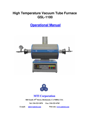
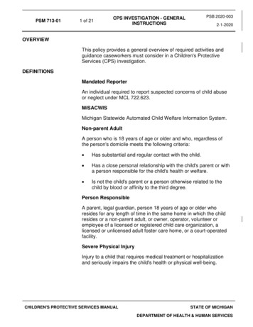
System Features and FunctionsThe front of the TRANSTECH II cabinet contains the control panel, the fluid fill neck for adding newtransmission fluid, and the fluid level windows. Because the single solenoid TRANSTECH II &TRANSTECH III share the same internal components, all further images will be of the TT III.NOTE: The TRANSTECH II has a steel cabinet and no external pressure gauge.TRANSTECH II & IIIP/N 200-8243Rev. N/A, 2003
The front of the TRANSTECH III cabinet contains the control panel, the fluid fill neck for adding newtransmission fluid, an external gauge for reading transmission cooler line pressure, and the fluid levelwindows. NOTE: The TRANSTECH III cabinet is made of a plastic composite.TRANSTECH II & IIIP/N 200-8243Rev. N/A, 2003
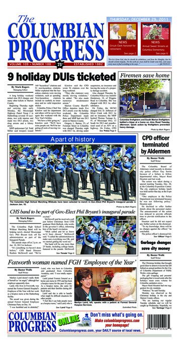
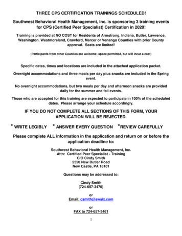
Front View - Control Panel Features andFunctionsAGBHCDEFIJA.Change FluidBegins service - Starts exchanging new fluid for used fluid. NOTE: WithDRAIN, FILL, and ENGINE START light on, service is in progress.B.DrainC.Low Vehicle FluidDrains fluid from vehicle’s transmission. When performing filter change,an alarm will sound when the transmission is empty.Illuminates when fluid from the vehicle in service is low or empty.D.CompleteIlluminates when service is complete or the stop button has been pressedE.Engine StartFlashes when the vehicle’s engine needs to be started,Is on solid when the vehicle’s engine is running and good flow is seen fromthe transmission.FEngine StopFlashes when the vehicle’s engine needs to be stopped,Is on solid when the vehicle’s engine is OFF.G.Fill (Top Off)Adds fluid to the transmission. See page 1-5 for more information.H.Low Clean FluidIlluminates when clean fluid in the unit’s clean tank is empty.I.J.StopEmpty WasteStops alarm if alarm is sounding.Stops pump if alarm is not sounding.Empties used waste fluid from unit’s waste tank.TRANSTECH II & IIIP/N 200-8243Rev. N/A, 2003
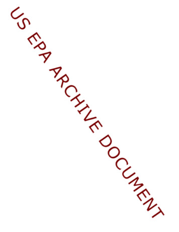
Left ViewDEAFBCA.Adapter TrayStores machine’s service adapters.B.Disposal hoseIs inserted into the shop’s fluid recycling container or into a suitablecontainer for proper disposal of used transmission fluid.C.Quick CouplerSecures the unit’s Return hose connection to the adapter connectedto the vehicle's transmission‘s cooling system.D.Fill neckAccess for filling new transmission fluid into unit’s clean tank.E.Return HoseConnects to the transmission through its cooling system.F.Disposal hosecheck ValvePrevents excessive drainage from waste hose, opens automaticallywhen EMPTY WASTE button is pushed.TRANSTECH II & IIIP/N 200-8243Rev. N/A, 2003
Right ViewCABDA.Output HoseConnects to the transmission’s cooling system.B.Quick CouplerSecures the unit’s output hose connection to the adapter connectedto the vehicle's transmission’s cooling system.C.Serial plateIdentifies the unit’s model and specific manufacturer’s productionnumber.D.Battery CablesPositive (red) and negative (black) battery connections.TRANSTECH II & IIIP/N 200-8243Rev. N/A, 2003
Theory of OperationsDescriptions of the various operations, control buttons, and indicators that make up the control panel are listedbelow.OFF MODE: When the unit is connected to power, an alarm will sound indicating power-up, and the ENGINESTART light will be flashing. When the vehicle is started, (and the hoses are connected to the vehicle), the unit will sound an alarmindicting that fluid and pressure from the vehicle have reached the machine and the ENGINE STARTlight will go steady on. It is now ready for service.SERVICE MODE: Push DRAIN button to perform a drain pan service on vehicle. The unit will automatically directthe used fluid from the vehicle’s transmission into the unit’s WASTE tank until the transmission isempty. Refer to the Transmission Filter Change on page 4-4. Push CHANGE FLUID button to perform a fluid exchange. The unit will direct the used fluidfrom the vehicle’s transmission into the unit’s WASTE tank, and supply an equal amount of new fluidfrom the unit’s CLEAN tank into the transmission. During the service the DRAIN, FILL andENGINE START lights will be on steady.DRAIN MODE: After service is complete, (COMPLETE light is on and LOW CLEAN FLUID light is on), iftransmission level needs to be lowered, push the DRAIN button. Fluid will drain only as long asthe button is pressed, flow will stop when the button is released.FILL (TOP OFF) MODE: Push FILL button after service is complete (or COMPLETE light and LOW CLEAN FLUIDlight are on, see step below). Fluid will flow into the vehicle’s transmission only as long as button ispushed. Unit has a two-quart reserve below the ‘0’ mark on front of unit.If pressed at beginning of, or during service, feature will not work (Alarm will beep). You mustfirst have the COMPLETE light on. To get a COMPLETE light when not doing a service (engine off),first RESET the battery connections, then push the CHANGE FLUID button, the unit will beep threetimes, then push the STOP button. The COMPLETE light will now be on.EXAMPLE: When checking the transmission’s fluid level before beginning the service, and thelevel in the transmission is ½ of a quart or more low, to TOP OFF you must first get the completelight on (see step above). Then push the FILL button until the correct level is reached on thetransmission dipstick and then push the STOP button. The alternative action would be for thetechnician to add the correct amount of fluid manually to the transmission, before beginning theservice.TRANSTECH II & IIIP/N 200-8243Rev. N/A, 2003
LOW CLEAN FLUID: The light will be on when the CLEAN FLUID tank is empty down to the zero mark.COMPLETE: The COMPLETE light will turn on at end of service or when the STOP button is pressed during theservice. The unit will automatically revert to bypass mode.ENGINE START: The light will flash if the engine needs to be started or if fluid flow from vehicle needs increased. The light will be on solid when the engine is running indicating good flow from the vehicle.ENGINE STOP: The light will flash if the engine needs to be stopped/turned off. After the engine is stopped/turned off, the light will be on steady.EMPTY WASTE:The light will be on when the used fluid in the WASTE tank needs to be emptied. The unit will lock outall functions until the EMPTY WASTE button is pushed allowing the waste tank to empty.STOP: Will turn off an alarm without stopping the machine when an alarm sounds during the CHANGEFLUID mode (when pushed only once). Will stop the pump and revert the system to bypass mode and clear the memory (with the alarmsounding) when pushed twice in succession or when pushed without the alarm sounding.NOTE: If the unit needs to be stopped completely while an alarm is sounding, press the STOP buttonTWICE. The first press will stop the alarm and the second press will stop the pump.TRANSTECH II & IIIP/N 200-8243Rev. N/A, 2003
Safety Information andPrecautions/!\ DANGERVehicle exhaust gases contain Carbon Monoxide, which is a colorless and odorless lethal gas.Only run engines in well-ventilated areas and avoid breathing exhaust gases.Extended breathing of exhaust gases will cause serious injury or death./!\ WARNINGExhaust gases, moving parts, hot surfaces are present during and after the vehicle’s engine is running.Read and understand the operator’s manual before using the TRANSTECH Service system.When using petroleum products always refer to the MSDS sheets and manufacturer’s instructionsfor the proper procedure to handle emergency medical treatment, cleanup, handling, and storagerequirements.Improper use of the TRANSTECH Transmission Service System or exposure to exhaust gases can cause injury.Spilled transmission fluid on an engine can ignite.Avoid exposure to flames, sparks, hot engine parts, and other ignition sources.Always keep fully charge fire extinguisher nearby. The extinguisher should have a class B ratingand be suitable for gasoline, chemical, and electrical fires.Cleanup any oil spills immediately.Dispose of contaminated cleanup material according to governing environmental laws.Never look directly into the air induction plenum or carburetor throat when the engine isoperating.Always verify hose connections to the transmission’s oil cooler lines before starting the vehicle’sengine.Explosion or flame or exposure to flammable liquid and vapors can cause injury.Flammable liquid (transmission fluid) can splash out of reservoir when filling or when unit is being moved.Always keep Reservoir Cap secure except when filling reservoir.Explosion or flame can cause injury.Transmission cooling systems may maintain residual pressure in connection lines to and from transmission andcooler radiator even after the engine has been turned off.Wear safety goggles.Wear chemical resistant gloves when connecting or disconnecting fitting and adapters.Chemicals can cause harmful byproducts - do not add any chemicals to TRANSTECH’s reservoir tank.TRANSTECH II & IIIP/N 200-8243Rev. N/A, 2003
Use only approved automatic transmission fluid.Do not swallow or ingest any chemicals.Use with adequate ventilation. Avoid breathing vapors.Do not store chemicals in or on the machine (other than automatic transmission fluid).Improper use of transmission fluid can cause injury.Over exposure can have harmful effect on eyes, skin, respiratory system and possible unconsciousness andasphyxiation.Improperly blocked vehicles can move.Set the parking brake and chock the wheels.Moving vehicles can cause injury.Moving engine parts.The engine cooling fan will cycle on and off depending on the coolant temperature and could operate without theengine running.Wear safety goggles.Always keep objects, clothing, and hands away from the cooling fans and engine parts.Moving engine parts can cause injury.Hot surfaces are present during and after running the engine.Do not contact hot surfaces such as, manifolds, pipes, mufflers, catalytic converters, or radiatorsand hoses.Hot surfaces can cause injury.Catalytic converters become extremely hot.Do not park a converter-equipped vehicle over dry grass, leaves, paper, or any other flammablematerial.Do not touch a catalytic converter until the engine has been off for at least 45 minutes.Catalytic converters can cause burns.Cracked fan blade can become airborne.Examine fan blades for cracks. If found, do not service the vehicle.Flying objects can cause injury.Batteries produce explosive gases and can explode, resulting in injury.Wear safety goggles when working on or near batteries.Use in a well-ventilated area.Keep sparks and flames away from the battery and never lay tools, equipment, or otherconductive objects on the battery.When is connecting to the battery, make sure the unit’s power switch is off. Connect the positivelead of the unit to the positive lead battery first; connect the negative lead of the unit to a solidground point as far from the battery as possible.Keep battery acid away from skin or eyes. In case of eye contact, flush with clean water for 15minutes and get medical attention.TRANSTECH II & IIIP/N 200-8243Rev. N/A, 2003
Notes:TRANSTECH II & IIIP/N 200-8243Rev. N/A, 2003
Before You Begin First Time OperationAnytime Units Waste Tank Is Completely EmptiedNOTEThis unit has been tested with Dextron lllAutomatic Transmission Fluid, and is ready forservice after receiving inspection of the unit.Use new oil above 50 degrees Fahrenheit.Remember to send in your warranty card.1.Check the output/return hoses, battery connections, and all external components for damage.2.Fill the unit’s reservoir with a minimum of 14 quarts of new transmission fluid if you are goingto perform a service now. Otherwise use 8 quarts.NOTE: Do not leave oil standing above the 0 line of either tank overnight.3.Connect two compatible adapters to each other, secure tightly. Attach the output/return hosestogether using the connected adapters (After removing the male to male liquid adaptor from eachof the units hoses if fresh out of shipping box).4.Insert the Disposal hose into the unit filler neck (or into a suitable container if the unit has beenused to service a vehicle previously).5.Attach the unit’s positive battery clip to vehicle’s 12-volt battery; connect the black ( ) batteryclip to a solid ground point as far from the battery as possible.6.Press and release the CHANGE FLUID button to start the pump. Allow the unit to pump 4 quartsof transmission fluid into the waste tank, then press STOP.NOTE: Pump will pause, then run at medium speed until STOP is pressed.7.Press the EMPTY WASTE button, let unit run until it stops automatically.8.Press the DRAIN button several times to release pressure within the output/return hoses.9.Disconnect power to machine and check new transmission fluid level, add if necessary.10.The unit is now ready to perform a service. See service instructions for procedure.-NOTESteps 3-8 must be performed BEFORE first timeoperation and/or any time the unit’s waste fluidreservoir is completely drained of fluid.TRANSTECH II & IIIP/N 200-8243Rev. N/A, 2003
Transmission Service ProcedureFollow the steps below to connect the unit to the vehicle's transmission cooler lines.Make sure the vehicle has at least 1/8 tank of fuel before beginning this process.IMPORTANTDo not perform the transmission service if thevehicle’s engine oil or coolant level is low.If necessary, add motor oil and/or coolant.Do not perform service if new transmission fluidis below 50 degrees Fahrenheit./!\ WARNINGFlammable Liquid can squirt out of pressurized lines when connecting or disconnecting.Verify that engine and machine are both off before connecting or disconnectingcooler lines or adapters.Wear safety goggles.Wear chemical resistant gloves when connecting or disconnecting fittings andadapters.Wrap a shop towel around pressure fittings and adapters when disconnecting.Avoid exposure to flames, sparks, hot engine parts, and other ignition sources.Explosion or flame or exposure to flammable liquid and vapors can cause injury.TRANSTECH II & IIIP/N 200-8243Rev. N/A, 2003
1.Add the correct amount of automatic transmission fluid into the TRANSTECH’S clean tank reservoir. Seechart below:APPROXIMATED FLUSH CHART4 Cylinder vehicle6 Cylinder vehicle8 Cylinder vehicle2.3.4.10-12 quarts12-14 quarts14-16 quartsNOTE: Quantity of fluid used per vehicle may vary depending on the condition of the fluid in thetransmission being serviced. Trucks and Step Vans may have a larger transmission, therefore may use morefluid than specified in this chart.Start engine, let run until it reaches operating temperature, turn engine OFF.Locate and disconnect the cooler line at the easiest connection point:a)At cooler line connection to radiator. Connection is usually accessible from the top corner of theradiator (could be on either top side).b)At clamped rubber hose connection to transmission cooler (connections are usually accessiblefrom the under side of the vehicle (cooler is usually in front of radiator).c)At cooler line connecting to the transmission.Connect the FLOW DIRECTION INDICATOR LOOP (‘H’ adapter) to the previously attached cooler lineadapters. Verify that the male to male quick di
Extended breathing of exhaust gases will cause serious injury or death. /!\ WARNING Exhaust gases, moving parts, hot surfaces are present during and after the vehicle’s engine is running. Read and understand the ope