Transcription
MCTCPRINCIPLESOFOPERATION4 Faran St., P.O.Box 13189, 8122503 Yavne, ISRAELTel.: 972-8-6599000 Fax: 972-8-9420858www.magnus-eng.com info@magnus-eng.com
Table of Contents1.GENERAL51.1.System Benefits61.2.Hardware Implementation Schemes81.3.Multiple Levels of Testing Automation101.4.Supported Platforms101.5.Development Tools101.6.Software Quality Assurance101.7.Connectivity to External Data Acquisition Systems111.8.Current Installations12DESIGN PRINCIPLES132.2.1.Ease of Operation132.2.Robustness132.3.Dynamic Configuration132.4.Continuous Monitoring For Limit Violations142.5.Standard Graphic User Interface143.SYSTEM FUNCTIONS143.1.User Authorization Functions153.2.Dynamic Test Cell Definition Functions153.3.Engine Run initiation Functions153.4.Engine Test Run Functions163.5.Engine Run Termination Functions163.6.Post Run Analysis Functions174 Faran St., P.O.Box 13189, 8122503 Yavne, ISRAELTel.: 972-8-6599000 Fax: 972-8-9420858www.magnus-eng.com info@magnus-eng.com
3.7.Off Line Archiving Functions173.8.Test Cell Maintenance Functions173.9.MCTC Maintenance Functions174.4.1.TEST CELL DEFINITION (DEF UTILITY)Static definitions18184.2.Parameters4.2.1.Acquired Parameters4.2.2.User Input Parameters4.2.3.System Parameters4.2.4.Output (Control) Parameters4.2.5.Derived (Calculated) Parameters1919202021224.3.25Engine states4.4.Engine Limits4.4.1.Simple Limits4.4.2.Complex Limits2727294.5.Schedules/Graphic elements314.6.Parameters' Lists334.7.Faults/Warnings354.8.Control Functions (output operation)374.9.Safety Alarms374.10.Display Screen Layout384.11.Run reasons / Run types394.12.Test Procedures435.ENGINE TESTING PROCEDURES485.1.Test Run initiation485.2.Test Run execution515.3.Test Run termination546.6.1.POST-RUN ANALYSIS FUNCTIONSArchive Access facility4 Faran St., P.O.Box 13189, 8122503 Yavne, ISRAELTel.: 972-8-6599000 Fax: 972-8-9420858www.magnus-eng.com info@magnus-eng.com5656
6.2.Single Run reports586.3.Graph generation626.4.Playback utility (the Analyzer)634 Faran St., P.O.Box 13189, 8122503 Yavne, ISRAELTel.: 972-8-6599000 Fax: 972-8-9420858www.magnus-eng.com info@magnus-eng.com
1. GENERALMagnus Computerized Test Cell system (MCTC) is a powerful genericsoftware package that provides all the data acquisition and dataprocessing functionality required for the operation of automated enginetest cells.The rest of this section and the following paragraphs provide a broaddescription of the overall capabilities of the MCTC software package.Specific implementations utilize a subset of these capabilities to generatea system which meets the monitoring, control and data processing needsof specific test cells and specific engine types.For some engine types, the generic software package is complementedwith engine specific software code that performs engine-specific complexdata processing functions. The user and run summary reports may alsobe customized to meet specific users’ needs.4 Faran St., P.O.Box 13189, 8122503 Yavne, ISRAELTel.: 972-8-6599000 Fax: 972-8-9420858www.magnus-eng.com info@magnus-eng.com
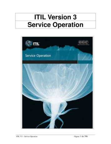
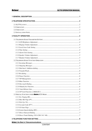
Figure 1-A: MCTC implementation for F100-PW-229 engine.1.1.System BenefitsThe implementation of a computerized Test Cell system in general and MCTC inparticular provides significant benefits to any organization which maintains and testsengines. Improved engine reliability: By ensuring complete and accurate execution of testprocedures, MCTC increases the reliability of engines that have been successfullytested in the test cell. Automated validation of required enginebehavior/performance provides additional level of reliability by eliminating thepossibility of human errors. Increased testing efficiency: MCTC can perform any required computationalmost instantaneously. Using the extensive set of functions provided by the TestBuilder facility, test procedures can be optimized so that they will be executed in a4 Faran St., P.O.Box 13189, 8122503 Yavne, ISRAELTel.: 972-8-6599000 Fax: 972-8-9420858www.magnus-eng.com info@magnus-eng.com
minimal period of time – thus allowing the most efficient (yet complete) execution ofthe required tests. The increased efficiency means faster turnaround time as wellas fuel savings (by minimizing time of maximum-power engine operation). Prevention of operational mistakes: By including proper instructions to theoperators, and a matching set of automatic tests, the testing procedure can reducethe risk of an operational mistake being made by a non-experienced operator. Ifsuch a mistake does occur, appropriate additional instructions and checks may beadded by the user (with no need of any additional programming!) to prevent similarfuture events. Avoid engine limit violations: MCTC provides continuous engine limit-violationtracking. This set of checks can be easily expanded to include early warnings –which will alarm the operator before an engine limit has been violated (e.g. if anengine may operate above a given temperature for 12 seconds, set ALARM After 4seconds above limiting temperature). This will prevent engine damage, and willeliminate unnecessary maintenance activity. Avoid unnecessary engine runs: By recording the entire run session, andcombining this data with MCTC powerful playback and analysis tools, MCTC allowsthe user to extract maximum information from any test session. In many cases thiswill enable the user to fully analyze the source of any problem detected during therun – thus eliminating the need for additional test runs. Single focus of attention: By allowing complete integration of engine and testcell facilities data (monitoring and control functions) into a single system, MCTCenables the operator to focus his/her attention on a single system (in comparison, inother test cell set ups the operator must concurrently pay attention to many differentsystems/displays). This feature enhances easier as well as safer test celloperation.4 Faran St., P.O.Box 13189, 8122503 Yavne, ISRAELTel.: 972-8-6599000 Fax: 972-8-9420858www.magnus-eng.com info@magnus-eng.com
1.2.Hardware Implementation SchemesMCTC modular design enables two basic implementation schemes:- A simple and compact implementation where all the functions of the system arecarried out on a single computer.- A complex, expanded implementation where the system’s functions are distributedbetween two independent but coordinated computers: DAC (Data Acquisition Computer): performs basic data acquisition functions.MTC (main Test Cell computer): performs all other test cell functions.The first implementation scheme is used for relatively simple engines with a smallnumber of tracked parameters (e.g. diesel engines) whereas the secondimplementation scheme is used for more complex engines with many trackedparameters and complex data processing requirements (e.g. turbo-jet and turbo-fanengines).The system capabilities can be further extended in a modular fashion by adding oneor more of the following optional components:- ESMC (Engine Shop Manual Computer): This computer displays the originalvendor testing instructions. The MTC will automatically instruct this computer todisplay the applicable section of the vendors’ documentation according to thecurrentteststep.Figure 1-A above depicts the control room of a test cell with a complex MCTCimplementation including DAC, MTC and ESMC systems.- RVC (Remote Viewing Computer): An installation of MCTC on a remote PCconnected to the MTC via standard network interface (Internet or intranet) whichallows the remote user to view the engine run in real time and view, collect andanalyze the run data independently of the test cell computers. (An on-line chat withthe test cell operator is also provided).- OADC (Offline Analysis and Development Computer): An installation of MCTC ona remote computer that may be connected to one or more test cell computers (MTCs). This component allows a test cell engineer to perform in-depth analysis of testruns from a number of different cells, and to develop and change testing procedures4 Faran St., P.O.Box 13189, 8122503 Yavne, ISRAELTel.: 972-8-6599000 Fax: 972-8-9420858www.magnus-eng.com info@magnus-eng.com
for these test cells (includes a facility to distribute newly developed definitions toconnected test cells in a controlled manner).4 Faran St., P.O.Box 13189, 8122503 Yavne, ISRAELTel.: 972-8-6599000 Fax: 972-8-9420858www.magnus-eng.com info@magnus-eng.com
1.3. Multiple Levels of Testing AutomationMCTC supports a wide range of testing automation levels:- Monitoring: MCTC Acquires, displays and stores all engine and test cellparameters. User performs “unguided” test procedures.- Test-Procedure Tracking: MCTC “guides” the user through the predefined testprocedures and performs automatic checking for successful engine operation.Actual engine control operations are executed manually.- Automatic Testing: MCTC controls the engine and the external facilities (e.g.dynamometer, fuel heating system etc.) and executes automatically predefined testprocedures.1.4. Supported PlatformsThe latest version of MCTC runs on PC's with Microsoft Windows 7 professionalOperating system. Implementations for earlier versions of Microsoft operatingsystems are also available.1.5. Development ToolsMCTC (Windows versions) was developed using the following tools:-Microsoft Visual Basic .Microsoft ACCESS .Additional third party components include (partial list):-BPS Graphic Server Version 5.0XCEED Zip Compression Library .National Instruments NI-DAQ Driver packageNational Instruments NI-488.2 Dos/Windows for AT-GPIB/TNTDIGI International DIGIBOARD Intelligent board driverIOTECH VISUALAB GUI .1.6. Software Quality Assurance4 Faran St., P.O.Box 13189, 8122503 Yavne, ISRAELTel.: 972-8-6599000 Fax: 972-8-9420858www.magnus-eng.com info@magnus-eng.com
MCTC was developed under the guidelines of MIL-STD-2167. The developmentprocess as well as the on-going maintenance of this software package isaccompanied by a software quality assurance program under the guidelines of DODSTD-2168. The quality assurance procedures and their implementation has beenreviewed and approved by various external agencies (Israel Standards Institute –ISS, Israel Air Force – IAF, P&W software quality assurance group).1.7. Connectivity to External Data Acquisition SystemsMCTC has been designed to allow seamless integration of data acquired from manydifferent external sources into a unified data analysis, storage and display process.MCTC supports a large number of standard buses over which data from externalsubsystems may be received. The incorporation of a new external data acquisitionsubsystem into the MCTC framework is a very simple task.The following external data sources are currently supported by MCTC (partial list):BusOn-Board pluginGPIB(IEEE488)RS232Sample ApplicationsNational Instruments (any NIDAQ supported card)TRIGTEK Model 645A VibrationMonitor/AnalyzerGE (F110) EMSC UARTRS422RS485P&W (F100) EDU/DEEC UARTGANTNER E.BLOXX1553BARINC 429P&W (F100) DEECAPU controller-PWCPW4000 EECJT9D EECMTU TCS and CDS/CRGANTNER EGATE (data hub) TRIGTEK 686B (VibrationPLC-DirectAnalyzer).PSI (pressure scanners)PBS4100 (Vibration Analyzer)CANBUSEthernetSample ApplicationsPC-LABCARD PCL-730channel DIO card32SCAIME DMJ (thrustmeasurement)Rosemount MICROMOTION(mass flow meter) (MODBUS)GE (F110) EMSCCFM56-7 EEC4 Faran St., P.O.Box 13189, 8122503 Yavne, ISRAELTel.: 972-8-6599000 Fax: 972-8-9420858www.magnus-eng.com info@magnus-eng.com
1.8. Current InstallationsMCTC has been implemented for the following engine types (partial list):Diesel/Piston: MERCEDES-OM355, DEUTZ-F12L-413, CUMMINS, CUCV, MAN16240, MAN-16240, DEUTZ-F8L-413, MAN-40-440, ROTAX-914, AR801/802Turbo-Jet: F404-GE-100D, J85-GE-21B/C, F110-GE-100, F100-PW-100, F100PW-220, F100-PW-200DPI, F100-PW-229, J52-PW-P8, J52-PW-P408, PWC-535Turbo-Fan: CFM56-2, CFM56-3, CFM56-5B, CFM56-7B, JT8D-200, JT3D, JT9D,PW4000, PW4100, PW4400, CF34-8C, CF34-8ETurbo-Shaft/Prop: GE T700, CT-7, PT-6A Series, T64, MAKILA 1A1, T-56-A15,Tyne-MK224 Faran St., P.O.Box 13189, 8122503 Yavne, ISRAELTel.: 972-8-6599000 Fax: 972-8-9420858www.magnus-eng.com info@magnus-eng.com
2. DESIGN PRINCIPLESThe following principles guided the design of the MCTC system.2.1. Ease of OperationThe MCTC system is designed for simple and easy use. Detailed pop-up menusand "soft" switches direct the user through selection of available options.Standard color coding scheme (messages, menus, and parameters are color coded)simplifies system operation.MCTC design allows for easy adaptation of the user interface to any desiredlanguage. Currently English, Turkish and Hebrew versions exist. The systemsupports bilingual applications (e.g. system language can be changed from EnglishtoTurkishon-line).2.2. RobustnessThe system protects itself against user errors as well as hardware malfunctions (e.g.noise on input communication lines, failure of external data acquisition devices etc.)and will automatically recover from such errors and continue to function properly.In the 2-computer implementation, the Data Acquisition computer (DAC) can runindependently of the Main Test Cell Computer (MTC) and will continue to operate ifthe MTC fails during an engine test run.2.3. Dynamic ConfigurationA major design goal for MCTC is to achieve the maximal separation betweensoftware code and the data definitions which are unique to a specific test cell andengine type. By allowing dynamic modifications of these data definitions, MCTCbecomes a generic package which can be adapted very easily to different test cellsand different engine types. The end user can modify the MCTC package to adapt itto ongoing changes in the test cell or in engines’ vendors test instructions – with noneed for additional software programming.Additionally, MCTC is usually set up with (many) spare physical input channels inorder to provide for future expansion in data acquisition capacity - again with noneed for any additional programming.4 Faran St., P.O.Box 13189, 8122503 Yavne, ISRAELTel.: 972-8-6599000 Fax: 972-8-9420858www.magnus-eng.com info@magnus-eng.com
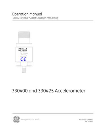
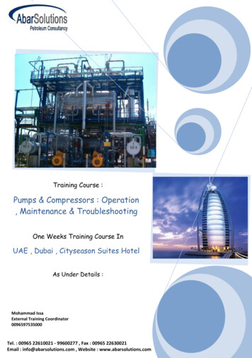
2.4. Continuous Monitoring For Limit ViolationsMCTC has been designed to continuously monitor incoming data in order torecognize engine limit violations and engine or test cell faults. All recognized enginelimit violations or faults are immediately displayed on the screen, and are alsostored and archived as part of the historical run data file. The same mechanism isused to generate early alarms – which enable the operator to avoid actualoccurrence of engine limit violation.2.5. Standard Graphic User InterfaceThe MCTC runs under the familiar Microsoft Windows environment with thestandard use of functional keys, icons and pointing device operation. As a rule,maximum usage is made of the pointing device (“mouse”) to facilitate easy and userfriendly system operation. However, most “mouse” functions can be also executedwith specific keyboard combinations to allow the experienced operator a quickermode of operation.3. System FunctionsFigure 3-A describes the main menu of the MCTC functions.Figure 3-A: Main Menu of MCTC.4 Faran St., P.O.Box 13189, 8122503 Yavne, ISRAELTel.: 972-8-6599000 Fax: 972-8-9420858www.magnus-eng.com info@magnus-eng.com
The system provides the following basic functions (key concepts and functions aredescribed in more detail in the following sections):3.1. User Authorization Functions- Update list of authorized Users- View/Report Contents of Tracked Events log file- Erase Contents of Tracked Events log file.3.2. Dynamic Test Cell Definition Functions-ParametersEngine StatesEngine LimitsOutput operationsSchedules/Graphic elementsParameters’ ListsFaults/WarningsControl Functions (output operations)Safety AlarmsDisplay Screen Layouts.Run reasons/Run TypesTest Procedures.New version generation procedureTest Cell definition reports3.3. Engine Run initiation Functions-Engine identificationRun reason(s) identificationRun type selection.Operator(s) identification.Modification of dynamic run time properties.Engine specific run initialization functions4 Faran St., P.O.Box 13189, 8122503 Yavne, ISRAELTel.: 972-8-6599000 Fax: 972-8-9420858www.magnus-eng.com info@magnus-eng.com
3.4. Engine Test Run Functions-Data initializationData acquisitionData FilteringData storageLimit violation monitoring/treatmentEngine Faults monitoring/treatmentReal time Parameter DisplayDisplay of safety alarmsUser controlled recording modes (Normal/Transient/Static)On-Line modifications of Display ScreensUser-input data processingTest Procedure trackingGeneration of System ParametersAutomatic Test control (output operations)Manual test control (output operations)Event recording (Limits, Faults, Test-procedure events)Engine specific run time functions.3.5. Engine Run Termination Functions-Display of previous tests (run-continuations) resultsUser defined run-continuation statusUser Defined final test statusUser defined remarks (free text)Generation of run reportsArchiving of run dataEngine specific run-termination functions4 Faran St., P.O.Box 13189, 8122503 Yavne, ISRAELTel.: 972-8-6599000 Fax: 972-8-9420858www.magnus-eng.com info@magnus-eng.com
3.6. Post Run Analysis Functions- Select and display historical runs based on various criteria.- Full Playback of a saved run.- Report Generation for a single saved run data.- Graphs generation for a single saved run data.- Report generation for a selected group of runs.- Trending analysis (“health monitoring”).- Exporting of run data into external formats (ASCI files,spreadsheets) to enable connection to external analysis tools.Excel3.7. Off Line Archiving Functions- Move Archived runs data files to Off-Line storage media.- Restore Archived runs data from Off-Line storage media.3.8. Test Cell Maintenance Functions- Computerized Calibration Utility.- Off-Line display of external systems’ data (e.g. PLC).-Probes/Thermocouples configuration management.3.9. MCTC Maintenance Functions- Automatic daily backup of MCTC databases.- Repair & Compact utility for MCTC databases.- Optional restoration to any stored (older) version of thecell definitions.- Complete system backup (on removable magnetic media).- System recovery procedure.4 Faran St., P.O.Box 13189, 8122503 Yavne, ISRAELTel.: 972-8-6599000 Fax: 972-8-9420858www.magnus-eng.com info@magnus-eng.comtest
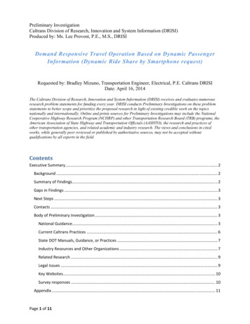
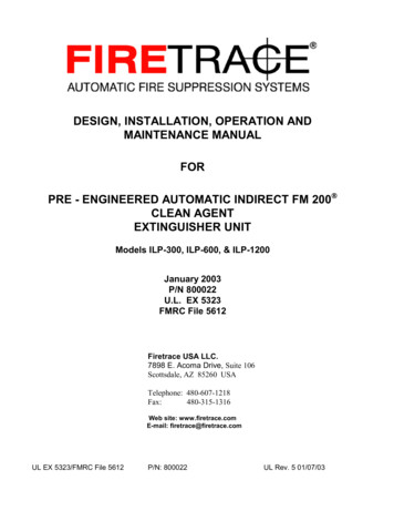
4. TEST CELL DEFINITION (DEF Utility)4.1. Static definitionsFor each implementation of MCTC, the following entities are predefined: External Data Sources for each engine type.These entities cannot be modified by the end user (as any change here entailssome hard-coded software changes). All the other entities which make up the testcell definition may be modified by the end user (including addition of a new enginetype), as described below. A separate set of definitions is used for each engine type.Therefore the [authorized] user has to select a specific engine type in order to viewand possibly modify the current definitions.Figure 4.1-A displays the entry screen of the DEF (Definition) utility, with a list ofengine types defined for the (sample) test cell.Figure 4.1-A: Test Cell Definition utility (DEF) entry screen.4 Faran St., P.O.Box 13189, 8122503 Yavne, ISRAELTel.: 972-8-6599000 Fax: 972-8-9420858www.magnus-eng.com info@magnus-eng.com
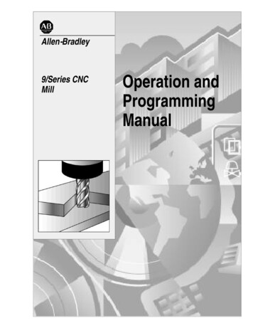
4.2. ParametersMCTC combines information from various sources into a single logical record. Thisrecord is called “a global scan” (or “scan”) and includes the values of all inputparameters in a given point in time. The user can view and modify various attributesof the system parameters using the DEF utility. Figure 4.2-A displays theParameters Update screen of the DEF utility.Figure 4.2-A: Parameter Update screen of the DEF utility.MCTC handles parameters whose values are generated either externally orinternally. The following parameter source types are supported:4.2.1. Acquired Parameters4 Faran St., P.O.Box 13189, 8122503 Yavne, ISRAELTel.: 972-8-6599000 Fax
DESIGN PRINCIPLES 13 2.1. Ease of Operation 13 2.2. Robustness 13 2.3. Dynamic Configuration 13 2.4. Continuous Monitoring For Limit Violations 14 2.5. Standard Graphic User Interface 14 3. SYSTEM FUNCTIONS 14 3.1. User Authorization Functions 15 3.2. Dynamic Test Cell Definition