Transcription
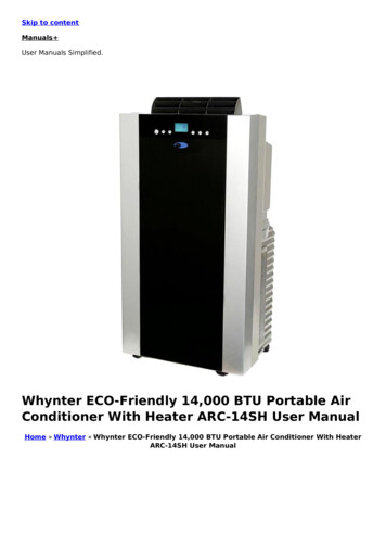
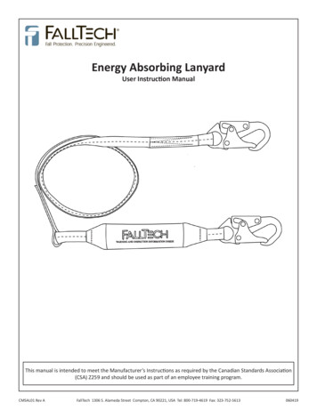
FiTechTMNote: These kits are notlegal for use on pollution controlled vehiclesFuel InjectionInstruction Manualfor the following Go EFI System37001 - Retro LS EFI SystemPlease read the full instructions before beginning your installation. system. For technical assistance with your Retro LS Kit,These instructions cover the basic kit installation and setup. Failure call the FiTech EFI Tech Line at (951)340-2624to follow these instructions may result in malfunctioning of theWarning: Caution must be observed when installing any productinvolving fuel system parts. Work in a well ventilated area with anapproved fire extinguisher readily available. Eye protection andother safety apparel should be worn to protect against debris andsprayed gasoline. We recommend having this installation per-formed by an experienced, qualified, automotive technician. Thefinished installation must be thoroughly checked for any fuel system leaks. All safety precautions must be observed when workingwith fuel. Disconnect the battery ground wire (-) before startingthe installation.Retro LS Kit 37001KIT CONTENTS(1) 4-injector throttle body with ClassicCarburetor Gold finish.(4) inlet/outlet port plugs (Installed on throttlebody)(1) Main Harness(1) ECU(1) 1/2" NPT to 3/8" NPT Reducer(4) Injectors pre-installed(1) Idle Air Control (Pre-Installed)(1) Throttle Position Sensor (Pre-Installed)(1) MAP Sensor (Pre-Installed)(1) Wide Band O2 Sensor(1) Clamp on O2 Bung Kit(1) Handheld Controller with billet case(1) Windsheild Mount for Controller(1) -06 AN crossover hose with -6AN maleinlet fitting (Pre-Installed)(1) Gasket kitAFigure 1Table of ContentsKit contentsAbout your Go EFI Retro LS KitSpecial instructionsEngine protection feature VacuumPortsThrottle Body InstallationWide Band O2 Sensor InstallationAir LeaksInstalling the Harness12222,33344MAPIACTPSCTSImportant SensorsCoolant Sensor InstallationInjectorsWiring the EFI SystemOn-Engine Adjustments1444456666IAC setupHandheld Controller InitialProgrammingFan SetupWire ChartFuel Delivery RequirementsFuel Delivery schematic67778910
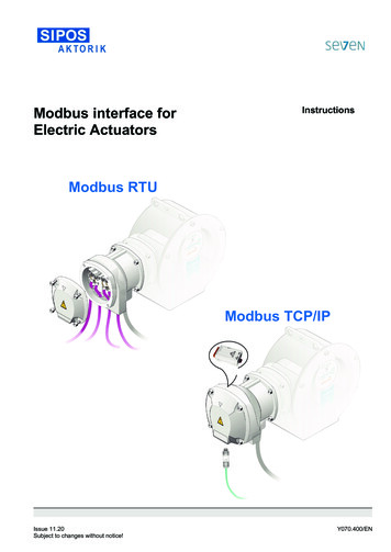
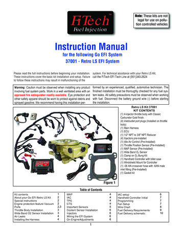
About your FiTech Go EFI Retro LS SystemCONGRATULATIONS on your purchase of the FiTech EFI System! TheRetro LS Kit will bolt directly to any 4-BBL Intake Manifold. To fit on aspread bore 4-BBL manifold requires an inexpensive adapter plate toavoid leaks. Suitable adapter plates are available from severalsuppliers such as Summit Racing. . The Retro LS Kit is self-tuning oncethe initial setup is performed using the hand-held controller. When thenecessary initial inputs are made with the hand-held controller theEFI System creates a base fuel map to get the enginerunning. Then the self-tuning programming will fine tune the map toproduce optimum power and performance. Through the use of a WideBand O2Sensor the system can continuously make adjustments in the fueldelivery to provide the correct air/fuel ratio under all climate andaltitude conditions. Several sensors are also integrated in the throttlebody assembly including the Throttle Position Sensor (TPS), and theManifold Absolute Pressure Sensor (MAP). The Wide Band O2 Sensor isinstalled into the exhaust pipe. This system is designed with safety inmind and has a self adjusting “limp home” mode. It also has a datalogging feature to track what is going on with the system while it isrunning, to ensure optimal performance.Special instructionsThe Retro LS Kits are intended for use with unleaded pump gas.Make sure that you remove ALL low pressure hoses, fittings and clamps The system is compatible with E-85, but this requires advancedon factory fuel lines and replace them with EFI rated fuel hose. Also the tuning knowledge. Maximum horsepower fueling capacity is reduceduse of proper flared connections and clamps is a necessity. Be careful by approximately 30% with E-85. Fuel system components shouldnot to mix 45 and 37 AN fittings, they look similar but will not work be E-85 compatible and in new condition to prevent sludge fromtogether. 45 fittings usually come from a hardware store or autobreaking loose.parts store while 37 AN fittings are the ones supplied by FiTech andThe Retro LS Kit is designed to be used with all the LS basedmost speed shops.motors, it uses Cam and Crank sensors for optimum timing control.Cranking fuel and hard throttle hits (accelerator pump) are tuned by This system is NOT smog legal.the user. Selecting the right "cam" and engine CID (Cubic Inch The Retro LS Kit comes with preinstalled 80-lb flow matchedDisplacement) during setup will get the learning closer. Cruise and wide injectors and is capable of handling up to 650 hp.open throttle (WOT), mixture (trims) are continuously learned and The Retro LS Kit does all the timing control control like thetweaked by the system.Ultimate LS Kits The Retro LS Kit needs an external fuel pressure regulator setat 58 PSI. A G-Surge containing a high pressure pump and regulatoris available (PN 40009). This serves as a fuel pressure amplifier andis fed by a low pressure mechanical/elctric pump.Always turn off ignition and allow at least 15 seconds Very important note: Your fuel tank must have a ventfor ECU to save if disconnecting batteryto prevent pressure building up inside the tank.Engine Protection FeatureThe Retro LS Kit is programmed with a "limp home mode". Thisfeature does not shut down your system, instead the ECU isdesigned to compensate if a sensor fails. This means, that if forany reason a sensor fails, that sensor will receive either a default valueor a simulated value. This is to ensure that the engine remains runningin a safe and controlled manner so that you can get to a repair facility,or to your home, to resolve the issue. Due to the compensationfeatures of the ECU, the way to check if something is goingwrong with your system, is by the faultcodes option on the main menu of your hand-held controller. The faultcode comes up under OBD-II, diagnostic standard, but to the right of thecode it will state which sensor is having the problem. A new featureprogrammed into the hand-held is a rev offset. This feature will protectthe engine from long term abuse because it lowers your built in rev limiterenable to prevent over revving and possible engine damage during warmup. It will automatically turn the feature off once your enginereaches operating temperature.Determining Use of Vacuum PortsDetermine the engine's need for vacuum ports includingported and manifold vacuum. These ports cover accessoriessuch as power brakes, vacuum advance, transmissionmodulator, PCV and possibly more. There are two 3/16" malenipples and three 3/8" male nipples. See figure 1 and 2 forlocation and use of various vacuum nipples.Very Important Note:Your fuel tank MUST be vented toprevent pressure from building upinside the tank.Extra 3/8" nipple for othervacuum accessory or cap ifnot needed.This 3/16" nipplewill provide timed(ported) vacuumThis 3/16" nipplewill provide fullmanifold vacuumFigure 22A
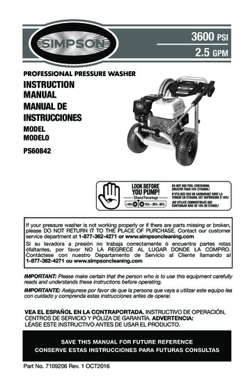
Figure 3Installing the Wide Band Oxygen (O2) SensorUse this 3/8" nipplefor PCV connection.Use this 3/8" nipplefor-power brakebooster.Installing the Throttle BodyFigure 4This is the key component of any EFI system. Only one sensor isrequired. This sensor continuously monitors the exhaust gas mixture andsends the information to the ECU where adjustments are constantly madeto maintain the air/fuel targets.1. The supplied O2 Sensor Bung can be installed in either exhaust bank.2. The Sensor connects to one of the cables in the main wiring harness.See Figure 7 on next page.3. The ideal location for the sensor is in the exhaust collector or within 8inches of the collector itself. It must always be at least 18-inches from theexhaust tip, to prevent reversion and false lean conditions.4. The sensor should be between 10 to 14 above horizontal (see figure6 below) to allow condensation to run off. If this is not adhered to, thesensor is susceptible to damage.5. Never position the sensor on the outside of a bend in the exhausttubing.6. The sensor must always be mounted ahead of any catalytic converter ifvehicle is so equipped.7. Drill a 7/8" diameter hole in the desired location.Figure 61. Place the supplied gasket on the manifold (see above) and place thethrottle body onto the gasket over the existing studs. The throttle bodylinkage must be on the driver’s side of the engine.2. Install the original nuts and washers onto the four carburetor studs.See Figure 4.3. Tighten to 10 lb. ft. of torque in several steps using a crisscrosspattern.8. The supplied bung kit can either be welded in place or clamped onto thepipe. The clamp-on style works well and will not leak. If welded, makesure the bung is welded completely all the way around and does not leak.Thread an M18-1.5 bolt into the bung to prevent distortion.9. Install the sensor into the bung. Tighten securely.10. Connect the O2 sensor to the sub-harness that connects to thethrottle body. See Figure 7.11. Note: The O2 Sensor will not work on "Zoomie" style headers.Figure 5WARNING: Do not start the engine without the sensor cable connected to the throttle body and the EFI system is fully operationalor damage will occur to the sensor!3
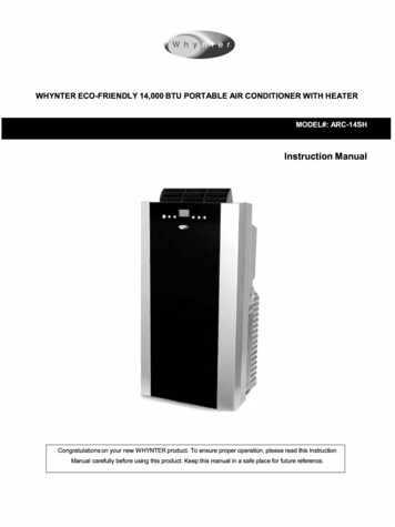
AIR LEAKS: It is important that no air leaks exist anywhere in theexhaust system, before or after the sensor, as this will cause falsereadings. This will lead to poor engine performance, including misfires,and the inability to properly auto-tune the EFI. Continued running of thesystem with an exhaust leak can create detonation and possible severeengine damage. Incorrect installation of the sensor, exhaust leaks,and any resulting damage is not covered by the FiTechmanufacturer's warranty. It is very important to ensure your exhaustis leak-free. For optimum EFI operation and function, your exhaust (onthe sensor side) must be totally secure with no leaks.Installing the Wiring HarnessFigure 79710856231214111315ECU171918Index1: ECU Conn.2: Key3: Fuel Pump4: Accessories5: HH Cables6: Fuse Box7: GroundWhen installing the harness, the external ECU can be mounted anywhere in the engine bay or through the firewall. Be sure to keep itaway from excessive heat. The harness is made up of the followingconnections: MAP, IAC, O2, TPS, CTS, FAN, CAM, KNOCK ,COIL D/P,VSS, TRANS, CKP, ALT, INJECTOR PLUG, GROUND, POSITIVE ,ECU, HANDHELD CNTROLLER, FUEL PUMP, and KEY HOT.MAP ( Manifold Absolute Pressure)- Starting with the MAP sensor, the MAPis attached to the outside of the throttle body on the passenger side. Itregulates the inlet air temperature and the manifold absolutepressure. The two sensors (inlet air temp and manifold absolutepressure) are combined for ease of installation. The TemperatureManifold Absolute Pressure measures the load on the engine andwill range between 10 and 90kPa while the engine is running. When theengine is off it will read at .Figure 8164199-100kPa. See Figure 8 below.78: VSS9: Trans Control10: Power to Bat.11: CKP12: Injector Plug13: Coil P14: Cam15: Kock16: O217: Coil D18: CTS19: ALTthrottle blades are open.Figure 9The ECU maintains thecalibration of the sensorbut, if the TPS reading isnot at 0 at idle then thesensor needs to berecalibrated. See Figure10.CTS (Coolant Temp Sensor)The Coolant Temperature Sensor cable plugs into a sensor fitted into driver side cylinderhead. It is used to measure the temperature of the engine coolant.The sensor then sends the information to the ECU to adjust fuel.See Figures 17 and 18 on page 6.IAC (Idle Air Control)The Idle Air ControlSensor gets installeddirectly into the throttlebody. It is used to control the RPM of themotor at idle. See Figure 9, above right.TPS (Throttle Position Sensor)The Throttle PositionSensor’s purpose is torecord how far theFigure 104
Coil D - Below is the proper way to install the connector labeled "CoilD" to Driver side ignition coils.CAM - Install the plug labeled "CAM" on your cam sensor which islocated in the rear of the block on LS1 or in front on LS3Figure 11Figure 14CKP - The connector labeled "CKP" is one of the mos importantconnectors in the kit, it is also the hardest to find. It is located in thepassenger side of the block (if engine is in front of vehicle and thevehicle is RWD) between the starter and the Block.Coil p - Below is the proper way to install the connector labeled "CoilP" to Passenger side ignition coils.Figure 15Figure 12ALT - Connect the plug labeled "ALT" to your alternator as shownbelow.POS - The two red wires labeled "POS" can be easily installed onthe starter where there are always 12V present.Figure 13Figure 165
Figure 17Figure 18Above - Our CTS plug is made to work with the factory OEMtemperature sensor. Replacements are also available if needed.Above - The CTS connector on the main wiring harness is pluggedinto the Coolant Temperature Sensor in cylinder head.InjectorsFigure 19Figure 20Injector sub harnessconnectorInjector sub-harnessAbove - The throttle body has four 80-lb injectors alreadyinstalled. This arrangement will allow the system to supply enough See Figure 7. Connect the injector sub-harness onto the mainfuel flow for up to 650 HP. The throttle body has the injector sub- harness. Make sure the connectors are securely fastened.harness preinstalled and ready to go.On Engine-AdjustmentsWhen you set idle speed, you will notice some new sounds. The first isticking from the injectors and it is normal. You may also hear airSee the wire chart (Figure 21 on page 8 which lists each wire inwhooshing or whistling at idle. Barring a vacuum leak, this is likely theHarness "A" that is used in the system and what it connects to.NOTE:TTypically some of the wires listed on the chart on page 8 may bypassed air from the Idle Air Control (IAC valve) and this is normal. TheIAC valve maintains idle speed when the AC compressor or electric fansneed to be extended. It is strongly suggested that any wireextensions are made with the same gauge and color wire as is used click on.in the supplied harness. Make connections as a soldered joint rather IAC Setupthan crimped connection. Utilize shrink wrapped sleeve covering all The idle screw on the throttle body needs to be adjusted. This needs to beset so that the IAC value is nearly closed when fully warmed up and inconnections.idle 3-10 IAC Steps are recommended for a fully warm engine, out of gear,at idle. When the engine is at idle, the IAC will learn the necessary positionAll modifications madetomaintain the RPM at the Target Idle Speed. When loads are placed onto wiring can onlytheengine or when the throttle is open, the IAC steps will move around,be made on wiresthisis normal. It’s best to adjust this screw from a more open position tolisted in Wire Chartstartwith. This will allow the engine to start at a high idle, which willFigure 21 on pagemakeadjusting the IAC easier. Follow this procedure:8 labeled accessoriessuch as extensions1. Start the engine and in your Handheld go under "initial set-up."or cuts. Any modifica2. Go to “idle setup” and find “idle set mode” and switch to "Adjust"tion of the ECU main3. Start the vehicle and find IAC Steps on the dashboard. This numberharness (see Figure 7)needs to be within 3-10 at operating temperature. If the number readsother than thesezero then slowly turn the screw OUT (counterclock-wise) until the IAClisted wires will resultSteps reads between 3-10.in a VOIDING of the Fan CircuitFiTech EFI warranty.Wiring the EFI System6
4. If the number is above 10, then turn the screw IN (clockwise) asstated above and repeat the process until the IAC steps are between3-10.5. When finished turn key off and allow system to save (30 seconds ofkey off), and the system will automatically shut off idle set modeNOTE: Once the IAC set up is complete no further adjustments arenecessary3. Cam Mild-Wild – Cam selection is based on vacuum load of theengine. Choose the selection that corresponds with the amount ofmanifold vacuum your engine produces at idle (in Neutral). Cam 1 is for15inHg or above, Cam 2 is for 10inHg to 15inHg, Cam 3 is 8inHg to10inHg, Cam 4 is 6inHg to 8inHg. These are estimates and you mayneed to switch between them if the vacuum load is between two differentcam settings to get the engine to run better for your application.4.Rev limit RPM – This is a fuel cut. Please set at least 200 RPM aboveHandheld Controllerthemaximum RPM you wish your engine to run to. This is not a softThere are two ways to navigate the Handheld Controller; you can usetouchrev limiter, but a built-in safety feature.the touchscreen with your finger or the joystick: up, down, left, and right.5.IdleSpeed Warm – The idle speed at which you wish your engine toThe joystick is the black button on the right hand side of your controller,runat150degrees and above. If you are using the Retro LS Kit to controlit can be used to view the displays on the Controller by moving theyourelectricfans, your idle speed will increase by 30 rpm, will be higherbutton up and down or side to side, then pressing the joystick enter.whentheengineis colder and will taper down to set speed by 1501. When making changes to the ECU through the Handheld Controller,degrees.make sure that the ignition key is on.2. Once the changes are made, turn the key off, wait 15 to 20 secondsuntil the values disappear under the "dashboard" feature. Doing this will Fan 1 SetupOn the Calibration screen, follow these steps:ensure that your changes have received a hard save.Ifusing an electric fan, go to option # 3 and select Enable , then press3. Once the hard save is completed, if desired, the vehicle battery can beEnteror depress the joystick button to send info to the ECU. If not usingdisconnected without interference with the calibrations.an electric fan, select Disable and continue the Enter/Send steps aboveNote: This step is important to eliminate a fault code from appearingInitial Programmingwhen not using an electric fan, and also eliminating the idle speed fromThis simple procedure is performed using the Handheld Controller. Aincreasing when the fan "ON" temperature is achieved and no fan islaptop computer is not required.used. If fan is enabled, follow these next steps:* This unit plugs into the throttle body ECU* Input the number of cylinders, cubic inch displacement, cam size, #1) Fan 1 ON Temp - Enter desired temperature, Enter/ depress to sendto ECU. Idle speed will increase when fan is activated. Idle speedtarget idle speed warm, fan control, RPM limit and max rev limit.increaseis not user programmable in basic calibration.* The Handheld Controller can be removed or left connected. When#2)Fan1OFF Temp - This is usually set approximately 5 degrees lowerconnected, there is a "Dashboard" and "Large Gauges" screen thatthanFanONtemperature, but is up to user preference. Note: Settingwill show engine parameters in real time. Included in your kit is amustbelowerthanfan ON temperature for fans to shut off.windshield or dash mounted bracket to hold the controller while driving.(Note: When changing values on the Handheld Controller, you mustdepress the joystick button to send your info to the ECU. You will then At this point you have made all of the selections you need to start yoursee 'Sent to ECU Succeed' message which is a confirmation that it was engine! BUT WAIT!!!!. Please turn your key to the OFF POSITION andsuccessful (Changing the number alone will not change the value in the wait for about 30 seconds for the ECU to store these changes. This is aECU). Also, all items have a factory default which may work for you – one-time setup and the changes are permanently stored in the ECUeven if you disconnect the battery! They can be changed at any time inchange only as needed!the future but no battery power is needed for the ECU to keep these1. Cylinders - Factory preset is 8 and shouldn’t need to be changed forselections in its memory.most installations.2. Engine CID – Factory preset is 326 CID. To change value you can usetouchscreen buttons (Edit, CLR value from screen, Enter your numbernow
call the FiTech EFI Tech Line at (951)340-2624 Warning: Caution must be observed when installing any product involving fuel system parts. Work in a well ventilated area with an . It also has a data logging feature to track what is going on with the s