Transcription
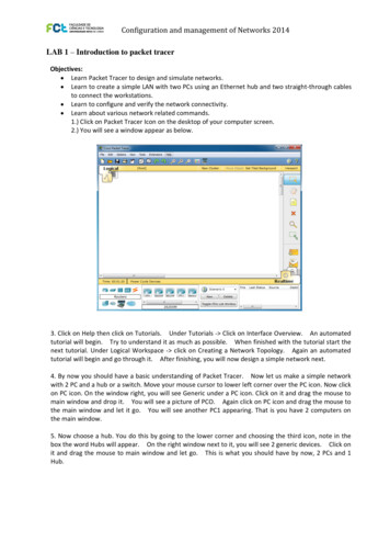
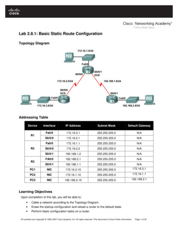
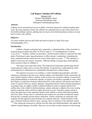
Lab 7.4.1: Basic DHCP and NAT ConfigurationTopology DiagramAddressing TableDeviceR1R2ISPInterfaceIP AddressSubnet 165.200.226255.255.255.252ScenarioIn this lab, you will configure the DHCP and NAT IP services. One router is the DHCP server. The otherrouter forwards DHCP requests to the server. You will also configure both static and dynamic NATconfigurations, including NAT overload. When you have completed the configurations, verify theconnectivity between the inside and outside addresses.All contents are Copyright 1992–2007 Cisco Systems, Inc. All rights reserved. This document is Cisco Public Information.Page 1 of 9
CCNA ExplorationAccessing the WAN: IP Addressing ServicesLab 7.4.1: Basic DHCP and NAT ConfigurationTask 1: Prepare the NetworkStep 1: Cable a network that is similar to the one in the topology diagram.Step 2: Clear all existing configurations on the routers.Task 2: Perform Basic Router ConfigurationsConfigure the R1, R2, and ISP routers according to the following guidelines: Configure the device hostname. Disable DNS lookup. Configure a privileged EXEC mode password. Configure a message-of-the-day banner. Configure a password for the console connections. Configure a password for all vty connections. Configure IP addresses on all routers. The PCs receive IP addressing from DHCP later in the lab. Enable OSPF with process ID 1 on R1 and R2. Do not advertise the 209.165.200.224/27network.Note: Instead of attaching a server to R2, you can configure a loopback interface on R2 to use the IPaddress 192.168.20.254/24. If you do this, you do not need to configure the Fast Ethernet interface.Task 3: Configure PC1 and PC2 to receive an IP address through DHCPOn a Windows PC go to Start - Control Panel - Network Connections - Local Area Connection.Right mouse click on the Local Area Connection and select Properties.Make sure the button is selected that says Obtain an IP address automatically.Once this has been done on both PC1 and PC2, they are ready to receive an IP address from a DHCPserver.All contents are Copyright 1992–2007 Cisco Systems, Inc. All rights reserved. This document is Cisco Public Information.Page 2 of 9
CCNA ExplorationAccessing the WAN: IP Addressing ServicesLab 7.4.1: Basic DHCP and NAT ConfigurationTask 4: Configure a Cisco IOS DHCP ServerCisco IOS software supports a DHCP server configuration called Easy IP. The goal for this lab is to havedevices on the networks 192.168.10.0/24 and 192.168.11.0/24 request IP addresses via DHCP from R2.Step 1: Exclude statically assigned addresses.The DHCP server assumes that all IP addresses in a DHCP address pool subnet are available forassigning to DHCP clients. You must specify the IP addresses that the DHCP server should not assign toclients. These IP addresses are usually static addresses reserved for the router interface, switchmanagement IP address, servers, and local network printer. The ip dhcp excluded-address commandprevents the router from assigning IP addresses within the configured range. The following commandsexclude the first 10 IP addresses from each pool for the LANs attached to R1. These addresses will notbe assigned to any DHCP clients.R2(config)#ip dhcp excluded-address 192.168.10.1 192.168.10.10R2(config)#ip dhcp excluded-address 192.168.11.1 192.168.11.10Step 2: Configure the pool.Create the DHCP pool using the ip dhcp pool command and name it R1Fa0.R2(config)#ip dhcp pool R1Fa0Specify the subnet to use when assigning IP addresses. DHCP pools automatically associate with aninterface based on the network statement. The router now acts as a DHCP server, handing out addressesin the 192.168.10.0/24 subnet starting with 192.168.10.1.R2(dhcp-config)#network 192.168.10.0 255.255.255.0Configure the default router and domain name server for the network. Clients receive these settings viaDHCP, along with an IP address.R2(dhcp-config)#dns-server 192.168.11.5R2(dhcp-config)#default-router 192.168.10.1Note: There is not a DNS server at 192.168.11.5. You are configuring the command for practice only.Because devices from the network 192.168.11.0/24 also request addresses from R2, a separate poolmust be created to serve devices on that network. The commands are similar to the commands shownabove:R2(config)#ip dhcp pool R1Fa1R2(dhcp-config)#network 192.168.11.0 255.255.255.0R2(dhcp-config)#dns-server 192.168.11.5R2(dhcp-config)#default-router 192.168.11.1Step 3: Test DHCPOn PC1 and PC2 test whether each has received an IP address automatically. On each PC go to Start Run - cmd - ipconfig -allWhat are the results of your test?Why are these the results?All contents are Copyright 1992–2007 Cisco Systems, Inc. All rights reserved. This document is Cisco Public Information.Page 3 of 9
CCNA ExplorationAccessing the WAN: IP Addressing ServicesLab 7.4.1: Basic DHCP and NAT ConfigurationStep 4: Configure a helper address.Network services such as DHCP rely on Layer 2 broadcasts to function. When the devices providingthese services exist on a different subnet than the clients, they cannot receive the broadcast packets.Because the DHCP server and the DHCP clients are not on the same subnet, configure R1 to forwardDHCP broadcasts to R2, which is the DHCP server, using the ip helper-address interface configurationcommand.Notice that ip helper-address must be configured on each interface involved.R1(config)#interface fa0/0R1(config-if)#ip helper-address 10.1.1.2R1(config)#interface fa0/1R1(config-if)#ip helper-address 10.1.1.2Step 5: Release and Renew the IP addresses on PC1 and PC2Depending upon whether your PCs have been used in a different lab, or connected to the internet, theymay already have learned an IP address automatically from a different DHCP server. We need to clearthis IP address using the ipconfig /release and ipconfig /renew commands.Step 6: Verify the DHCP configuration.You can verify the DHCP server configuration in several different ways. Issue the command ipconfig onPC1 and PC2 to verify that they have now received an IP address dynamically. You can then issuecommands on the router to get more information. The show ip dhcp binding command providesinformation on all currently assigned DHCP addresses. For instance, the following output shows that theIP address 192.168.10.11 has been assigned to MAC address 3031.632e.3537.6563. The IP leaseexpires on September 14, 2007 at 7:33 p.m.R1#show ip dhcp bindingBindings from all pools not associated with VRF:IP addressClient-ID/Lease expirationHardware address/User name192.168.10.110063.6973.636f.2d30. Sep 14 2007 07:33 PM3031.632e.3537.6563.2e30.3634.302d.566c.31All contents are Copyright 1992–2007 Cisco Systems, Inc. All rights reserved. This document is Cisco Public Information.TypeAutomaticPage 4 of 9
CCNA ExplorationAccessing the WAN: IP Addressing ServicesLab 7.4.1: Basic DHCP and NAT ConfigurationThe show ip dhcp pool command displays information on all currently configured DHCP pools on therouter. In this output, the pool R1Fa0 is configured on R1. One address has been leased from this pool.The next client to request an address will receive 192.168.10.12.R2#show ip dhcp poolPool R1Fa0 :Utilization mark (high/low): 100 / 0Subnet size (first/next): 0 / 0Total addresses: 254Leased addresses: 1Pending event: none1 subnet is currently in the pool :Current indexIP address range192.168.10.12192.168.10.1- 192.168.10.254Leased addresses1The debug ip dhcp server events command can be extremely useful when troubleshooting DHCPleases with a Cisco IOS DHCP server. The following is the debug output on R1 after connecting a host.Notice that the highlighted portion shows DHCP giving the client an address of 192.168.10.12 and maskof 255.255.255.0*Sep 13 21:04:18.072: DHCPD: Sending notification of DISCOVER:*Sep 13 21:04:18.072:DHCPD: htype 1 chaddr 001c.57ec.0640*Sep 13 21:04:18.072:DHCPD: remote id 020a0000c0a80b01010000000000*Sep 13 21:04:18.072:DHCPD: circuit id 00000000*Sep 13 21:04:18.072: DHCPD: Seeing if there is an internally specified poolclass:*Sep 13 21:04:18.072:DHCPD: htype 1 chaddr 001c.57ec.0640*Sep 13 21:04:18.072:DHCPD: remote id 020a0000c0a80b01010000000000*Sep 13 21:04:18.072:DHCPD: circuit id 00000000*Sep 13 21:04:18.072: DHCPD: there is no address pool for 192.168.11.1.*Sep 13 21:04:18.072: DHCPD: Sending notification of DISCOVER:R1#*Sep 13 21:04:18.072:DHCPD: htype 1 chaddr 001c.57ec.0640*Sep 13 21:04:18.072:DHCPD: remote id 020a0000c0a80a01000000000000*Sep 13 21:04:18.072:DHCPD: circuit id 00000000*Sep 13 21:04:18.072: DHCPD: Seeing if there is an internally specified poolclass:*Sep 13 21:04:18.072:DHCPD: htype 1 chaddr 001c.57ec.0640*Sep 13 21:04:18.072:DHCPD: remote id 020a0000c0a80a01000000000000*Sep 13 21:04:18.072:DHCPD: circuit id 00000000R1#*Sep 13 21:04:20.072: DHCPD: Adding binding to radix tree (192.168.10.12)*Sep 13 21:04:20.072: DHCPD: Adding binding to hash tree*Sep 13 21:04:20.072: DHCPD: assigned IP address 192.168.10.12 to .3634.302d.566c.31.*Sep 13 21:04:20.072: DHCPD: Sending notification of ASSIGNMENT:*Sep 13 21:04:20.072: DHCPD: address 192.168.10.12 mask 255.255.255.0*Sep 13 21:04:20.072:DHCPD: htype 1 chaddr 001c.57ec.0640*Sep 13 21:04:20.072:DHCPD: lease time remaining (secs) 86400*Sep 13 21:04:20.076: DHCPD: Sending notification of ASSIGNMENT:*Sep 13 21:04:20.076: DHCPD: address 192.168.10.12 mask 255.255.255.0R1#*Sep 13 21:04:20.076:DHCPD: htype 1 chaddr 001c.57ec.0640*Sep 13 21:04:20.076:DHCPD: lease time remaining (secs) 86400All contents are Copyright 1992–2007 Cisco Systems, Inc. All rights reserved. This document is Cisco Public Information.Page 5 of 9
CCNA ExplorationAccessing the WAN: IP Addressing ServicesLab 7.4.1: Basic DHCP and NAT ConfigurationTask 5: Configure Static and Default RoutingISP uses static routing to reach all networks beyond R2. However, R2 translates private addresses intopublic addresses before sending traffic to ISP. Therefore, ISP must be configured with the publicaddresses that are part of the NAT configuration on R2. Enter the following static route on ISP:ISP(config)#ip route 209.165.200.240 255.255.255.240 serial 0/0/1This static route includes all addresses assigned to R2 for public use.Configure a default route on R2 and propagate the route in OSPF.R2(config)#ip route 0.0.0.0 0.0.0.0 209.165.200.226R2(config)#router ospf 1R2(config-router)#default-information originateAllow a few seconds for R1 to learn the default route from R2 and then check the R1 routing table.Alternatively, you can clear the routing table with the clear ip route * command. A default route pointingto R2 should appear in the R1 routing table. From R1, ping the serial 0/0/1 interface on ISP(209.165.200.226). The pings should be successful. Troubleshoot if the pings fail.Task 6: Configure Static NATStep 1: Statically map a public IP address to a private IP address.The inside server attached to R2 is accessible by outside hosts beyond ISP. Statically assign the publicIP address 209.165.200.254 as the address for NAT to use to map packets to the private IP address ofthe inside server at 192.168.20.254.R2(config)#ip nat inside source static 192.168.20.254 209.165.200.254Step 2: Specify inside and outside NAT interfaces.Before NAT can work, you must specify which interfaces are inside and which interfaces are outside.R2(config)#interface serial 0/0/1R2(config-if)#ip nat outsideR2(config-if)#interface fa0/0R2(config-if)#ip nat insideNote: If using a simulated inside server, assign the ip nat inside command to the loopback interface.Step 3: Verify the static NAT configuration.From ISP, ping the public IP address 209.165.200.254.Task 7: Configure Dynamic NAT with a Pool of AddressesWhile static NAT provides a permanent mapping between an internal address and a specific publicaddress, dynamic NAT maps private IP addresses to public addresses. These public IP addresses comefrom a NAT pool.Step 1: Define a pool of global addresses.Create a pool of addresses to which matched source addresses are translated. The following commandcreates a pool named MY-NAT-POOL that translates matched addresses to an available IP address inthe 209.165.200.241–209.165.200.246 range.R2(config)#ip nat pool MY-NAT-POOL 209.165.200.241 209.165.200.246 netmask255.255.255.248All contents are Copyright 1992–2007 Cisco Systems, Inc. All rights reserved. This document is Cisco Public Information.Page 6 of 9
CCNA ExplorationAccessing the WAN: IP Addressing ServicesLab 7.4.1: Basic DHCP and NAT ConfigurationStep 2: Create an extended access control list to identify which inside addresses are translated.R2(config)#ip access-list extended NATR2(config-ext-nacl)#permit ip 192.168.10.0 0.0.0.255 anyR2(config-ext-nacl)#permit ip 192.168.11.0 0.0.0.255 anyStep 3: Establish dynamic source translation by binding the pool with the access control list.A router can have more than one NAT pool and more than one ACL. The following command tells therouter which address pool to use to translate hosts that are allowed by the ACL.R2(config)#ip nat inside source list NAT pool MY-NAT-POOLStep 4: Specify inside and outside NAT interfaces.You have already specified the inside and outside interfaces for your static NAT configuration. Now addthe serial interface linked to R1 as an inside interface.R2(config)#interface serial 0/0/0R2(config-if)#ip nat insideStep 5: Verify the configuration.Ping ISP from PC1 or the Fast Ethernet interface on R1 using extended ping. Then use the show ip nattranslations and show ip nat statistics commands on R2 to verify NAT.R2#show ip nat translationsPro Inside globalInside localicmp 209.165.200.241:4 192.168.10.1:4--- 209.165.200.241192.168.10.1--- 209.165.200.254192.168.20.254Outside local209.165.200.226:4-----Outside global209.165.200.226:4-----R2#show ip nat statisticsTotal active translations: 2 (1 static, 1 dynamic; 0 extended)Outside interfaces:Serial0/0/1Inside interfaces:Serial0/0/0, Loopback0Hits: 23 Misses: 3CEF Translated packets: 18, CEF Punted packets: 0Expired translations: 3Dynamic mappings:-- Inside Source[Id: 1] access-list NAT pool MY-NAT-POOL refcount 1pool MY-NAT-POOL: netmask 255.255.255.248start 209.165.200.241 end 209.165.200.246type generic, total addresses 6, allocated 1 (16%), misses 0Queued Packets: 0To troubleshoot issues with NAT, you can use the debug ip nat command. Turn on NAT debugging andrepeat the ping from PC1.R2#debug ip natIP NAT debugging is onR2#*Sep 13 21:15:02.215: NAT*:*Sep 13 21:15:02.231: NAT*:*Sep 13 21:15:02.247: NAT*:*Sep 13 21:15:02.263: NAT*:s 192.168.10.11- 209.165.200.241, d 209.165.200.226s 209.165.200.226, d 209.165.200.241- 192.168.10.11s 192.168.10.11- 209.165.200.241, d 209.165.200.226s 209.165.200.226, d 209.165.200.241- 192.168.10.11All contents are Copyright 1992–2007 Cisco Systems, Inc. All rights reserved. This document is Cisco Public Information.Page 7 of 9[25][25][26][26]
CCNA ExplorationAccessing the WAN: IP Addressing NAT*:Lab 7.4.1: Basic DHCP and NAT Configurations 192.168.10.11- 209.165.200.241, d 209.165.200.226s 209.165.200.226, d 209.165.200.241- 192.168.10.11s 192.168.10.11- 209.165.200.241, d 209.165.200.226s 209.165.200.226, d 209.165.200.241- 192.168.10.11s 192.168.10.11- 209.165.200.241, d 209.165.200.226s 209.165.200.226, d 209.165.200.241- 192.168.10.11Task 8: Configure NAT OverloadIn the previous example, what would happen if you needed more than the six public IP addresses that thepool allows?By tracking port numbers, NAT overloading allows multiple inside users to reuse a public IP address.In this task, you will remove the pool and mapping statement configured in the previous task. Then youwill configure NAT overload on R2 so that all internal IP addresses are translated to the R2 S0/0/1address when connecting to any outside device.Step 1: Remove the NAT pool and mapping statement.Use the following commands to remove the NAT pool and the map to the NAT ACL.R2(config)#no ip nat inside source list NAT pool MY-NAT-POOLR2(config)#no ip nat pool MY-NAT-POOL 209.165.200.241 209.165.200.246 netmask255.255.255.248If you receive the following message, clear your NAT translations.%Pool MY-NAT-POOL in use, cannot destroyR2#clear ip nat translation *Step 2: Configure PAT on R2 using the serial 0/0/1 interface public IP address.The configuration is similar to dynamic NAT, except that instead of a pool of addresses, the interfacekeyword is used to identify the outside IP address. Therefore, no NAT pool is defined. The overloadkeyword enables the addition of the port number to the translation.Because you already configured an ACL to identify which inside IP addresses to translate as well aswhich interfaces are inside and outside, you only need to configure the following:R2(config)#ip nat inside source list NAT interface S0/0/1 overloadStep 3: Verify the configuration.Ping ISP from PC1 or the Fast Ethernet interface on R1 using extended ping. Then use the show ip nattranslations and show ip nat statistics commands on R2 to verify NAT.R2#show ip nat translationsPro Inside globalInside localicmp 209.165.200.225:6 192.168.10.11:6--- 209.165.200.254192.168.20.254Outside local209.165.200.226:6---Outside global209.165.200.226:6---R2#show ip nat statisticsTotal active translations: 2 (1 static, 1 dynamic; 1 extended)Outside interfaces:Serial0/0/1Inside interfaces:All contents are Copyright 1992–2007 Cisco Systems, Inc. All rights reserved. This document is Cisco Public Information.Page 8 of 9[27][27][28][28][29][29]
CCNA ExplorationAccessing the WAN: IP Addressing ServicesLab 7.4.1: Basic DHCP and NAT ConfigurationSerial0/0/0, Loopback0Hits: 48 Misses: 6CEF Translated packets: 46, CEF Punted packets: 0Expired translations: 5Dynamic mappings:-- Inside Source[Id: 2] access-list NAT interface Serial0/0/1 refcount 1Queued Packets: 0Note: In the previous task, you could have added the keyword overload to the ip nat inside source listNAT pool MY-NAT-POOL command to allow for more than six concurrent users.Task 9: Clean UpErase the configurations and reload the routers. Disconnect and store the cabling. For PC hosts that arenormally connected to other networks, such as the school LAN or the Internet, reconnect the appropriatecabling and restore the TCP/IP settings.All contents are Copyright 1992–2007 Cisco Systems, Inc. All rights reserved. This document is Cisco Public Information.Page 9 of 9
Task 4: Configure a Cisco IOS DHCP Server Cisco IOS software supports a DHCP server configuration called Easy IP. The goal for this lab is to have devices on the networks 192.168.10.0/24 and 192.168.11.0/24 request IP addresses via DHC