Transcription
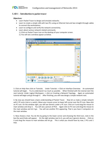
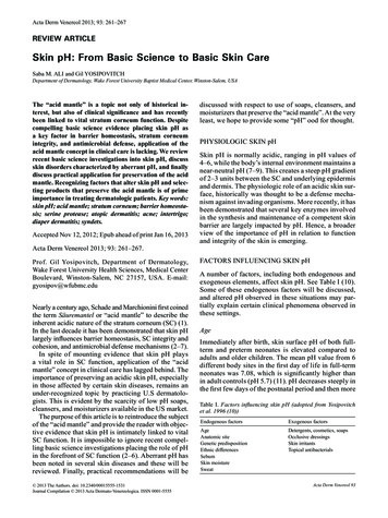
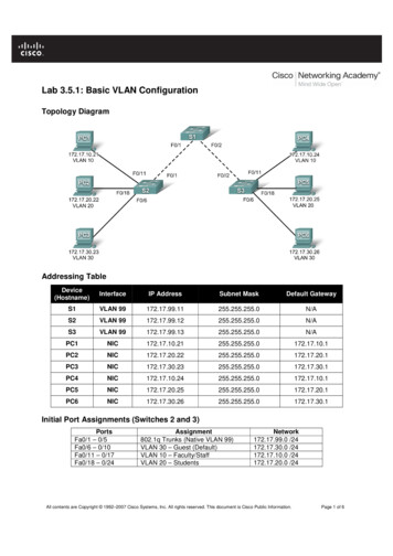
Lab 3.5.1: Basic VLAN ConfigurationTopology DiagramAddressing TableDevice(Hostname)InterfaceIP AddressSubnet MaskDefault GatewayS1VLAN 99172.17.99.11255.255.255.0N/AS2VLAN 99172.17.99.12255.255.255.0N/AS3VLAN 17.30.26255.255.255.0172.17.30.1Initial Port Assignments (Switches 2 and 3)PortsFa0/1 – 0/5Fa0/6 – 0/10Fa0/11 – 0/17Fa0/18 – 0/24Assignment802.1q Trunks (Native VLAN 99)VLAN 30 – Guest (Default)VLAN 10 – Faculty/StaffVLAN 20 – StudentsNetwork172.17.99.0 /24172.17.30.0 /24172.17.10.0 /24172.17.20.0 /24All contents are Copyright 1992–2007 Cisco Systems, Inc. All rights reserved. This document is Cisco Public Information.Page 1 of 6
CCNA ExplorationLAN Switching and Wireless: VLANsLab 3.5.1: Basic VLAN ConfigurationLearning ObjectivesUpon completion of this lab, you will be able to: Cable a network according to the topology diagram Erase the startup configuration and reload a switch to the default state Perform basic configuration tasks on a switch Create VLANs Assign switch ports to a VLAN Add, move, and change ports Verify VLAN configuration Enable trunking on inter-switch connections Verify trunk configuration Save the VLAN configurationTask 1: Prepare the NetworkStep 1: Cable a network that is similar to the one in the topology diagram.You can use any current switch in your lab as long as it has the required interfaces shown in the topology.Note: If you use 2900 or 2950 switches, the outputs may appear different. Also, certain commands maybe different or unavailable.Step 2: Clear any existing configurations on the switches, and initialize all ports in the shutdownstate.If necessary, refer to Lab 2.5.1, Appendix 1, for the procedure to clear switch configurations.It is a good practice to disable any unused ports on the switches by putting them in shutdown. Disable allports on the switches:Switch#config termSwitch(config)#interface range fig-if-range)#interface range gi0/1-2Switch(config-if-range)#shutdownTask 2: Perform Basic Switch ConfigurationsStep 1: Configure the switches according to the following guidelines. Configure the switch hostname. Disable DNS lookup. Configure an EXEC mode password of class. Configure a password of cisco for console connections. Configure a password of cisco for vty connections.Step 2: Re-enable the user ports on S2 and S3.S2(config)#interface range fa0/6, fa0/11, fa0/18S2(config-if-range)#switchport mode accessAll contents are Copyright 1992–2007 Cisco Systems, Inc. All rights reserved. This document is Cisco Public Information.Page 2 of 6
CCNA ExplorationLAN Switching and Wireless: VLANsLab 3.5.1: Basic VLAN ConfigurationS2(config-if-range)#no shutdownS3(config)#interface range fa0/6, fa0/11, fa0/18S3(config-if-range)#switchport mode accessS3(config-if-range)#no shutdownTask 3: Configure and Activate Ethernet InterfacesStep 1: Configure the PCs.You can complete this lab using only two PCs by simply changing the IP addressing for the two PCsspecific to a test you want to conduct. For example, if you want to test connectivity between PC1 andPC2, then configure the IP addresses for those PCs by referring to the addressing table at the beginningof the lab. Alternatively, you can configure all six PCs with the IP addresses and default gateways.Task 4: Configure VLANs on the SwitchStep 1: Create VLANs on switch S1.Use the vlan vlan-id command in global configuration mode to add a VLAN to switch S1. There are fourVLANS configured for this lab: VLAN 10 (faculty/staff); VLAN 20 (students); VLAN 30 (guest); and VLAN99 (management). After you create the VLAN, you will be in vlan configuration mode, where you canassign a name to the VLAN with the name vlan name command.S1(config)#vlan gementStep 2: Verify that the VLANs have been created on S1.Use the show vlan brief command to verify that the VLANs have been created.S1#show vlan briefVLAN NameStatusPorts---- ------------------------------- --------- ----------------------------1defaultactiveFa0/1, Fa0/2, Fa0/4, Fa0/5Fa0/6, Fa0/7, Fa0/8, Fa0/9Fa0/10, Fa0/11, Fa0/12, Fa0/13Fa0/14, Fa0/15, Fa0/16, Fa0/17Fa0/18, Fa0/19, Fa0/20, Fa0/21Fa0/22, Fa0/23, Fa0/24, uestactive99managementactiveAll contents are Copyright 1992–2007 Cisco Systems, Inc. All rights reserved. This document is Cisco Public Information.Page 3 of 6
CCNA ExplorationLAN Switching and Wireless: VLANsLab 3.5.1: Basic VLAN ConfigurationStep 3: Configure and name VLANs on switches S2 and S3.Create and name VLANs 10, 20, 30, and 99 on S2 and S3 using the commands from Step 1. Verify thecorrect configuration with the show vlan brief command.What ports are currently assigned to the four VLANs you have created?Step 4: Assign switch ports to VLANs on S2 and S3.Refer to the port assignment table on page 1. Ports are assigned to VLANs in interface configurationmode, using the switchport access vlan vlan-id command. You can assign each port individually or youcan use the interface range command to simplify this task, as shown here. The commands are shown forS3 only, but you should configure both S2 and S3 similarly. Save your configuration when done.S3(config)#interface range fa0/6-10S3(config-if-range)#switchport access vlan 30S3(config-if-range)#interface range fa0/11-17S3(config-if-range)#switchport access vlan 10S3(config-if-range)#interface range fa0/18-24S3(config-if-range)#switchport access vlan 20S3(config-if-range)#endS3#copy running-config startup-configDestination filename [startup-config]? [enter]Building configuration.[OK]Step 4: Determine which ports have been added.Use the show vlan id vlan-number command on S2 to see which ports are assigned to VLAN 10.Which ports are assigned to VLAN 10?Note: The show vlan id vlan-name displays the same output.You can also view VLAN assignment information using the show interfaces interface switchportcommand.Step 5: Assign the management VLAN.A management VLAN is any VLAN that you configure to access the management capabilities of a switch.VLAN 1 serves as the management VLAN if you did not specifically define another VLAN. You assign themanagement VLAN an IP address and subnet mask. A switch can be managed via HTTP, Telnet, SSH,or SNMP. Because the out-of-the-box configuration of a Cisco switch has VLAN 1 as the default VLAN,VLAN 1 is a bad choice as the management VLAN. You do not want an arbitrary user who is connectingto a switch to default to the management VLAN. Recall that you configured the management VLAN asVLAN 99 earlier in this lab.From interface configuration mode, use the ip address command to assign the management IP addressto the switches.S1(config)#interface vlan 99S1(config-if)#ip address 172.17.99.11 255.255.255.0S1(config-if)#no shutdownS2(config)#interface vlan 99S2(config-if)#ip address 172.17.99.12 255.255.255.0S2(config-if)#no shutdownS3(config)#interface vlan 99S3(config-if)#ip address 172.17.99.13 255.255.255.0All contents are Copyright 1992–2007 Cisco Systems, Inc. All rights reserved. This document is Cisco Public Information.Page 4 of 6
CCNA ExplorationLAN Switching and Wireless: VLANsLab 3.5.1: Basic VLAN ConfigurationS3(config-if)#no shutdownAssigning a management address allows IP communication between the switches, and also allows anyhost connected to a port assigned to VLAN 99 to connect to the switches. Because VLAN 99 isconfigured as the management VLAN, any ports assigned to this VLAN are considered managementports and should be secured to control which devices can connect to these ports.Step 6: Configure trunking and the native VLAN for the trunking ports on all switches.Trunks are connections between the switches that allow the switches to exchange information for allVLANS. By default, a trunk port belongs to all VLANs, as opposed to an access port, which can onlybelong to a single VLAN. If the switch supports both ISL and 802.1Q VLAN encapsulation, the trunksmust specify which method is being used. Because the 2960 switch only supports 802.1Q trunking, it isnot specified in this lab.A native VLAN is assigned to an 802.1Q trunk port. In the topology, the native VLAN is VLAN 99. An802.1Q trunk port supports traffic coming from many VLANs (tagged traffic) as well as traffic that does notcome from a VLAN (untagged traffic). The 802.1Q trunk port places untagged traffic on the native VLAN.Untagged traffic is generated by a computer attached to a switch port that is configured with the nativeVLAN. One of the IEEE 802.1Q specifications for Native VLANs is to maintain backward compatibility withuntagged traffic common to legacy LAN scenarios. For the purposes of this lab, a native VLAN serves asa common identifier on opposing ends of a trunk link. It is a best practice to use a VLAN other than VLAN1 as the native VLAN.Use the interface range command in global configuration mode to simplify configuring trunking.S1(config)#interface range fa0/1-5S1(config-if-range)#switchport mode trunkS1(config-if-range)#switchport trunk native vlan 99S1(config-if-range)#no shutdownS1(config-if-range)#endS2(config)# interface range fa0/1-5S2(config-if-range)#switchport mode trunkS2(config-if-range)#switchport trunk native vlan 99S2(config-if-range)#no shutdownS2(config-if-range)#endS3(config)# interface range fa0/1-5S3(config-if-range)#switchport mode trunkS3(config-if-range)#switchport trunk native vlan 99S3(config-if-range)#no shutdownS3(config-if-range)#endVerify that the trunks have been configured with the show interface trunk command.S1#show interface ngNative vlan9999Vlans allowed on trunk1-40941-4094Vlans allowed and active in management domain1,10,20,30,991,10,20,30,99All contents are Copyright 1992–2007 Cisco Systems, Inc. All rights reserved. This document is Cisco Public Information.Page 5 of 6
CCNA ExplorationLAN Switching and Wireless: VLANsPortFa0/1Fa0/2Lab 3.5.1: Basic VLAN ConfigurationVlans in spanning tree forwarding state and not pruned1,10,20,30,991,10,20,30,99Step 7: Verify that the switches can communicate.From S1, ping the management address on both S2 and S3.S1#ping 172.17.99.12Type escape sequence to abort.Sending 5, 100-byte ICMP Echos to 172.17.99.12, timeout is 2 seconds:!!!!!Success rate is 100 percent (5/5), round-trip min/avg/max 1/2/9 msS1#ping 172.17.99.13Type escape sequence to abort.Sending 5, 100-byte ICMP Echos to 172.17.99.13, timeout is 2 seconds:.!!!!Success rate is 80 percent (4/5), round-trip min/avg/max 1/1/1 msStep 8: Ping several hosts from PC2.Ping from host PC2 to host PC1 (172.17.10.21). Is the ping attempt successful?Ping from host PC2 to the switch VLAN 99 IP address 172.17.99.12. Is the ping attempt successful?Because these hosts are on different subnets and in different VLANs, they cannot communicate without aLayer 3 device to route between the separate subnetworks.Ping from host PC2 to host PC5. Is the ping attempt successful?Because PC2 is in the same VLAN and the same subnet as PC5, the ping is successfulStep 9: Move PC1 into the same VLAN as PC2.The port connected to PC2 (S2 Fa0/18) is assigned to VLAN 20, and the port connected to PC1 (S2Fa0/11) is assigned to VLAN 10. Reassign the S2 Fa0/11 port to VLAN 20. You do not need to firstremove a port from a VLAN to change its VLAN membership. After you reassign a port to a new VLAN,that port is automatically removed from its previous VLAN.S2#configure terminalEnter configuration commands, one per line.S2(config)#interface fastethernet 0/11S2(config-if)#switchport access vlan 20S2(config-if)#endEnd with CNTL/Z.Ping from host PC2 to host PC1. Is the ping attempt successful?Even though the ports used by PC1 and PC2 are in the same VLAN, they are still in differentsubnetworks, so they cannot communicate directly.Step 10: Change the IP address and network on PC1.Change the IP address on PC1 to 172.17.20.22. The subnet mask and default gateway can remain thesame. Once again, ping from host PC2 to host PC1, using the newly assigned IP address.Is the ping attempt successful?Why was this attempt successful?All contents are Copyright 1992–2007 Cisco Systems, Inc. All rights reserved. This document is Cisco Public Information.Page 6 of 6
If necessary, refer to Lab 2.5.1, Appendix 1, for the procedure to clear switch configurations. It is a good practice to disable any unused ports