Transcription
ch01.qxd12/20/027:15 AMPage 1CHAPTER 1Analysis of Stress1.1INTRODUCTIONThe basic structure of matter is characterized by nonuniformity and discontinuityattributable to its various subdivisions: molecules, atoms, and subatomic particles.Our concern in this text is not with the particulate structure, however, and it will beassumed that the matter with which we are concerned is homogeneous andcontinuously distributed over its volume. There is the clear implication in such anapproach that the smallest element cut from the body possesses the same properties as the body. Random fluctuations in the properties of the material are thus ofno consequence. This approach is that of continuum mechanics, in which solid elastic materials are treated as though they are continuous media, rather than composed of discrete molecules. Of the states of matter, we are here concerned onlywith the solid, with its ability to maintain its shape without the need of a containerand to resist continuous shear, tension, and compression.In contrast with rigid-body statics and dynamics, which treat the external behavior of bodies (that is, the equilibrium and motion of bodies without regard tosmall deformations associated with the application of load), the mechanics of solidsis concerned with the relationships of external effect (forces and moments) to internal stresses and strains. Two different approaches used in solid mechanics are themechanics of materials or elementary theory (also called the technical theory) andthe theory of elasticity. The mechanics of materials focuses mainly on the more orless approximate solutions of practical problems. On the other hand, the theory ofelasticity concerns itself largely with more mathematical analysis to determine the“exact” stress and strain distributions in a loaded body. The difference betweenthese approaches is primarily in the nature of the simplifying assumptions used, described in Sec. 3.1.1
ch01.qxd12/20/027:15 AMPage 2External forces acting on a body may be classified as surface forces and bodyforces. A surface force is of the concentrated type when it acts at a point; a surfaceforce may also be distributed uniformly or nonuniformly over a finite area. Bodyforces are associated with the mass of a body, rather than its surfaces, and are distributed throughout the volume of a body. Gravitational, magnetic, and inertiaforces are all body forces. They are specified in terms of force per unit volume. Allforces acting on a body, including the reactive forces caused by supports and bodyforces, are considered to be external forces. Internal forces are the forces that holdtogether the particles forming the body. Unless otherwise stated, we assume in thistext that body forces can be neglected and that forces are applied steadily andslowly. The latter is referred to as static loading.In the International System of Units (SI), force is measured in newtons (N).Because the newton is a small quantity, the kilonewton (kN) is often used in practice. In the U.S. Customary System, force is expressed in pounds (lb) or kilopounds(kips). We shall define all important quantities in both systems of units. However, innumerical examples and problems, SI units will be used throughout the text consistent with international convention. (Table D.2 compares the two systems.)The study of the behavior of members in tension, compression, and bendingbegan with Galileo Galilei (1564–1642), although Robert Hooke (1635–1703) wasthe first to point out that a body is deformed subject to the action of a force. Sincethen many engineers, physicists, and mathematicians in the field of stress analysishave contributed to the basic knowledge on which modern methods are based.*The literature dealing with various aspects of solid mechanics is voluminous. Forthose seeking more thorough treatment, selected references are identified in brackets and compiled at the end of the text.1.2SCOPE OF TREATMENTThe usual objective of mechanics of materials and theory of elasticity is the examination of the load-carrying capacity of a body from three standpoints, strength,stiffness (deformation characteristics), and stability, by using the fundamental principles outlined in Sec. 3.2 and employed throughout the text. These are the laws offorces, the laws of material deformation, and the conditions of geometric compatibility. The principal topics under the general heading of mechanics of solids may besummarized as follows:1. Analysis of the stresses and deformations within a body subject to a prescribedsystem of forces. This is accomplished by solving the governing equations thatdescribe the stress and strain fields (theoretical stress analysis). It is often advantageous, where the shape of the structure or conditions of loading preclude atheoretical solution or where verification is required, to apply the laboratorytechniques of experimental stress analysis.*Historical reviews of mechanics of materials and the theory of elasticity are given inRefs. 1.1 through 1.4.2Chapter 1Analysis of Stress
ch01.qxd12/20/027:15 AMPage 32. Determination by theoretical analysis or by experiment of the limiting values ofload that a structural element can sustain without suffering damage, failure, orcompromise of function.3. Determination of the body shape and selection of the materials that are most efficient for resisting a prescribed system of forces under specified conditions ofoperation such as temperature, humidity, vibration, and ambient pressure. This isthe design function and, more particularly, that of optimum design. Efficiencymay be gauged by such criteria as minimum weight or volume, minimum cost, orany criterion deemed appropriate.The design function, item 3, clearly relies on the performance of the theoreticalanalyses under items 1 and 2, and it is to these that this text is directed. The role ofanalysis in design is observed in examining the following rational procedure in thedesign of a load-carrying member:1. Evaluate the most likely modes of failure of the member. Failure criteria that predict the various modes of failure under anticipated conditions of service are discussed in Chapter 4.2. Determine the expressions relating applied loading to such effects as stress, strain,and deformation. Often, the member under consideration and conditions ofloading are so significant or so amenable to solution as to have been the subjectof prior analysis. For these situations, textbooks, handbooks, journal articles, andtechnical papers are good sources of information. Where the situation is unique,a mathematical derivation specific to the case at hand is required.3. Determine the maximum usable value of stress, strain, or energy. This value is obtained either by reference to compilations of material properties or by experimental means such as simple tension test and is used in connection with therelationship derived in step 2.4. Select a design factor of safety. This is to account for uncertainties in a numberof aspects of the design, including those related to the actual service loads, material properties, or environmental factors. An important area of uncertainty isconnected with the assumptions made in the analysis of stress and deformation.Also, we are not likely to have a secure knowledge of the stresses that may be introduced during machining, assembly, and shipment of the element. The designfactor of safety also reflects the consequences of failure; for example, the possibility that failure will result in loss of human life or injury or in costly repairs ordanger to other components of the overall system. For the aforementioned reasons, the design factor of safety is also sometimes called the factor of ignorance.The uncertainties encountered during the design phase may be of such magnitude as to lead to a design carrying extreme weight, volume, or cost penalties. Itmay then be advantageous to perform thorough tests or more exacting analysis,rather to rely on overly large design factors of safety.The true factor of safety, usually referred to simply as the factor of safety, canonly be determined after the member is constructed and tested. This factor is theratio of the maximum load the member can sustain under severe testing withoutfailure to the maximum load actually carried under normal service conditions,1.2Scope of Treatment3
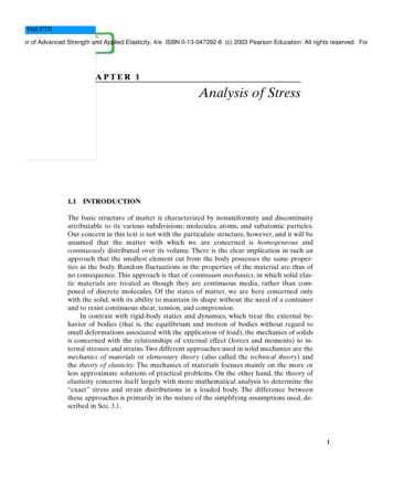
ch01.qxd12/20/027:15 AMPage 4the working load. When a linear relationship exists between the load and thestress produced by the load, the factor of safety n may be expressed asmaximum usable stress(1.1)allowable stressMaximum usable stress represents either the yield stress or the ultimate stress.The allowable stress is the working stress. The factor of safety must be greaterthan 1.0 if failure is to be avoided. Values for factor of safety, selected by the designer on the basis of experience and judgment, are 1.5 or greater. For the majority of applications, appropriate factors of safety are found in variousconstruction and manufacturing codes.n The foregoing procedure is not always conducted in as formal a fashion as maybe implied. In some design procedures, one or more steps may be regarded as unnecessary or obvious on the basis of previous experience.We conclude this section with an appeal for the reader to exercise a degree ofskepticism with regard to the application of formulas for which there is uncertaintyas to the limitations of use or the areas of applicability. The relatively simple formof many formulas usually results from rather severe restrictions in its derivation.These relate to simplified boundary conditions and shapes, limitations on stress andstrain, and the neglect of certain complicating factors. Designers and stress analystsmust be aware of such restrictions lest their work be of no value or, worse lead todangerous inadequacies.In this chapter, we are concerned with the state of stress at a point and thevariation of stress throughout an elastic body. The latter is dealt with in Secs. 1.8 and1.16 and the former in the balance of the chapter.1.3DEFINITION OF STRESSConsider a body in equilibrium subject to a system of external forces, as shown inFig. 1.1a. Under the action of these forces, internal forces will be developed withinthe body. To examine the latter at some interior point Q, we use an imaginary planeto cut the body at a section a–a through Q, dividing the body into two parts. As theFIGURE 1.1. (a) Sectioning of a body; (b) free body with internal forces; (c) enlargedarea A with components of the force F.4Chapter 1Analysis of Stress
ch01.qxd12/20/027:15 AMPage 5forces acting on the entire body are in equilibrium, the forces acting on one partalone must be in equilibrium: This requires the presence of forces on plane a–a.These internal forces, applied to both parts, are distributed continuously over thecut surface. The aforementioned process, referred to as the method of sections, willbe relied on as a first step in solving all problems involving the investigation of internal forces.Figure 1.1b shows the isolated left part of the body. An element of area A, located at point Q on the cut surface is acted on by force F. Let the origin of coordinates be placed at point Q, with x normal and y, z tangent to A. In general, Fdoes not lie along x, y, or z. Decomposing F into components parallel to x, y,and z (Fig. 1.1c), we define the normal stress x and the shearing stresses xy and xz: FxdFx AdA FydFy lim , A : 0 AdA x lim A : 0 xy xz lim A : 0dFz Fz A(1.2)dAThese definitions provide the stress components at a point Q to which the area A is reduced in the limit. Clearly, the expression A : 0 depends on the idealization discussed in the first paragraph of Sec. 1.1. Our consideration is with the average stress on areas, which, while small as compared with the size of the body, islarge compared with interatomic distances in the solid. Stress is thus defined adequately for engineering purposes. As shown in Eq. (1.2), the intensity of force perpendicular, or normal, to the surface is termed the normal stress at a point, while theintensity of force parallel to the surface is the shearing stress at a point.The values obtained in the limiting process of Eq. (1.2) differ from point topoint on the surface as F varies. The stress components depend on not only F,however, but also on the orientation of the plane on which it acts at point Q. Evenat a given point, therefore, the stresses will differ as different planes are considered.The complete description of stress at a point thus requires the specification of thestress on all planes passing through the point.Because the stress ( or ) is obtained by dividing the force by area, it has unitsof force per unit area. In SI units, stress is measured in newtons per square meter1N/m22, or pascals (Pa). As the pascal is a very small quantity, the megapascal(MPa) is commonly used. When U.S. Customary System units are used, stress is expressed in pounds per square inch (psi) or kips per square inch (ksi).1.4COMPONENTS OF STRESS: STRESS TENSORIt is verified in Sec. 1.12 that in order to enable the determination of the stresses onan infinite number of planes passing through a point Q, thus defining the stresses atthat point, we need only specify the stress components on three mutually perpendicular planes passing through the point. These three planes, perpendicular to thecoordinate axes, contain three hidden sides of an infinitesimal cube (Fig. 1.2). Weemphasize that when we move from point Q to point Q¿ the values of stress will, ingeneral, change. Also, body forces can exist. However, these cases will not be dis1.4Components of Stress: Stress Tensor5
ch01.qxd12/20/027:15 AMPage 6FIGURE 1.2. Element subjected to threedimensional stress. All stresseshave positive sense.cussed here (see Sec. 1.8), as we are now merely interested in establishing the terminology necessary to specify a stress component.The general case of a three-dimensional state of stress is shown in Fig. 1.2. Consider the stresses to be identical at points Q and Q¿ and uniformly distributed oneach face, represented by a single vector acting at the center of each face. In accordance with the foregoing, a total of nine scalar stress components defines the stateof stress at a point. The stress components can be assembled in the following matrixform, wherein each row represents the group of stresses acting on a plane passingthrough Q(x, y, z): xx[ ij] C yx zx xy yy zy xz x yz S C yx zz zx xy y zy xz yz S z(1.3)This array represents a tensor of second rank (refer to Sec. 1.12) requiring two indexes to identify its elements or components. A vector is a tensor of first rank; ascalar is of zero rank.The double subscript notation is interpreted as follows: The first subscript indicates the direction of a normal to the plane or face on which the stress componentacts; the second subscript relates to the direction of the stress itself. Repetitive subscripts will be avoided in this text, so the normal stresses xx, yy, and zz will be designated x, y, and z, as indicated in Eq. (1.3). A face or plane is usually identifiedby the axis normal to it; for example, the x faces are perpendicular to the x axis.Sign ConventionReferring again to Fig. 1.2, we observe that both stresses labeled yx tend to twistthe element in a clockwise direction. It would be convenient, therefore, if a signconvention were adopted under which these stresses carried the same sign. Applying a convention relying solely on the coordinate direction of the stresses wouldclearly not produce the desired result, inasmuch as the yx stress acting on theupper surface is directed in the positive x direction, while yx acting on the lowersurface is directed in the negative x direction. The following sign convention, whichapplies to both normal and shear stresses, is related to the deformational influence6Chapter 1Analysis of Stress
ch01.qxd12/20/027:15 AMPage 7of a stress and is based on the relationship between the direction of an outwardnormal drawn to a particular surface and the directions of the stress components onthe same surface.When both the outer normal and the stress component face in a positive direction relative to the coordinate axes, the stress is positive. When both the outer normal and the stress component face in a negative direction relative to the coordinateaxes, the stress is positive. When the normal points in a positive direction while thestress points in a negative direction (or vice versa), the stress is negative. In accordance with this sign convention, tensile stresses are always positive and compressive stresses always negative. Figure 1.2 depicts a system of positive normal andshear stresses.Equality of Shearing StressesWe now examine properties of shearing stress by studying the equilibrium of forcesacting on the cubic element shown in Fig. 1.2. As the stresses acting on oppositefaces (which are of equal area) are equal in magnitude, but opposite in direction,translational equilibrium in all directions is assured; that is, Fx 0, Fy 0, and Fz 0. Rotational equilibrium is established by taking moments of the x-, y-, andz-directed forces about point Q, for example. From Mz 0,1- xy dy dz2dx 1 yx dx dz2dy 0Simplifying, xy yx(1.4a)Likewise, from My 0 and Mx 0, we have xz zx, yz zy(1.4b,c)Hence, the subscripts for the shearing stresses are commutative, and the stress tensor is symmetric. This means that shearing stresses on mutually perpendicular planesof the element are equal. Therefore, no distinction will hereafter be made betweenthe stress components xy and yx, xz and zx, or yz and zy. In Sec. 1.8, it is shownrigorously that the foregoing is valid even when stress components vary from onepoint to another.Indicial NotationMany equations of elasticity become unwieldy when written in full, unabbreviatedform; see, for example, Eq. (1.24). As the complexity of the situation described increases, so does that of the formulations, tending to obscure the fundamentals in amass of symbols. For this reason, the more compact indicial notation or tensor notation described in Appendix A is sometimes found in technical publications. A stresstensor is written in indicial notation as ij, where i and j each assume the values x, y,and z as required by Eq. (1.3). Generally, such notation is not employed in this text.1.4Components of Stress: Stress Tensor7
ch01.qxd12/20/027:15 AM1.5Page 8SOME SPECIAL CASES OF STRESSUnder particular circumstances, the general state of stress (Fig. 1.2) reduces to simpler stress states as briefly described here. These stresses, which are commonly encountered in practice, will be given detailed consideration throughout the text.a. Triaxial Stress. We shall observe in Sec. 1.13 that an element subjected to onlystresses 1, 2, and 3 acting in mutually perpendicular directions is said to be ina state of triaxial stress. Such a state of stress can be written as 1C000 2000S 3(a)The absence of shearing stresses indicates that the preceding stresses are theprincipal stresses for the element.A special case of triaxial stress, known as sphericalor dilatational stress, occurs if all principal stresses are equal (see Sec. 1.14). Equaltriaxial tension is sometimes called hydrostatic tension. An example of equal triaxial compression is found in a small element of liquid under static pressure.b. Two-dimensional or Plane Stress. In this case, only the x and y faces of the element are subjected to stress, and all the stresses act parallel to the x and y axes asshown in Fig. 1.3a. The plane stress matrix is writtenB x xy xyR y(1.5)Although the three-dimensional nature of the element under stress should notbe forgotten, for the sake of convenience we usually draw only a two-dimensionalview of the plane stress element (Fig. 1.3b). When only two normal stresses arepresent, the state of stress is called biaxial. These stresses occur in thin platesstressed in two mutually perpendicular directions.c. Pure Shear. In this case, the element is subjected to plane shearing stresses only,for example, xy and yx (Fig. 1.3c). Typical pure shear occurs over the cross sections and on longitudinal planes of a circular shaft subjected to torsion.d. Uniaxial Stress. When normal stresses act along one direction only, the onedimensional state of stress is referred to as a uniaxial tension or compression.FIGURE 1.3. (a) Element in plane stress; (b) two-dimensional presentation of planestress; (c) element in pure shear.8Chapter 1Analysis of Stress
ch01.qxd12/20/021.67:15 AMPage 9INTERNAL FORCE-RESULTANT AND STRESS RELATIONSDistributed forces within a member can be represented by a statically equivalentsystem consisting of a force and a moment vector acting at any arbitrary point (usually the centroid) of a section. These internal force resultants, also called stress resultants, exposed by an imaginary cutting plane containing the point through themember, are usually resolved into components normal and tangent to the cut section (Fig. 1.4). The sense of moments follows the right-hand screw rule, often represented by double-headed vectors, as shown in the figure. Each component can beassociated with one of four modes of force transmission:1. The axial force P or N tends to lengthen or shorten the member.2. The shear forces Vy and Vz tend to shear one part of the member relative to theadjacent part and are often designated by the letter V.3. The torque or twisting moment T is responsible for twisting the member.4. The bending moments My and Mz cause the member to bend and are often identified by the letter M.A member may be subject to any or all of the modes simultaneously. Note that thesame sign convention is used for the force and moment components that is used forstress; a positive force (or moment) component acts on the positive face in the positive coordinate direction or on a negative face in the negative coordinate direction.A typical infinitesimal area dA of the cut section shown in Fig. 1.4 is acted onby the components of an arbitrarily directed force dF, expressed using Eqs. (1.2) asdFx x dA, dFy xy dA, and dFz xz dA. Clearly, the stress components onthe cut section cause the internal force resultants on that section. Thus, the incremental forces are summed in the x, y, and z directions to giveP L x dA,Vy L xy dA,Vz L xz dA(1.6a)In a like manner, the sums of the moments of the same forces about the x, y, and zaxes lead toT L1 xzy - xyz2 dA,My L x z dA,Mz -L xy dA(1.6b)FIGURE 1.4. Positive forces and moments on a cutsection of a body and components ofthe force dF on an infinitesimal areadA.1.6Internal Force-Resultant and Stress Relations9
ch01.qxd12/20/027:15 AMPage 10FIGURE 1.5. Prismatic bar in tension.where the integrations proceed over area A of the cut section. Equations (1.6) represent the relations between the internal-force resultants and the stresses. In the nextparagraph we illustrate the fundamental concept of stress and observe how Eqs.(1.6) connect internal force resultants and the state of stress in a specific case.Consider a homogeneous prismatic bar loaded by axial forces P at the ends(Fig. 1.5a). A prismatic bar is a straight member having constant cross-sectionalarea throughout its length. To obtain an expression for the normal stress, we makean imaginary cut (section a–a) through the member at right angles to its axis. Afree-body diagram of the isolated part is shown in Fig. 1.5b, wherein the stress issubstituted on the cut section as a replacement for the effect of the removed part.Equilibrium of axial forces requires that P 1 x dA or P A x. The normalstress is therefore x PA(1.7)where A is the cross-sectional area of the bar. Because Vy, Vz, and T all are equal tozero, the second and third of Eqs. (1.6a) and the first of Eqs. (1.6b) are satisfied by xy xz 0. Also, My Mz 0 in Eqs. (1.6b) requires only that x be symmetrically distributed about the y and z axes, as depicted in Fig. 1.5b. When the memberis being extended as in the figure, the resulting stress is a uniaxial tensile stress; if thedirection of forces were reversed, the bar would be in compression under uniaxialcompressive stress. In the latter case, Eq. (1.7) is applicable only to chunky or shortmembers owing to other effects that take place in longer members.*Similarly, application of Eqs. (1.6) to torsion members, beams, plates, and shellswill be presented as the subject unfolds, following the derivation of stress–strain relations and examination of the geometric behavior of a particular member. Applying the method of mechanics of materials, we shall develop other elementaryformulas for stress and deformation. These, also called the basic formulas of mechanics of materials, are often used and extended for application to more complexproblems in advanced mechanics of materials and the theory of elasticity. For reference purposes to preliminary discussions, Table 1.1 lists some commonly encoun*Further discussion of uniaxial compression stress is found in Sec. 11.5, where we takeup the classification of columns.10Chapter 1Analysis of Stress
ch01.qxd12/20/027:15 AMTABLE 1.1.Page 11Commonly Used Elementary Formulas for Stress a1. Prismatic Bars of Linearly Elastic Material x Axial loading: Torsion:Bending:Shear:where x normal axial stress shearing stress due to torque xy shearing stress due to verticalshear forceP axial forceT torqueV vertical shear forceM bending moment about z axisA cross-sectional areay, z centroidal principal axesof the areaT ,J x - xy PA(a) max My,ITrJ max (b)Mc(c)IVQIb(d)I moment of inertia aboutneutral axis (N.A.)J polar moment of inertiaof circular cross sectionb width of bar at which xyis calculatedr radiusQ first moment about N.A. of thearea beyond the point at which xy is calculated2. Thin-Walled Pressure VesselsCylinder:Sphere:where tangential stress in cylinder wall a axial stress in cylinder wall membrane stress in sphere wall pr,t a pr2tpr2t(e)(f)p internal pressuret wall thicknessr mean radiusaDetailed derivations and limitations of the use of these formulas are discussed in Secs. 1.6, 5.7, 6.2, and 13.13.1.7Stresses on Inclined Planes in an Axially Loaded Member11
ch01.qxd12/20/027:15 AMPage 12tered cases. Each equation presented in the table describes a state of stress associated with a single force, torque, moment component, or pressure at a section of atypical homogeneous and elastic structural member. When a member is acted on simultaneously by two or more load types, causing various internal-force resultantson a section, it is assumed that each load produces the stress as if it were the onlyload acting on the member. The final or combined stress is then determined by superposition of the several states of stress, as discussed in Sec. 2.2.The mechanics of materials theory is based on the simplifying assumptions related to the pattern of deformation so that the strain distributions for a cross section of the member can be determined. It is a basic assumption that plane sectionsbefore loading remain plane after loading. The assumption can be shown to be exactfor axially loaded prismatic bars, for prismatic circular torsion members, and forprismatic beams subjected to pure bending. The assumption is approximate forother beam situations. However, it is emphasized that there is an extraordinarilylarge variety of cases in which applications of the basic formulas of mechanics ofmaterials lead to useful results. In this text we hope to provide greater insight intothe meaning and limitations of stress analysis by solving problems using both theelementary and exact methods of analysis.1.7STRESSES ON INCLINED PLANES IN AN AXIALLYLOADED MEMBERWe now consider the stresses on an inclined plane b–b of the bar in uniaxial tensionshown in Fig. 1.5a, where the normal x¿ to the plane forms an angle with the axialdirection. On an isolated part of the bar to the left of section b–b, the resultant Pmay be resolved into two components: the normal force Px¿ P cos and theshear force Py¿ -P sin , as indicated in Fig. 1.6a. Thus, the normal and shearingstresses, uniformly distributed over the area A x¿ A/cos of the inclined plane(Fig. 1.6b), are given by x¿ P cos x cos2 A x¿ x¿y¿ -(1.8a)P sin - x sin cos A x¿(1.8b)The negative sign in Eq. (1.8b) agrees with the sign convention for shearing stressesdescribed in Sec. 1.4. The foregoing process of determining the stress in proceedingfrom one set of coordinate axes to another is called stress transformation.Equations (1.8) indicate how the stresses vary as the inclined plane is cut atvarious angles. As expected, x¿ is a maximum 1 max2 when is 0 or 180 , and x¿y¿is maximum 1 max2 when is 45 or 135 . Also, max ; 12 max. The maximumstresses are thus max x,12 max ; 12 x(1.9)Chapter 1Analysis of Stress
ch01.qxd12/20/027:15 AMPage 13FIGURE 1.6. Isolated part of the bar shown in Fig. 1.5.Observe that the normal stress is either maximum or a minimum on planes forwhich the shearing stress is zero.Figure 1.7 shows the manner in which the stresses vary as the section is cut atangles varying from 0 to 180 . Clearly, when 7 90 , the sign of x¿y¿ in Eq.(1.8b) changes; the shearing stress changes sense. However, the magnitude of theshearing stress for any angle determined from Eq. (1.8b) is equal to that for 90 . This agrees with the general conclusion reached in the preceding section:Shearing stresses on mutually perpendicular planes must be equal.We note that Eqs. (1.8) can also be used for uniaxial compression by assigningto P a negative value. The sense of each stress direction is then reversed in Fig. 1.6b.EXAMPLE 1.1Compute the stresses on the inclined plane with 35 for a prismaticbar of a cross-sectional area 800 mm2, subjected to a tensile load of60 kN (Fig. 1.5a). Then
Consider a body in equilibrium subject to a system of external forces, as shown in Fig. 1.1a. Under the action of these forces, internal forces will be developed within the body.To examine the latter at some interior point . Q, we use an imaginary plane to cut the body at a section . a–a. through . Q, div