Transcription
TM 9-4910-586-14&PTECHNICAL ST)FORSTAND, TRANSPORT, ENGINE(NSN 4910-00-338-6673)H E A D Q U A R T E R S ,D E P A R T M E N TO FT H EA R M YDECEMBER 1979
TM 9-4910-586-14&PT ECHNICAL M ANUALNo. 9-4910-586-14&P}HEADQUARTERSDEPARTMENT OF THE ARMYWASHINGTON, DC, 31 December 1979OPERATOR, ORGANIZATIONAL, DIRECT SUPPORT AND GENERAL SUPPORTMAINTENANCE MANUAL(INCLUDING REPAIR PARTS LIST)FORSTAND, TRANSPORT, ENGINE(NSN 4910-00-338-6673)REPORTING ERRORS AND RECOMMENDING IMPROVEMENTSYou can help improve this manual. If you find any mistakes or if you know ofa way to improve the procedures, please let us know. Mail your letter, DA Form2028 (Recommended Changes to Publications and Blank Forms), or DA Form2028-2, located in the back of this manual direct to: Commander, US ArmyArmament Materiel Readiness Command, ATTN: DRSAR-MAS, Rock Island,IL 61299. A reply will be furnished directly to you.NOTEThis manual is published for the purpose of identifying an authorized commercial manual for the useof the personnel to whom this stand is issued.Manufactured by: KHC Industries, Inc.41 Deming RoadBerlin, CT 06037Procured under Contract No. DAAA09-76-C-6675This technical manual is an authentication of the manufacturer’s commercialliterature and does not conform with the format and content specified in AR310-3, Military Publications. This technical manual does, however, containavailable information that is essential to the operation and maintenance of theequipment.i
TABLE OF CONTENTSPageSectionIIIIIIINTRODUCTION AND DESCRIPTION . . . . . . . . . . . . . . . . . .11-1.1-3.1-5.1-7.1-9.11111OPERATION . . . . . . . . . . . . . . . . . . . . . . . . . . . . . . .22-1.2-3.2-5.General . . . . . . . . . . . . . . . . . . . . . . . . . . . . .Preparation For Use . . . . . . . . . . . . . . . . . . . . . .Operation Procedures . . . . . . . . . . . . . . . . . . . . . .222MAINTENANCE INSTRUCTIONS . . . . . . . . . . . . . . . . . . . .3.333334444. . . . . . . . .44PARTS LIST. . . . . . . . . . . . . . . . . . . . . . . . . . . . . . .54-1.4-3.553-16.ii. . . . . . . . . . neral . . . . . . .Purpose . . . . . . .Description . . . . .Stand Base AssemblySupport Assemblies .General . . . . . . . . . . . . . . . . . . . . . . . .Cleaning and Lubrication. . . . . . . . . . . . . . .Inspection . . . . . . . . . . . . . . . . . . . . . . .Repair . . . . . . . . . . . . . . . . . . . . . . . . .Rust Removal and Repainting . . . . . . . . . . . . .Disassembly. . . . . . . . . . . . . . . . . . . . . .Removal of Support Assemblies. . . . . . . . . . . .Removal of Wheel Assemblies. . . . . . . . . . . . .Removal of Jack Stand. . . . . . . . . . . . . . . . .Removal of Rear Brace (Left andRight Legs) . . . . . . . . . . . . . . . . . . . . .Assembly. . . . . . . . . . . . . . . . . . . . . . . . . . . . . . . . .General . . . . . . . . . . . . . . . . . . . . . . . . . . . . .Parts List. . . . . . . . . . . . . . . . . . . . . . . . . . . .
TM 9-4910-586-14 & PSECTION IINTRODUCTION AND DESCRIPTION1-1. GENERAL1-2. This manual provides operation, maintenance, and parts listing information for theDepartment of the Army,Drawing Number 8708857 UniversalTransport Stand.1-3. PURPOSE1-4. The Universal Transport Stand, herein referred as Stand, is provided for moving ofengines and heavy equipment. Adjustable supports provide a rigid mounting for various sizeequipment . In addition to providing a means of moving equipment, the Stand may be utilizedto provide storage of equipment to enable quick access when required.1-5. DESCRIPTION1-6. The Stand is a general purpose, heavy-duty, engine transport stand of welded steelconstruction. The Stand is composed of a base assembly mounted on wheels and fourvertically-mounted support assemblies.1-7. Stand Base Assembly1-8. The Stand base assembly is composed of a welded, steel channel frame with attachedwheel assemblies, jack stand, and rear brace assembly. The front of the Stand utilizesswivel wheel assemblies, while the rear of the Stand utilizes fixed wheel assemblies. Anadjustable jack stand is provided at the left front of the Stand base assembly to lock theStand in position, and to avoid rolling on inclines. The rear brace assembly, provided as anadditional means of support for engine mounting, is bolted through slotted holes in the rearcross-member of the Stand base assembly to enable lateral adjustment.1-9. Support Assemblies1-10. The support assemblies, which are vertically mounted and adjustable, are the mainload-bearing supports of the Stand. The support assemblies are bolted to the Stand baseassembly through slotted holes in the support assemblies and the Stand base assembly. Slotsaxes are 90 degrees apart, enabling a wide range of lateral and longitudinal adjustment tosuit various equipment dimensions. Lateral adjustment provides for dimensions of 9 to 39inches (nominal) width. Longitudinal adjustment provides for dimensions of 7-3/8 to 31-5/8inches (nominal) between support assembly centerlines.1
TM 9-4910-586-14 & PSECTION IIOPERATION2-1. GENERAL2-2. The Stands are shipped banded together on an approximate 42 x 48 inch pallet. Therear brace assembly (right and left legs), the support assemblies, and hardware for eachStand is packaged in a cardboard box positioned and banded in the center of the pallet.One box is supplied with each stand. Preparation for use and operation procedure follow.2-3.PREPARATION FOR USE2-4. The following procedures provide unpacking and set-up instructions for the Stand.(See figure 1.)1. Remove the steel bands securing the Stand(s) to the pallet.2. Remove the Stand(s) from the pallet.3. Remove the steel bands attaching the cardboard box(es) to the pallet.4. Remove the cardboard box(es) from the center of the pallet.5.Remove the support assemblies, rear brace assembly (right and left legs), andhardware from each cardboard box.6. Attach four support assemblies (item 10) to the Stand base assembly with screw(item 11), nut (item 14) and washers (items 12 & 13).7. Loosely attach rear brace assembly left leg (item 19) to left end of the rear crossmember with screw (item 7), washers (items 17 & 18), and nut (item 9).8. Loosely attach rear brace assembly right leg (item 19) to right end of rear crossmember with screw (item 21), spacer (item 22), washers (items 17 & 18), andnut (item 9).NOTESpacer (item 22) is inserted between right legand rear crossmember.9. Securely attach right and left legs together with screw (item 7), washer (item 17),and nut (item 9).10. Secure mounting bolts on lower end of left and right legs at rear crossmember.2-5.OPERATIONPROCEDURES2-6. Operation procedures for use of the Stand are as follows:1.Position the Stand as required near the equipment to be moved.2. Tighten the jack stand at the left front of the Stand to insure that the Stand is steady.3. Adjust the vertical support assemblies and rear brace assembly as required toaccommodate the dimensions of the load.2
TM 9-4910-586-14 & P4. Using a suitable lifting device, lift the equipment to be moved into position over theStand and lower the equipment into position.5. Insure that the equipment is secure in the Stand prior to proceeding.6. Loosen the jack stand at the left front of the Stand.7. Move the equipment mounted on the Stand to the desired location.8. Tighten the jack stand at the left front of the Stand.9. Using a suitable lifting device, lift the equipment from the Stand.SECTION IIIMAINTENANCE INSTRUCTIONS3-1. GENERAL3-2. Maintenance is limited to general cleaning, lubrication, and replacement of damagedparts.3-3. CLEANING AND LUBRICATION3-4. Periodically, the Stand should be wiped clean of grease and dirt. The wheel assembliesshould be greased with general-purpose grease (MIL-G-23549 or equivalent). Note that eachwheel assembly has a grease fitting on the wheel axle and, in addition, each swivel wheelassembly has a grease fitting on the swivel axis.3-5.INSPECTION3-6. The Stand should be inspected periodically for damaged parts, faulty or loosely-mountedwheel assemblies, and rust build-up. Inspect wheel assemblies for binding, chipped wheelsand defective bearings. Refer to paragraph 3-7 for repair procedures.3-7. REPAIR3-8. Repair procedures are limited to rust removal and repainting and replacement ofdamaged parts. Faulty wheel assemblies and damaged parts should be replaced (refer toparagraph 3-10 for disassembly procedures).3-9. Rust Removal and Repainting1. Remove the affected part (refer to paragraph 3-10 for disassembly procedures).2. Remove all rust from the area with sandpaper.3. Apply military approved primer to the area.4. Allow primer to dry thoroughly.5. Apply military approved matching paint.6. Allow the paint to dry thoroughly.3
TM 9-4910-586-14 & P7. Reattach the part to the Stand (refer to paragraph 3-17 for assembly procedures).3-10.DISASSEMBLY3-11. The following procedures detail disassembly of the Stand. Retain all attaching hardware for reassembly. Refer to figure 1 for parts location.3-12. Removal of Support Assemblies1. Remove attaching screw, nut, and washers from base of the support assembly(item 10).2. Lift support assembly from Stand base assembly.3-13. Removal of Wheel Assemblies1. Remove four attaching screws, nuts, and washers from each Stand base assemblymounting plate (item 16).2. Remove each wheel assembly (items 6 & 15) and wheel assembly mounting plate(item 3A).3-14. Removal of Jack Stand1.Loosen setscrew (item 5) and remove foot (item 4).2.Using suitable wrench, unthread locking screw (item 2) by turning counterclockwise.3. Remove locking screw.3-15.Removal of Rear Brace (Left and Right Legs)1.Remove attaching screw, washer, and nut securing left and right legs (item 19).2. Remove attaching screw, washer, and nut securing left leg and remove left leg.3.3-16.Remove attaching screw, washer, spacer, and nut securing right leg and removeright leg.ASSEMBLY3-17. For assembly, reverse the disassembly procedures of paragraph 3-10 and tightenattaching screws securely.4
TM 9-4910-586-14 & PSECTION IVPARTS LIST4-1. GENERAL4-2. This section provides a listing of part numbers and a description for all parts andassemblies of the Stand.4-3. PARTS LIST4-4. All parts are referenced to figure 1. Unless otherwise noted, part numbers listedhave been assigned by the Rock Island Arsenal. The code number of the Rock Island Arsenalis listed in the description column, in addition to drawing number.5
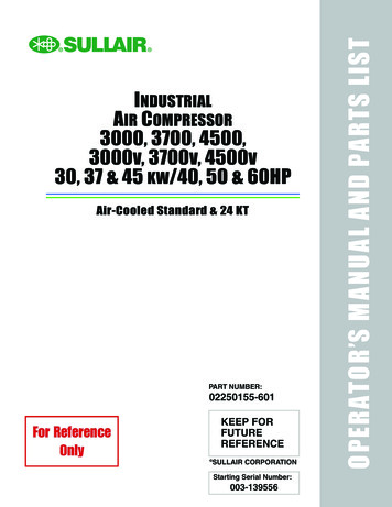
TM 9-4910-586-14 & PFigure 1.6Universal Transport Stand
TM9-4910-586-14 & 3-18NAS 67/8(BLANK)DESCRIPTIONCROSSMEMBER, FRONT; MFR. 19204DWG. C8708860SCREW, LOCKING; MFR. 19204,DWG. B7750159PLATE; MFR. 19204, DWG. A8708871FOOT; MFR. 19204, DWG. A8708870SETSCREWWHEEL ASSEMBLY, FRONT SWIVEL; MFR. 07393SCREWWASHERNUTSUPPORT ASSEMBLY; MFR. 19204,DWG. C8708862SCREWWASHERWASHERNUTWHEEL ASSEMBLY, REAR; MFG. 07393PLATE; MFR. 19204, DWG. B7550160WASHERWASHER, BEVELLEG; MFR. 19204, DWG. B8708865CROSSMEMBER, REAR; MFR. 19204,DWG. C8708861SCREWSPACER; MFR. 19204, DWG. A8708858CHANNEL, SIDE; MFR. 19204, DWG. C8708866QTY.11111218161944444244221112
TM 9-4910-586-14&PINSTRUCTIONS FOR REQUISITIONING PARTSNOTIDENTIFIED BY NSNWhen requisitioning parts not identified by National Stock Number, it ismandatory that the following information be furnished the supply officer.3N0911-Manufacturer's Federal Supply Code Number -2-Manufacturer’s Part Number exactly as listed herein.3-Nomenclature exactly as listed herein, including dimensions, ifnecessary.4-Manufacturer’s Model Number - Model5-Manufacturer’s Serial Number (End Item)6-Any other information such as Type, Frame Number, and ElectricalCharacteristics, if applicable.7-If DD Form 1348 is used, fill in all blocks except 4, 5, 6, andRemarks field in accordance with AR 725-50.Complete Form as Follows:(a) In blocks 4, 5, 6, list manufacturer’s Federal Supply Code Number3N091followed by a colon and manufacturer’sPart Number for the repair part.(b) Complete Remarks field as follows:(nomenclature of repair part)Noun:4910-00-338-6673NSN:For:Manufacturer:KHC Industries, Inc.Model:Serial:(of end item)Any other pertinent information such as Frame Number,Type, Dimensions, etc.9
By Order of the Secretary of the Army:E. C. MEYEROfficial:J. C. PENNINGTONMajor General, United States ArmyThe Adjutant GeneralGeneral, United States ArmyChief of Staff
TM 9-4910-586-14&PSTAND, TRANSPORT, ENGINE - 1979
This fine document.Was brought to you by me:Liberated Manuals -- free army and government manualsWhy do I do it? I am tired of sleazy CD-ROM sellers, who take publiclyavailable information, slap “watermarks” and other junk on it, and sell it.Those masters of search engine manipulation make sure that their sites thatsell free information, come up first in search engines. They did not create it.They did not even scan it. Why should they get your money? Why are notletting you give those free manuals to your friends?I am setting this document FREE. This document was made by the USGovernment and is NOT protected by Copyright. Feel free to share,republish, sell and so on.I am not asking you for donations, fees or handouts. If you can, pleaseprovide a link to liberatedmanuals.com, so that free manuals come up first insearch engines: A HREF http://www.liberatedmanuals.com/ Free Military and Government Manuals /A – SincerelyIgor Chudovhttp://igor.chudov.com/– Chicago Machinery Movers
2-2. The Stands are shipped banded together on an approximate 42 x 48 inch pallet. The rear brace assembly (right and left legs), the support assemblies, and hardware for each Stand is packaged in a cardboard box positioned and banded in the center of the pallet. One box is supplied with e