Transcription
USER MAUNAL12345EW20General Description. 1System Specification & Function . 22.1 Basic Specification . 22.2 System Specifications . 22.3 Electrical & Other Specifications . 32.4 System Features List. 4Preparation & Note for the System Installation . 53.1 Preparation for System Installation . 53.2 Special Requirements for Installation Environment . 53.3 Equipment Remarks . 5EW20 PCB & Cabinet Layout . 64.1 Three-View Drawing Of EW20 . 64.2 EW20 Mother Board Unit (E8MBUA). 74.3 EW20 Expansion Unit (E8EPUA) . 8System Program Setting. 95.1 System Program Command . 95.2 System Reset . 95.35.45.55.65.75.85.95.10CO line Connection Setting . 9Answer Mode for CO Line Incoming . 9Record/Play of the Voice Announcement. 10Ringing Extension Assignment . 111st Operator Extension Setting . 112nd Operator Extension Setting . 11Extension COS (Class of Service) Assignment . 11Extension No. Length Setting . 125.11 Extension Number Setting . 125.12 System Password Changing . 135.13 CO Line Hunting Code Setting . 135.145.155.165.175.185.19Availability of Ext. to Access CO Line . 13Prohibited Code Setting . 13Special Local Call No. Setting . 13Forced Account Setting . 141st Landline Prefixed Number Setting . 142nd Landline Prefixed Number Setting . 145.205.215.225.235.24Flash Time Setting . 15To switch between Internal/External Music . 15Fax Extension Setting . 15Door Phone Setting . 15Transfer Indication Tone Selecting for DISA Calls . 16Aristel GroupCONTENT
EW206USER MAUNAL5.255.265.275.285.295.305.315.32System On-Hold Music Selecting . 16Auto Attendant Response Time Setting . 16DISA No Dialing Processing Mode. 17Manager and Secretary Pair Setting . 17Emergency Call Setting . 17Multiple CO Hunting Code Setting . 18Hot Line Setting . 18Reserved . 185.335.345.355.365.37Speed Dialing Setting . 18Reserved . 19Enable/Disable 1st Landline Prefixed Number. 19Reserved . 19Clear the Extension No. . 195.38 Extension Group Setting . 195.39 Remote Programming . 20SLT Extension Operation. 206.1 Make an Intercom Call . 206.1.1 Common Intercom Call . 206.1.2 Call The Operator Extension . 206.1.3 Intercom Callback . 206.1.4 Call the Extension Group . 216.2 Make An External Call . 216.2.1 CO Line Hunting . 216.2.2 Hot CO Line . 216.2.3 Trunk Queuing Callback . 226.2.4 Last Number Redialing . 226.2.5 CO Line Flash . 226.3 Call Transfer / Pickup / Forward/Call Hold / Retrieve the Held Call. 226.3.1 Call Transfer . 236.3.2 Call Pickup . 236.3.2.1 Directed Call Pickup . 236.3.2.2 General Call Pickup. 236.3.3 Call Hold / Retrieve the Held Call . 246.3.4 Call Forward / Do-Not-Disturb . d All Call . 24Forward The Call When Busy . 24Forward The Call When No Answer . 24Intercom Call Forward to External Number . 25Do-Not-Disturb . 25Aristel Group
USER MAUNALEW206.4Inquiry . 266.4.1 Extension Port No. & Extension No. Inquiring . 266.4.2 System Software Version Inquiring . 266.5 Forced Account Code . 266.5.1 Use Individual Account . 266.5.2 Individual Account Password Changing . 266.6 Three-Way Conference . 276.7 Call Split. 27Appendix: Settings & Operation . 28Aristel GroupCONTENT
USER MAUNAL1EW20General DescriptionThanks for choosing our Aristel EW20 telephone switching system.Derived from Aristel AV-20 telephone system, EW20 is specially designed as a concise andpractical version for most users. Inheriting the characters of spatiality and reliability, EW20 ismost suitable for small office and home office with its rich practical functions. The maindifference between the EW20 and AV-20 is that, EW20 can only connect with Single LineTelephone while AV-20 can connect with both Single Line Telephone and Key telephone.The basic capacity of EW20 is 2 CO lines and 8 Single Line stations, and can be expanded to amaximum of 4 CO lines and 16 Single Line stations. This User manual gives clear descriptionsof all the steps for installation and operation. If you have any queries, please contact yourauthorized agent for help.Aristel Group1
EW202USER MAUNALSystem Specification & Function2.1Basic Specification System Capacity:208 416 Built-in Voice Auto Attendant CO/station lines connected by RJ-112.2System SpecificationsAristel EW20Basic CapacityExpansion CapacityMaximum CapacityCO Line224Single Line Station8816111224单机Built-in AutoAttendantPower Failure TransferPhone (PFT)Table 1: System Specifications2Aristel Group
EW20USER MAUNAL2.3Electrical & Other SpecificationsEW SeriesEW20Input AC VoltageAC220V( 15﹪)50HzPower AdapterOutput AC VoltagePower Consumption25V 1A &System75V 0.02A 20WDialingOutgoing DialingToneSignalIntercom DialingToneWiring InstallationCO Line2 wiresSLT0.85WSLT2 wiresSystem Dimension(mm)306 205 70mmWorking Temperature-10 40 Working Humidity 85%(non-condensing)Switch ModeSDM(Space Division Matrix)Table 2: System Electric specifications Subject to the changes without notice.Aristel Group3
EW202.4USER MAUNALSystem Features ListSpecial features: Flexible Extension Numbering with 2 to 4 digits length and the first digit is 1 - 8 at option. The Caller ID number will be displayed no matter from the incoming lines or intercom. Thisnumber also can be forwarded to other extension. Up to 16 ringing extensions for the incoming calls can be assigned and display CID number. Power Failure Transfer Phone (PFT): 4 Lines. Built-in Auto Attendant function for greeting message up to 40 seconds. Built-in PBX trunk line access code while EW20 connected behind external PBX. Provides 40 groups Force Account Code in total for Toll call management. Multi-level Toll Restriction programmable: Internal calls, Local calls, Long Distance calls andInternational calls. Provides 20 sets programmable restricted code for outgoing calls. Self-checking of port number and extension number to facilitate the installation. EEPROM Memory Design to ensure the programming can be saved even power failed.Other features: Call Pickup Call transfer Call forward DND Setting Hot Line setting Speed Dialing4Aristel Group
EW20USER MAUNAL33.1Preparation & Note for the System InstallationPreparation for System Installation Please check whether the system capacity and the quantity of phones are suitable or not. Please prepare the necessary wires and instruments for installation. Please carefully read this manual before installation and follow up the procedures ofinstallation on this manual.3.2Special Requirements for Installation Environment Input AC Voltage: AC220V 15%。 Wiring Requirements:CO Line: 2-conductor wiringSLT Extension: 2-conductor wiringExternal Music Source: 2-conductor wiring。3.3Equipment Remarks The system should be installed at a clean, dry and secure position, 10 centimeters abovethe ground to avoid the vibration. The location must have adequate ventilation and a temperature range between-10 40 with a 85% non-condensing relative humidity. The installation site should have sufficient room to mount the System along with thenecessary connecting blocks and ancillary equipment. The installation site should not be atthe area with static electricity (e.g. Dry copiers), or vibration (e.g. Heavy duty machinery).。 This system must use the independent power input. The power should better not sharewith other power-consumption equipment, for example: huge power-consumption machineand be controlled directly by main switch. In addition, the location must be far away fromhigh frequency & noise soundings to avoid the interference from radiation 『EMI』. Voltage Stabilizer is recommended if the electricity supply is not so stable. Please use the lightening-protection equipment to guarantee system’s stability. Suggest using twist wires for CO line & station line to avoid noise and interruption. SLT wiring must be away from some other disturbance (e.g.:radio wave).Otherwise aseparate earth is required in addition to the third earth wire on the AC circuit.Aristel Group5
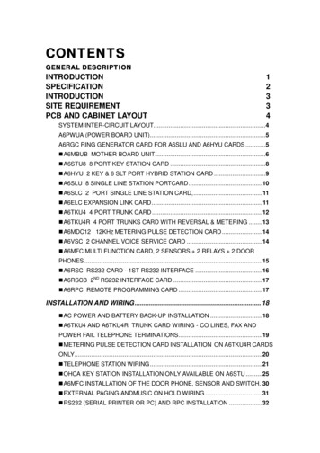
EW2044.16USER MAUNALEW20 PCB & Cabinet LayoutThree-View Drawing Of EW20Aristel Group
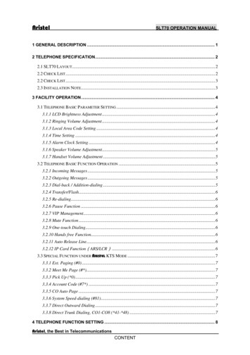
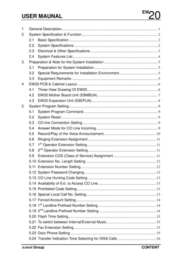
USER MAUNAL4.2EW20EW20 Mother Board Unit (E8MBUA)1、 EPU Expansion Connector2、 EPU Power Supply Connector3、 Mother Board LED4、 Fuse (250V/2A)5、 External Music Resource Connector6、 System Power Connector (USB form)7、 CO Line Ports : CO1 and CO28、 Grounding9、 Extensions Ports: 01 08 (Factory default extension No.: 801 808).Aristel Group7
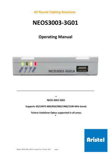
EW204.3USER MAUNALEW20 Expansion Unit (E8EPUA)1、 EPU Data Connector2、 EPU Power Connector3、 CO Line Ports: CO3 and CO44、 Extensions Ports: 09 16 (Factory default extension No.: 809 816)8Aristel Group
EW20USER MAUNAL55.1System Program SettingSystem Program Command# * 10 [System Password]All settings are available only under the system program Command and can be done by anyextension.To enter the system program Command:(1) Off hook to hear the dial tone;(2) Press # * 10, enter the System Password (5 digits);(3) The system comes into the program mode while hearing the dial tone again;(4) Enter the required setting. Hear the dial tone when setting is successful;(5) Repeat Step (4) to continue other settings.Note:① The default system password is 00000; Please reset the system before commencingsystem program at the first time.② other settings can be continued. However, if the setting failed, you will hear a busy tone,then please “hook flash” or press the “Flash” Key to hear a dial tone and continue thesettings.③ ** is to indicate all the extensions (*** for 3 digits extension number and **** for 4digits); while 9 is to indicate all the CO lines.5.2System Reset# * 20 [System Password]This setting is to restore all the setting values to factory default.(1) Enter the system program Command, then press # * 20, enter the System Password(5-digits);(2) Dial tone is heard to confirm successful reset after a pause of about three seconds.5.3CO line Connection Setting# * 11 [CO Line No.] [0/1]When one channel of CO lines is not used, it must be set as not connected to keep the useraway from the access to a non-existent CO line.(1) Enter the system program Command, then press # * 11, CO Line No., then press M;M 0not connected.M 1connected;(2) Dial tone will be heard if the setting is successful.Note: The default setting for all the CO lines is as connected;5.4Answer Mode for CO Line Incoming# * 12 [CO Line No.] [Answer Mode]Each CO line can be assigned as either of the two modes to answer the incoming calls:. Ring the assigned extensionAristel Group9
EW20USER MAUNAL Answered by auto-attendant.(1) Enter the system program Command, then press # * 12, CO Line No. and M;M 0Ring the assigned extensionM 1Answered by Auto-attendant.(2) You will hear dial tone if the setting is successful.Note: The factory default setting is Ring Mode5.5Record/Play of the Voice Announcement# * 13 [Record/Play: M] [Segment: N]When in auto-attendant mode, the system will provide voice announcement for the externalcaller to directly access an extension. The users can record the message as they preferred.There are three segments of voice announcement in total. The first is greeting message, thesecond is “Extension Busy” Announcement and the third is “No answer” Announcement.M 1to Record message;M 2to Play message.N indicates the Segment, N 1 3;Operation of recording the first segment:(1) Enter system program Command, then press # * 13 1 11 indicates to record and 1 indicates the Segment 1(2) Record the first segment of message after hearing a prompt sound “Di”(3) On-hook to finish recording;(4) Repeat the above three steps to record the massage of Segment 2 and Segment 3.Note:Always begin recording after the “Di” sound is heard. The first segment is for greeting message such as “Please dial the extension number. Foroperator please dial 0.” The second is for “Extension Busy” Announcement, such as “The extension you dialed isbusy now, please dial later or call other extension”. The third segment is for “No answer” Announcement, such as “The extension you dialed isno answer, please dial later or call other extension”. The Segment 2 and Segment 3 will be erased when the first Segment 1 is recorded; TheSegment 3 will be erased when the Segment 2 is recorded. Please refer to the following suggestions while recording the message.a. Choose a quiet environmentb. Always use handset instead of microphone (Hands free)c. Press the hook immediately after finishing recording.10Aristel Group
EW20USER MAUNAL5.6Ringing Extension Assignment# * 14 [Ext. No.] [CO Line No.] [1/0]Under the mode of Ringing assigned extension for incoming calls, when there is an incomingcall, the assigned extension will ring; The operator extension will ring if no ringing extension isstassigned. If the1 operator extension is not answered within 25 seconds, the 2sttogether. While if the 1 one is busy, the 2ndndone will ringone will ring immediately.To assign the Ringing Extension:(1) Enter the system program Command, then press # * 14, Extension No., CO Line No., then1;(2) When the dial tone is heard, the extension is set as the ringing extension for thecorresponding Co line.To disable the Ringing Extension:Press # * 14,Extension No., CO Line No., then 0.To disable all the Ringing Extension:Press # * 14,and *** (or **,or **** depending on the extension No. length), CO Line No., then 0.Note:An extension can be set as ringing extension for more than one CO line and one CO line can beassigned more than one ringi
Aristel Group 1 EW20 1 General Description Thanks for choosing our Aristel EW20 telephone switching system. . This User manual gives clear descriptions of all the steps for installation and operation. If you have any queries, please contact your . Ph