Transcription
CONTENTSGENERAL TE REQUIREMENTPCB AND CABINET LAYOUT12334SYSTEM INTER-CIRCUIT LAYOUT.4A6PWUA (POWER BOARD UNIT).5A6RGC RING GENERATOR CARD FOR A6SLU AND A6HYU CARDS .5! A6MBUB MOTHER BOARD UNIT.6! A6STU8 8 PORT KEY STATION CARD .8! A6HYU 2 KEY & 6 SLT PORT HYBRID STATION CARD .9! A6SLU 8 SINGLE LINE STATION PORTCARD.10! A6SLC 2 PORT SINGLE LINE STATION CARD,.11! A6ELC EXPANSION LINK CARD.11! A6TKU4 4 PORT TRUNK CARD .12! A6TKU4R 4 PORT TRUNKS CARD WITH REVERSAL & METERING .13! A6MDC12 12KHZ METERING PULSE DETECTION CARD .14! A6VSC 2 CHANNEL VOICE SERVICE CARD .14! A6MFC MULTI FUNCTION CARD, 2 SENSORS 2 RELAYS 2 DOORPHONES .15! A6RSC RS232 CARD - 1ST RS232 INTERFACE .16! A6RSCB 2ND RS232 INTERFACE CARD .17! A6RPC REMOTE PROGRAMMING CARD .17INSTALLATION AND WIRING. 18! AC POWER AND BATTERY BACK-UP INSTALLATION .18! A6TKU4 AND A6TKU4R TRUNK CARD WIRING - CO LINES, FAX ANDPOWER FAIL TELEPHONE TERMINATIONS.19! METERING PULSE DETECTION CARD INSTALLATION ON A6TKU4R CARDSONLY.20! TELEPHONE STATION WIRING.21! OHCA KEY STATION INSTALLATION ONLY AVAILABLE ON A6STU .25! A6MFC INSTALLATION OF THE DOOR PHONE, SENSOR AND SWITCH. 30! EXTERNAL PAGING ANDMUSIC ON HOLD WIRING .31! RS232 (SERIAL PRINTER OR PC) AND RPC INSTALLATION .32
AV-38 INSTALLATION MANUALINTRODUCTIONARISTEL AV-38 Telephone System minimum configuration of 4 CO Lines 8 Stationscan be readily expanded to 12 CO Lines 26 Stations.It is quite versatile and uses:"# IAPX8088 microprocessor for it’s main processing unit."# Unique ARISTEL ASCII Chip “A-SERIES6A F98250000” (200 pins)."# Additional Processor chips for tasking-sharing between the system and keytelephone."# Space Division Matrix for the network switching.!#AV38 SYSTEM MODULESMODELDESCRIPTIONA6408K Main Service Unit, Basic configuration of 408A6TKU4 Trunk Card (4 Ports), consisting of 4 CO LinesTrunk Card (4 Ports), 4 CO Lines with LineA6TKU4RReversal Metering Pulse Detection FacilityA6STU8 Key Station Card (8 Ports), 8 Key StationsHybrid Station Card, 2 Key Stations 6 Single LineA6HYUTelephonesSingle Line Station Card, 8 Single LineA6SLUTelephonesSingle Line Station Card, 2 Single LineA6SLCTelephonesRing Generator Card, provides ring for single lineA6RGCtelephones on A6HYU and A6SLUExpansion Intercom Link Card, provides 8A6ELCadditional intercom linksA6VSC Voice Service Card, 2 60 second Voice Channels.Multi Function Card 2 Door Stations 2 Relays 2A6MFCSensorsRS232 Card, providing an RS232 serial port forA6RSClocal programming, SMDR and CNDRS232 Card, providing 2nd RS232 serial port forA6RSCBSMDR and CND (Takes the place of the A6RPC)Remote Programming Card, standard modemA6RPC2400 bps for remote programmingWARNINGS!REMARKBasic UnitExpansion CardExpansion CardExpansion CardExpansion CardExpansion CardExpansion CardOptional CardOptional CardOptional CardOptional CardOptional CardOptional CardOptional CardThis equipment MUST be installed by a licensed installer and maintained byqualified service personnel.The mains power lead MUST be connected before any other cabling or ahazardous condition may occur.When servicing, disconnect all cablingbefore removing the mains power lead or a hazardous condition may occur.AV-38 INSTALLATION MANUAL Issued March 20011-1
AV-38 INSTALLATION MANUALSPECIFICATIONS!#GENERAL SPECIFICATIONCO Lines4 12DSS64 Consoles1 maxKey Telephones2 24Single Line Telephones2 26Intercom Paths (Local)1 9Power Failure Transfer Phone (PFT)Lines 1 and 2 of each Trunk CardDoor Phones2Relay Switches2Sensor Interfaces2Fax MonitorLine 4 of each Trunk CardLine Reversal12 maxMetering Pulse Detection12 maxRS232 for SMDR1Remote Programming1Speed Dial700 sets!#ELECTRICAL & OTHER SPECIFICATIONSInput AC VoltageSystemPowerKey TelephoneConsumption SLTDoor PhoneSystem Power Back-Up BatteryKey TelephoneDoor PhoneLoopSLTResistanceExternal PagingCO LineOutgoing DialingDialing SignalIntercom DialingTypeRelay Switch Contact RatingFunctionSystem Dimension (mm, W D H)Key Telephone Dimension (mm)Working TemperatureWorking HumiditySwitch ModeControl Mode1-2230 VAC 15% (50/60 Hz)/0.42Amps60 W2.0 W max.0.85 W0.5 W1 2 Hour (24 VDC 6.5AH)40 Ω max.40 Ω max.400 Ω max.600 Ω max.1.5K Ω max.Tone / PulseTone / Pulse / DigitalOSPDT7A/230VACDoor Switching, Paging, Music on Hold, , etc.364 90 425230L 180W 75H0 0C 45 0C (32 0F 113 0F)10% 90% relative non-condensingSpace Division Matrix (SDM)8/16 bits CPU, Registered ProgramAV-38 INSTALLATION MANUAL
AV-38 INSTALLATION MANUALINTRODUCTIONINTRODUCTIONThis manual provides the detailed procedures for installing the ARISTEL AV-38Key Telephone System. Read this entire section before proceeding with the actualinstallation.Prior to installation carefully inspect all packages for evidence of damage and comparethe equipment received against equipment ordered to ensure ALL components havebeen received.SITE REQUIREMENT # The Key System Unit (KSU) should be installed in a clean, dry and secure locationaccessible only by authorized personnel.The location must have adequateventilation and the temperature range within 0 45o C with a 10 90%non-condensing relative humidity. # The installation site should have sufficient room to mount the KSU on a wall, alongwith the necessary connecting blocks and ancillary equipment. The installation siteshould not be in areas subject to static electricity (eg. dry copiers, electric welders), orvibration (eg. heavy machinery). # It is the customer’s responsibility to provide a dedicated 240VAC/50Hz 10 Amp mainspower outlet. Line Isolation Units (LIUs) must be provided if an external music sourceor optional external paging equipment is installed.AV-38 INSTALLATION MANUAL Issued March 20011-3
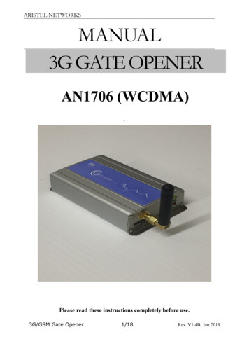
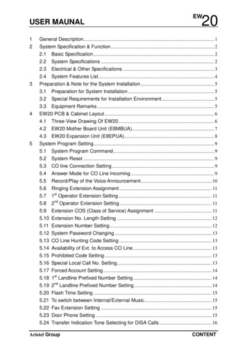
AV-38 INSTALLATION MANUALPCB AND CABINET LAYOUT!#SYSTEM INTER-CIRCUIT LAYOUT1.Figure 1. System Inter-Circuit LayoutAC Power Inlet.2.AC Power Switch.3.Power Indicator (LED Type).4.DC Power Switch.5.AC Power Ground (F.G.).6.RJ11 for SLT Connection to A6SLC.7.2-Wire Female Connector. (For External Battery Box Connection)8.Earth Ground (For Lightning Protection Ground) provided by M.E.N.9.Wiring Area and the Cable Outlet.10. RS232-1 (Female DB9) for the connection to the 1st RS232 (A6RSC).11. RS232-2 (Female DB9) for the connection to the 2nd RS232 (A6RSCB)1-4AV-38 INSTALLATION MANUAL
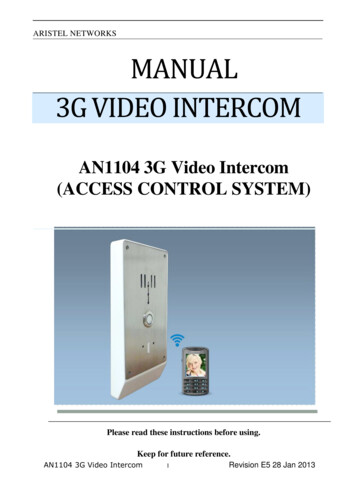
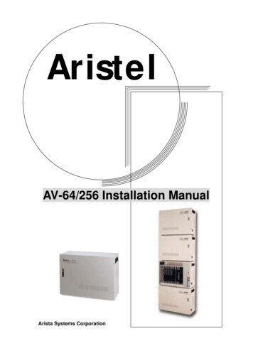
AV-38 INSTALLATION MANUAL!#A6PWUA (POWER BOARD UNIT)1.CN101Figure 2. A6PWUA (Power Board Unit): AC Power Inlet.2.SW101: AC Power Switch.3.LED501 : Power Indicator.4.SW401: DC Power Switch.5.CN105: AC Power Earth Grounding Connection Point.6.CN401: 24VDC Connection Points; Left Side is ( ), Right Side is (-).7.CN402: Backup Battery Connector.8.CN301: Connect to [POWER] position on A6MBUB by the cable.9.CN801: Connect to [SPWR] position on A6MBUB by the cable.10. CN802: Connect to [CN901] position on A6RGC by the cable.!#A6RGC RING GENERATOR CARD FOR A6SLU and A6HYU CARDSFigure 3. A6RGC (Ring Generator Card)1.CN901: 4-Wire Connector. Connect to [CN802] on the A6PWUA.2.CN902: 2-Wire Connector. Connect to [RING] the A6MBUB.AV-38 INSTALLATION MANUAL Issued March 20011-5
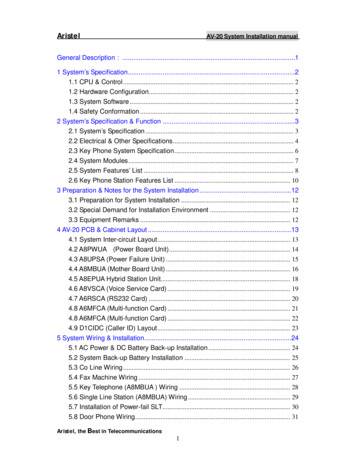
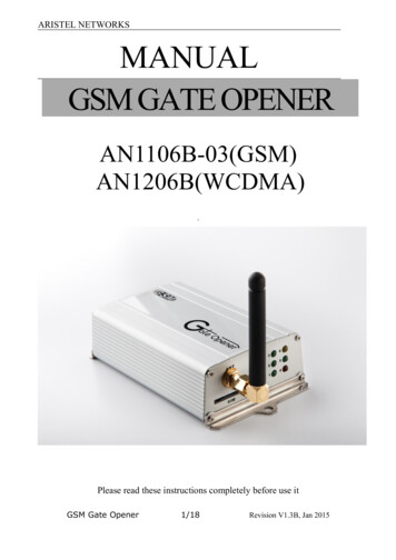
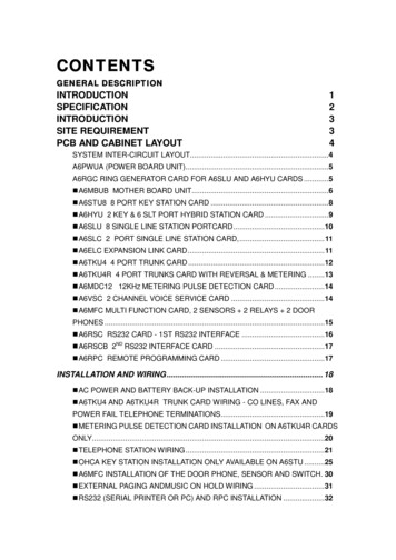
AV-38 INSTALLATION MANUAL!#A6MBUB MOTHER BOARD UNITFigure 4. A6MBUB (Mother Board Unit)1-6AV-38 INSTALLATION MANUAL
AV-38 INSTALLATION .19.20.21.22.23.RINGSPWRPOWERSLCPWR1: 2-Wire Connector. Connect to [CN902] position on A6RGC.: 2-Wire Connector. Connect to [CN801] position on A6PWUA.: 6-Wire Connector. Connect to [CN301] position on A6PWUA.: Connector for the A6SLC Card.: 4-Wire Connector for the FIRST Station Unit to be connected.Connect to [PWR] position on A6STU8 or A6HYU or A6SLU.PWR2: Same as [PWR1] but it is used for the SECOND Station Card.PWR3: Same as [PWR1] but it is used for the THIRD Station Card.STA1: Connector Slot for the FIRST Station Card to be connected.Connect to [STA] position on A6STU8 or A6HYU or A6SLU.STA2: Same as [STA1] but it is used for the SECOND Station Card.STA3: Same as [STA1] but it is used for the THIRD Station Card.STU1: Connector Slot for the FIRST Station Unit to be connected.Connect to [STU] position on A6STU8 or A6HYU or A6SLU.STU2: Same as [STU1] but it is used for the SECOND Station Card.STU3: Same as [STU1] but it is used for the THIRD Station Card.CON4: Connect to [CON4] position on A6ELC. Required when the THIRDTrunk Unit is installed in the system.CON3: Same as [CON4], but connect to [CON3] position on A6ELC.TKU1: Connector Slot for the FIRST Trunk Card. Connect to [TKU] position onA6TKU4 or A6TKU4R.TKU2: Same as [TKU1], but it is used for the SECOND Trunk card.TKU3: Same as [TKU1], but it is used for the THIRD Trunk Card.SW2: Audio signal level control for both intercom and external paths. If theTHIRD Trunk Card is installed, then switches “1, 2, 3 & 4” mustbe SWITCHED OFF. (Default should be ALL ON)EXTMP : External Page and External Music Source connection.SVR: Volume adjustment for the External Music Source.MFC: Connector for the A6MFC Card.MOH: Music Source selection for Music On Hold.24. BGM25. RSC26. BAT: Music Source selection for Back Ground Music. (The jumper settingsfor internal and external selection are the same as the Music Source).: Connector for the A6RSC Card as the FIRST RS232: 3 VDC, 180 mA/H Li-Battery to back-up the system programming dataduring AC power Off. SW1 must be ON for the battery to retain memoryduring power fail.27.28.29.30.31.32.33.34.: To turn the memory backup Battery ON or OFF.: Connector for the A6RPC Card: Factory Use Only: Connector for the A6VSC.: System Software EEPROM.: EH64 connector.: Same as [CON1].: Power connector for SLC card.SW1RPCLCDVSCU3CON1CON2SLCPAV-38 INSTALLATION MANUAL Issued March 20011-7
AV-38 INSTALLATION MANUAL!#A6STU8 8 PORT KEY STATION CARD1.EXT: Amp Connector for Key Station Wiring2.CON4: Connector for the A6ELC when the THIRD Trunk Unit is installed.3.STU: 12-Wire Connector Cable. Connect to [STU] position on A6MBUB.4.STA: 62-Wire Connector Cable. Connect to [STA] position on A6MBUB.5.PWR: 4-Wire Connector to [PWR] position on A6MBUB.6.CON3: Same as [CON4], but connect to [CON3] position on A6ELC.Figure 5. A6STU8 8 Port Key Station Card1-8AV-38 INSTALLATION MANUAL
AV-38 INSTALLATION MANUAL!#A6HYU 2 KEY & 6 SLT PORT HYBRID STATION CARDFigure 6. A6HYU 2 Key & 6 SLT Station Port Hybrid Station Card1.EXT: 25-Pairs Amp connector used for Key Station and SLT wiring.2.CON4: Connector for the A6ELC when the THIRD Trunk Unit is installed.3.STU: 12-Wire Connector Cable. Connect to [STU] position on A6MBUB.4.STA: 62-Wire Connector Cable. Connect to [STA] position on A6MBUB.5.PWR: 4-Wire Connector to [PWR] position on A6MBUB.6.CON3: Same as [CON4], but connect to [CON3] position on A6ELC.AV-38 INSTALLATION MANUAL Issued March 20011-9
AV-38 INSTALLATION MANUAL!#A6SLU 8 SINGLE LINE STATION PORTCARDFigure 7. A6SLU 8 Port Single Line Station Card1.EXT: 25-Pairs Amp connector used for SLT wiring.2.CON4: Connector for the A6ELC when the THIRD Trunk Unit is installed.3.STU: 12-Wire Connector Cable. Connect to [STU] position on A6MBUB.4.STA: 62-Wire Connector Cable. Connect to [STA] position on A6MBUB.5.PWR: 4-Wire Connector to [PWR] position on A6MBUB.6.CON3: Same as [CON4], but connect to [CON3] position on A6ELC.1-10AV-38 INSTALLATION MANUAL
AV-38 INSTALLATION MANUAL!#A6SLC 2 PORT SINGLE LINE STATION CARD,Figure 8. A6SLC 2 Port Single Line Station Card1.CN1: Connector for the installation of the RJ11socke.SLT1 : The 1st Single Line Station Port. Pins 3&4 of RJ11 socket.SLT2 : The 2nd Single Line Station Port. Pins 1&6 of RJ11 socket.2.W1: Earth Grounding Connection Point. Connect to [CN105] position onA6PWUA.3.SLC: Connect to [SLC] position on A6MBUB.4.CN2: Connect to [SLCP] position on A6MBUB.!#A6ELC EXPANSION LINK CARDFigure 9. A6ELC Expansion Link Card1.2.CON4: 10-Pin Connector on A6MBUB, A6STU8, A6HYU and A6SLU when theTHIRD Trunk Card is installed.CON3: 20-Pin Connector on A6MBUB, A6STUB8, A6HYU and A6SLU whenthe THIRD Trunk Card is installed.NOTE:A6ELC CARDS MUST BE INSTALLED ON ALL 8 PORT STATION CARDSAND THE A6MBUB WHEN THE THIRD TRUNK CARD IS INSTALLED. ALSO,ALL 4 SWITCHES (SW2) ON THE A6MBUB MUST BE TURNED OFF.AV-38 INSTALLATION MANUAL Issued March 20011-11
AV-38 INSTALLATION MANUAL!#A6TKU4 4 PORT TRUNK CARDFigure 10. A6TKU4 4 Port Trunk Card1.CON2: Dual RJ11-6P6C Connector. For the connection of FAX Machineand Power Failure Transfer Phones (PFT).FAXM : For the FAX Machine Connection, it is paralleled with the 4thCO Line Port and worked as FAX MONITOR function.PFT1 : For the 1st Power Failure Telephone Connection of [CO1] Pins3&4.PFT2 : For the 2nd Power Failure Telephone Connection of [CO2] Pins1&6.2.CON1: Dual RJ11-6P6C Connector. For the connection of CO Lines(POTS Lines
AV-38 INSTALLATION MANUAL INTRODUCTIONINTRODUCTION ARISTEL AV-38 Telephone System minimum configuration of 4 CO Lines 8 Stations can be readily expanded to 12 CO Lines 26 Stations. It is quite versatile and uses: "#IAPX8088 microprocessor for it’s main processing unit. "#Unique ARISTEL ASCII Chip “A-SERIES6A F98250000” (200 pins).