Transcription
DSSDynamic SpectrumSharing(5G)White Paper
DSSIntroductionOperators across Europe, Asia and North America have been commercially launching 5G services at an incredible pacenever before seen in any previous cellular network generation. From the spectrum perspective, we have seen a nearlysimultaneous commercial launches in both FR1 (below 7.125 GHz) and FR2 (millimeter wave). Most FR1 networks havebeen deployed at mid-bands with a focus on delivering 5G services in 100MHz with higher capacity, for example in n78.While 5G users in such high bandwidth are able to enjoy the benefits of eMBB services, there are obvious andexpected challenges that have emerged alongside these deployments. With each new generation of cellularcommunications the frequencies used get increasingly higher, unlocking more bandwidth, but at the same timeshrinking the cell coverage area. In 5G, both coverage and capacity are important aspects, especially in early stage ofdeployment, with a need for indoor penetration in densely populated urban areas as well as with the coverage of vastrural space outside the cities.These challenges have been anticipated and there is an obvious solution in sight to provide the coverage layer for 5Gin low bands. But obstacles still remain – almost all accessible low bands are occupied by existing technologies, suchas LTE. There are still few options on the table, for example 700 MHz across Europe or 600 MHz in the U.S, yet suchoptions are quite limited both in bandwidth and availability. This inevitably raises the question of re-farming thespectrum from LTE to NR. However, despite the tremendously successful uptake of 5G, the industry expects thatmost of the traffic in the upcoming years will still be carried by LTE networks till 5G device penetration exceeds that ofLTE.Re-farming low band carriers from 4G without a corresponding increase in 5G devices penetration might lead tocongestion of the remaining LTE carriers, degrading indoor coverage for LTE users who still represent the majority ofthesubscriber base. In previous generations it took years to start re-farming; for instance from 2G to 3G and from 2G/3Gto 4G. In case of 5G, learning from this experience has led to coverage enhancement solutions that allow a ‘soft’ andflexible re-farming: a “Spectrum Sharing” technique between 4G and 5G, providing a coexistence between 5G and 4G.Spectrum sharing can be implemented in a static or dynamic manner. The first option means that there will bea dedicated carrier for each technology within the same band. While it has one benefit – it’s transparent to the UE –the spectrum efficiency is insufficient. LTE-only users, currently being a majority, will suffer diminished throughput.Partially or fully overlapped LTE and NR carriers mean the transition is more efficient 5G and 4G coexistence, DynamicSpectrum Sharing (DSS).The DSS concept is based on the flexible design of NR physical layer. It uses the idea that NR signals are transmittedover unused LTE resources. With LTE, all the channels are statically assigned in the time-frequency domain, whereasthe NR physical layer is extremely flexible for reference signals, data and control channels, thus allowing dynamicconfigurations that will minimize a chance of collision between the two technologies.One of the main concepts of DSS is that only 5G users are made aware of it, while the functionalities of the existingLTE devices remain unaffected (i.e. LTE protocols in connected or idle mode). Therefore, fitting the flexible physicallayer design of NR around that of LTE is needed in order to deploy DSS on a shared spectrum. This paper discusses thevarious options of DSS implementation, including deployment challenges, possible impacts to data rates, and areasof possible improvements.DSS Deployment Options and ScenariosMBSFN and non-MBSFN DSS Based Deployment OptionsNR offers a scalable and flexible physical layer design depicted by various numerologies. There are differentsubcarrier spacing (SCS) for data channels and synchronization channels based on the band assigned. This flexibilitybrings even more complexity because it overlays the NR signals over LTE, which requires very tight coordinationbetween gNB and eNB in order to provide reliable synchronization in radio scheduling.2PDFDSSWP 0220Copyright 2020 MediaTek, Inc. All rights reserved.
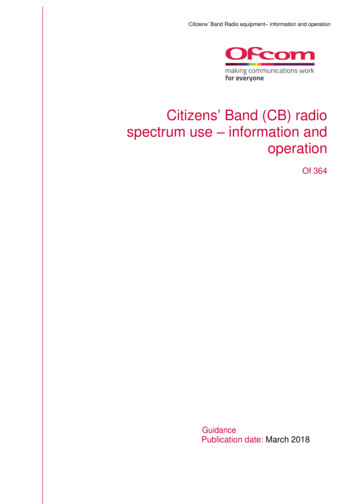
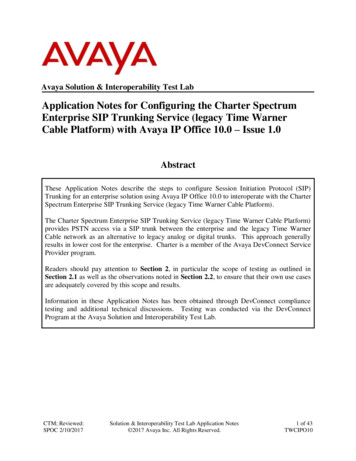
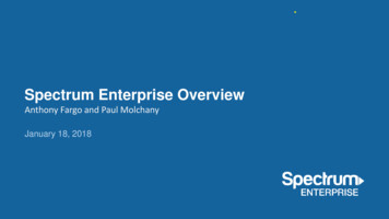
DSSLTE CRSand PDCCHLTE CRSRB level ratematchingRE level ratematchingNR overlayOption-1: MBSFN-basedOption-2: Mini-slot-basedOption-3: Rate-matching-basedFigure 1. DSS Deployment OptionsThe main foundation of DSS is to schedule NR users in the LTE subframes while ensuring no respective impact on LTEusers in terms of essential channels, such as reference signals used for synchronization and downlink measurements.LTE Cell Reference Signals (CRS) is typically the main concept where DSS options are designated, as CRS have a fixedtime-frequency resource assignment. The CRS resources layout can vary depending on the number of antennaports. More CRS antenna ports leads to increased usage of Resource Elements (REs). CRS generates from 4.76%(1 antenna port) up to 14.29% (4 antenna ports) overhead in LTE resources. As CRS is the channel used for downlinkmeasurements, avoiding possible collision with CRS is one of the foundations of the DSS options shown infigure 1. The other aspect of DSS design is to fit the 5G NR reference signals within the subframes in a way to avoidaffecting NR downlink measurements and synchronization. For that, DSS considers the options shown in figure 1 toensure NR reference signals such as Synchronization Signal Block (SSB) or Demodulation Reference Signal (DMRS) areplaced in time-frequencies away from any collision with LTE signals.MBSFN, option 1 in figure 1, stands for Multi-Broadcast Single-Frequency Network and is used in LTE forpoint-to-multipoint transmission such as eMBMS (Evolved Multimedia Broadcast Multicast Services). The generalidea of MBSFN is that specific subframes within an LTE frame reserve the last 12 OFDM symbols of such subframeto be free from other LTE channel transmission. These symbols were originally intended to be used for broadcastservices and are “muted” for data transmission in other LTE UE. Now this idea has been adjusted for use in a DSSconcept, so that these reserved symbols are used for NR signals instead of eMBMS. While in general LTE PDCCH canoccupy from 1 to 3 symbols (based on cell load), the first two OFDM symbols of such MBSFN subframe are used for LTEPDCCH, and DSS NR UE can use the third symbol. Using MBSFN is completely transparent to legacy LTE-only devicesfrom 3GPP Release 9 onwards, as such LTE UE knows that these subframes are used for other purposes. In this sensethis is the simplest way of deploying DSS. This method has disadvantages though. The main one is that if MBSFNsubframes are used very frequently and it takes away resources from LTE users, heavily reducing LTE-only userthroughput. Note that option 1 shown in figure 1 does not require LTE MBSFN Reference Signals to be used, becausethe MBSFN subframe is used to mute the subframe for DSS operation only, and LTE CRS shall only be transmitted inthe non-MBSFN region (within the first two symbols) of the MBSFN subframe.The two other options illustrated in figure 1 are dealing with non-MBSFN subframes that contain LTE referencesignals. Option 2 is ‘mini-slot’ based; mini-slot scheduling is available in NR for URLLC applications that requireextremely low latency. The symbols can be placed anywhere inside the NR slot. In respect to DSS, mini-slotoperation just eliminates the usage of the symbols that contain LTE CRS and schedule only free ones for NRtransmission. The basic limitation of this method comes from the concept itself. It is not very suitable for eMBBapplications as too many resources are outside of NR scheduling. However it still can be utilized in some special caseslike 30 kHz SSB insertion which will be described later in this paper.Option 3 is based on CRS rate matching in non-MBSFN subframes, and it is expected to be the one most commonlyused for NR data channels. In this option, the UE performs puncturing of REs used by LTE CRS so that the NRscheduler knows which REs are not available for NR data scheduling on PDSCH (Physical Downlink Shared Channel).The implementation of this option can be either Resource Block (RB)-level when the whole RB containing LTE CRSis taken out of NR scheduling, or RE-level where NR PDSCH scheduling avoids particular REs only. The end result ofthis method is that the scheduler will reduce the NR PDSCH transport block size as the number of REs available forscheduling become less in a slot.For better spectral efficiency, CRS RE-level rate-matching is preferred when compared to RB-level rate matching inNR PDCCH/PDSCH 15 kHz SCS. However for NR PDCCH/PDSCH at 30 kHz SCS, only RB-level rate matching is suitablebecause of the difference in numerologies with LTE. Another application for RB-level rate matching is to avoidcollisions with the other LTE synchronization channels (PSS/SSS/PBCH). Table 1 compares the available REs per RB3PDFDSSWP 0220Copyright 2020 MediaTek, Inc. All rights reserved.
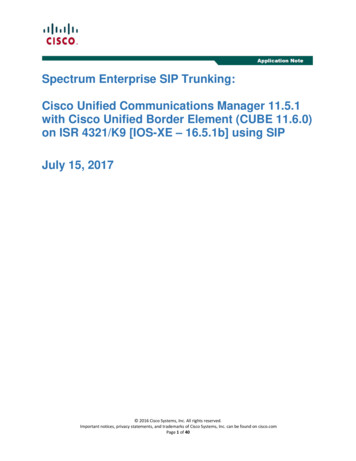
DSSin a slot, depending on the underlying LTE CRS configuration. As shown in table 1, LTE CRS within an RB occupies foursymbols (#0, 4, 7, 11) for one or two antenna ports and two additional symbols (#1, #8) for four CRS antenna ports.Each CRS symbol consists of two subcarriers for each antenna port. However, since the first two symbols are occupiedby LTE PDCCH, they are not considered for rate matching overhead of the NR PDSCH. Then, the overall overhead fromCRS to available NR PDSCH symbols becomes 3 CRS symbols * 2 subcarriers 6 RE for one antenna port, 3 CRS symbols * 4 subcarriers 12 RE for two antenna ports, and 4 CRS symbols * 4 subcarriers 16 RE for four antenna ports. AsNR PDSCH scheduling can only occur after the second symbol in the slot where the third symbols is occupied for NRPDCCH (first two symbols are for LTE PDCCH), as a result, NR PDCSCH is scheduled with 11 symbols out of the total 14symbols available in a slot. Then, 12 RE * 11 Symbols results in 132 RE available in a slot for NR PDSCH. In the case ofone LTE CRS antenna port, the total available NR PDSCH REs available in a slot per one RB is 132-6 126 REs, 132-12 120 REs with two CRS antenna ports, and 132-16 116 REs with four CRS antenna ports. On the other hand, if the entireRB in a slot is being muted, 3 (one and two CRS ports) and 4 (otherwise) symbols will be rate matched, resulting in 12RE per RB *(11 symbols available for PDSCH – 3 CRS symbols muted within NR slot) 96 REs available for NR PDSCHwith one or two CRS antenna ports, and 12 RE per RB *(11 symbols available for PDSCH – 4 CRS symbols muted withinNR slot) 84 REs available for NR PDSCH with four CRS antenna ports. This means that the transport block size for NRPDSCH will be higher in RE rate matching and hence better spectral efficiency.Table 1. RE-level vs. RB-level CRS Rate MatchingLTE CRS ConfigurationRE rate-matchingRB rate- matchingLTE 1 CRS port: 6 RE overhead in NRPDSCH region, or 3 symbols with RBRate Matching126 RE96 RELTE 2 CRS port: 12 RE overhead in NRPDSCH region, or 3 symbols with RBRate Matching120 RE96 RELTE 4 CRS port: 16 RE overhead in NRPDSCH region, or 4 symbols with RBRate Matching116 RE84 REUsing one of the DSS options does not eliminate others. Despite each one has its own advantages and disadvantages,they all can find their proper application depending on particular configuration and in some cases they can be mixedto enable an optimal DSS solution.Combining DSS Deployment Options: SSB ExampleThis section shows examples of NR SSB transmissions to demonstrate the importance of combining different DSSdeployment options. SSB consists of synchronization signals (PSS and SSS) and a Physical Broadcast Channel (PBCH).For a half frame (5 msec) SSB transmission, the SSB contains 4 OFDM symbols in the time domain and 240 contiguoussubcarriers (20 RBs) in the frequency domain.The subcarrier spacing (SCS) used for SSB is dependent on the frequency band. In case of FR1, it can be either 15 kHzor 30 kHz. In time domain, there is a number of options of SSB location depending on the band used and SCS. 3GPPTS 38.101-1 contains pre-defined tables of starting symbol indices per band, marked as Case A, B or C in FR1. Table 2illustrates SSB allocation in time domain for FR1 cases in a frequency range 3 GHz only, where DSS can be applied atthe moment. In the frequency domain, up to four SSB beams (SSBs index #0, 1, 2 and 3 with Lmax 4, configured to UEby higher layer parameter ssb-PositionsInBurst as a bitmap) can be transmitted in the FR1 range 3 GHz.Table 2. SSB Starting Symbol Indices for FR14SSB Subcarrier Spacingf 3 GHzBand Example (f 3 GHz) basedon TS 38.101-1Case A :15 kHzNR SSB Symbols within one LTE subframe (2,3,4,5),(8,9,10,11)FDD band n3, n5, or TDD band n41Case B :30 kHzNR SSB Symbols within one LTE subframe DD band n5Case C :30 kHzNR SSB Symbols within one LTE subframe DD band n41PDFDSSWP 0220Copyright 2020 MediaTek, Inc. All rights reserved.
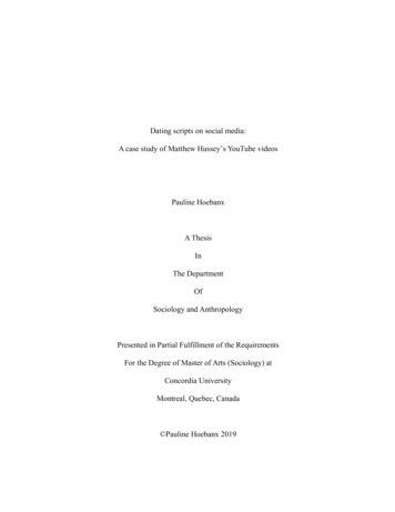
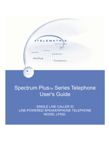
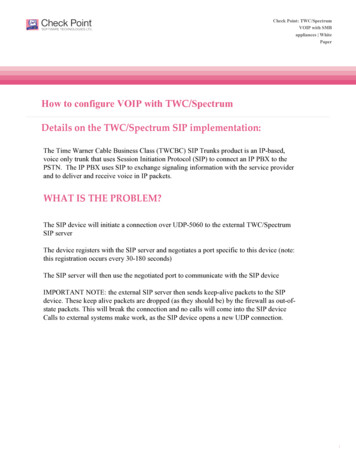
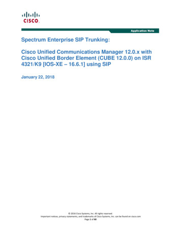
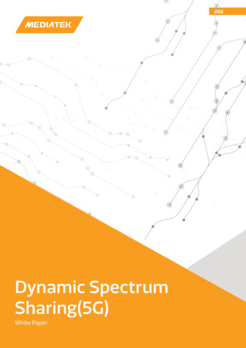
DSSAs discussed in previous section, DSS can be implemented in MBSFN or non-MBSFN subframes. For NR PDSCHchannel used for data transmission, rate matching can be used to avoid the REs occupied by LTE CRS. However,for NR SSB, puncturing the channel becomes impossible as it may affect the downlink measurements andsynchronization. Therefore, SSB in a DSS cell must be transmitted in a way to totally avoids all symbols andsubcarriers occupied by LTE CRS. To better understand whether we shall opt for MBSFN or non-MBFSN frame totransmit SSB, we need to take a look at what can be the impact in each case.Starting with non-MBSFN subframe which is shown on figure 2. The upper part of the figure depicts NR resource grid,while the lower part is the corresponding LTE non-MBSFN subframe. In this paper, it is always assumed that NRPDCCH/PDSCH SCS is 15 kHz to match the LTE subframe, which is expected to be the case used for the initial DSSimplementation. With NR PDCCH/PDSCH SCS of 15 kHz, there is one NR slot per NR subframe and 10 NR slots per NRframe. Therefore, in this paper, the terms “slot” and “subframe” are used interchangeably. The paper assumes thechannel configurations of 20 MHz bandwidth for DSS, unless mentioned otherwise.Freq (PRB) SSB #2 & #3 occupy the next 10 of SSBSSB#1SSB#0PRB#19 of SSBPRB#0 of SSB012345678910111213Time01NR SSB Symbol Index (PDSCH with15kHz, SSB with 15kHz case A)012345678910111213LTE Symbol Index (Non-MBSFN,with PDCCH and CRS)2345678910111213Time01NR SSB Symbol Index (PDSCH with15kHz, SSB with 30kHz case B)Time01234567891011LTE Symbol Index (Non-MBSFN,with PDCCH and CRS)NR SSB (Possible to transmit)NR SSB (NOT Possible to transmit)NR PDSCH (NOT Rate Matched)NR PDSCH (Rate Matched RE or RB may occur)NR DMRS (POS1, Single Symbol, CDM Group#3)1235678910111213Time13TimeNR SSB Symbol Index (PDSCH with15kHz, SSB with 30kHz case C)13Time0123456789101112LTE Symbol Index (Non-MBSFN,with PDCCH and CRS)LTE CRS REs for 1,2 portsLTE CRS REs for 4 portsLTE PDCCHFigure 2. Impact of Spectrum Sharing on NR SSB Channel: Non-MBSFNStarting with SSB 15 kHz Case A on the leftmost grid of figure 2 shows both SSB beams that can be transmitted inone NR slot (i.e. one LTE subframe) colliding with LTE CRS. This makes such configuration totally not suitable for DSS,because once any SSB symbol collides with CRS it eliminates transmission of the whole SSB beam. The central grid infigure 2 shows SSB 30 kHz Case B where all four beams can be transmitted in one slot because of wider SCS than theNR PDCCH/PDSCH 15 kHz SCS. One out of four SSB beams can betransmitted from gNB avoiding collision for SSB#0, yet other 3 bursts remain unavailable at least in LTE four antennaports scenario. In this case NR mobility can be affected as we are left with one beam only. SSB 30 kHz Case Crepresented in the right side of figure 2. Just like Case A, it has collisions with LTE CRS in all four SSB beams making itsuse impossible in LTE four CRS port scenario and limited to only one SSB beam in case LTE one or two CRS ports.Different results can be achieved using an MBSFN subframe for SSB transmission and figure 3 clearly shows why.Here, the same SSB cases as in figure 2 are demonstrated, but the frame consists of MBSFN subframe instead. SinceMBSFN mutes the entire 12 symbols of the subframe, then SSBs do not have LTE CRS collision, and the impact on allSSB cases is minimal.5PDFDSSWP 0220Copyright 2020 MediaTek, Inc. All rights reserved.
DSSE.g Subframe #1Aligned with valid MBSFNSubframe (e.g. i not#0)Freq (PRB)Aligned with valid MBSFNSubframe (e.g. 2PRB#10 of SSBSSB#0PRB#19 of SSBPRB#0 of SSBTime 0 1 2 3 4 5 6 7 8 9 10 11 12 130123NR SSB Symbol Index (PDSCH with15kHz, SSB with 15kHz case A)01234567891011124567891011121301234567891301LTE Symbol Index (MBSFN,with PDCCH and CRS)234567891011101112130NR SSB (NOT Possible to transmit)NR PDSCH (NOT Rate Matched)NR DMRS (POS1, Single Symbol, CDM Group#3)212130LTE CRS REs for 1,2 portsLTE CRS REs for 4 portsLTE TE Symbol Index (MBSFN, with PDCCHand CRS)LTE cell-specific referencesignals and PDCCH shallonly be transmitted in thenon-MBSFN regionof the MBSFN subframeFigure 3. Impact of Spectrum Sharing on NR SSB Channel: MBSFNThe only limitation for SSB Case C comes from LTE PDCCH and CRS transmitted in the first two symbols of thesubframe which cause collision with SSB#0 making three SSBs available out of four. However, for MBSFN case,subframe alignment with NR SSB slots is essential. Not all subframes can be allocated as MBSFN (e.g. forLTE-FDD, subframes #0 and #5 are not used for MBSFN as discussed in later sections). Therefore, not all SSBbeams can be valid for MBSFN subframes. For SSB Case A, SSB #0 and #1 cannot be transmitted within MBSFNpattern if thecorresponding slot is aligned to MBSFN subframe #0. To solve this, the cell can allocate SSB beam #2 and/or#3 that are transmitted in the second slot, which fall within a valid MBSFN subframe #1. For SSB Case B and Cwith 30 kHz SCS, all four SSBs would fall into LTE subframe #0 if fully aligned with LTE subframes. In this case,LTE and NR frame alignment is needed in a way SSB slot overlaps exactly within possible MBSFN subframesother than #0 or #5 (e.g. SSB can start at NR slot aligned with one of valid LTE MBSFN sync subframes).This SSB mapping perfectly demonstrates the importance of combining different DSS options. MBSFN-basedDSS is not usually optimal for data, to avoid backward impact to LTE throughput. However, using MBSFNsubframe is important in providing SSB transmission based on the SSB SCS, thus a preferred DSS solutionwould be to mix of both methods. This is especially important for the majority of 3 GHz bands that are theones most anticipated for DSS usage since they are restricted to SSB case A or B (except for n41 that cansupport SSB cases C with 30 kHz SCS). In general for 3 GHz bands, 3GPP in TS 38.213 states that if a 30 kHzSS/PBCH block SCS is indicated by subcarrierSpacing, Case B applies for frequency bands with only 15 kHz SSBSCS defined in TS 38.101-1.DSS Related Features in 3GPPThe design concepts of DSS on the network side discussed in the previous section require features to be supported bya DSS capable UE. The most important features are summarized in table 3 and those essential for the initialdeployment will be described in more details in this section. The table comes with a reference to 3GPP TS 38.822containing Layer 1 Feature List Index and TS 38.331 RRC Field Names, if applicable. Not every DSS deployment optionrequires all
The DSS concept is based on the flexible design of NR physical layer. It uses the idea that NR signals are transmitted over unused LTE resources. With LTE, all the channels are statically assigned in the time-frequency domain, whereas the NR physical layer is extremely flexible for reference signals, data and