Transcription
CENTURY IIIAUTOPILOT FLIGHT SYSTEMPILOT’S OPERATING HANDBOOKNOVEMBER 199868S25
68S25NOTICEThis manual contains General Information onoperation of Century III Autopilot. specific FAAapproved information on Special Techniques,Limitations and Emergency Procedures for aparticulate model airplane are contained ineither an Airplane Flight Manual Supplement ora placard. Be sure and familiarize yourself withthe information contained therein before flight.2
68S25REVISION LOGOriginal dated March 1981Revision 1 dated November 1998Pages and Figure Drawings renumbered and book reformatted in computer.3
68S25INTRODUCTIONThe Century Flight Systems, Inc. Century III is a light weight (18 lbs.)automatic flight system utilizing an advanced electronic design formaximum performance and utility. Operating on the versatile andadaptable 5000 cycle audio frequency, the Century Flight Systems, Inc.Century III represents a new design concept in which the conventionalfollow up, or control position feed back signals, are replaced by solid stateanalytical computers. In addition to providing a more stable andadaptable auto-pilot platform for advanced navigational coupling, this newsystem can cope with uneven fuel loads directional mis-trim and powerchanges without the usual directional errors, altitude losses, or commandchange requirements.Roll and pitch responses are time controlled for human-like control actionand smooth attitude transactions.This manual describes the basic characteristics of each control functionand its relationship to other functions in the flight system. Maximum utilitywill be realized after familiarization and practice.4
68S25TABLE OF CONTENTSNOTICE . 2REVISION LOG . 3INTRODUCTION . 4TABLE OF CONTENTS . 5COMMAND CONSOLE . 6Roll (Aileron) Engagement . 6Roll Command Knob . 7Heading Mode. 7Course Selector . 7Aircraft Trim Effects . 8Trim Indicator and Pitch Command Wheel . 8Pitch (Elevator) Engagement. 9Altitude Hold . 9AUTOMATIC TRIM OPERATIONS . 10GENERAL OPERATIONS. 10Pilots Preflight Procedures . 11Trim Check. 12AIR FILTER . 13Filter and Element . 13LATERAL GUIDANCE SYSTEM. 14Omni Mode. 15Nav Mode . 15Heading Mode. 16Localizer (Normal) Mode. 16Localizer (Reverse) Mode . 16Lateral Guidance System Operation. 17VOR Navigation . 18VOR Approach . 20ILS Approach - Normal. 22ILS Approach - Back Course . 24INTERCEPT CHARACTERISTICS. 26LOCALIZER AND/OR GLIDESLOPE COUPLER . 28ILS Approach Procedures . 30Limited Warranty Century Flight Systems Autopilot . 325
68S256
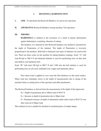
68S25COMMAND CONSOLEThe Century III console is designed to provide convenient fingertip command of allbasic autopilot functions. Magnetic engage and mode switches are designed withlogical interlocking features for operational ease and simplicity. The lucite facepanel incorporates optically engineered night lighting with provisions for dimmingcontrol through the standard aircraft rheostat.FIG. 1ROLL (AILERON) ENGAGEMENTThe Century III is separated into two distinct systems, theRoll/Heading and Pitch/Altitude.Each is engagedseparately by means of a fail safe electronic servoengage mechanism.FIG. 2Because the roll is first in logical sequence. the rollengage acts as an autopilot master switch. In thiscapacity the roll must be engaged for all other engageand mode switches to become operative. With this rollswitch only engaged, the autopilot is responsive only tothe roll axis of the attitude gyro and the commands of theconsole roll/turn control.7
68S25ROLL COMMAND KNOBFIG. 3The roll command knob controls the roll axis of theaircraft when roll mode switch is engaged. It is useful inmaneuvering and will permit steeper bank angels (up to30 ) than those resulting from D.G. heading commands.When the heading mode switch is engaged the roll knobis removed from the autopilot circuit and is ineffective.However, it should be left in the centered position forconvenience.NOTE: Do not use roll mode during approach configuration on twin engineaircraft as engine failure will result in excessive heading deviation.HEADING MODEFIG. 4FIG 5The heading mode switch is located directly adjacent andto the right of the roll engage switch. It is the function ofthe heading mode switch to remove the roll commandknob from the autopilot circuit and add the D.G., headingcommand and coupler functions to the basic roll attitudecontrol. This switch is interlocked with the roll engage sothat the roll function will be engaged simultaneously withthe heading mode switch. Prior to engagement of theheading mode, the D.G. course selector and couplermodes should be set. (See sections on coupler operationwhen optional coupler is installed.)COURSE SELECTOR D.G.The course selector D.G. replaces the standarddirectional gyro and provides a fully visible courseindicator around the normal D.G. opening. The D.G. dialis marked in 5 intervals and numbered each 30 aroundits azimuth. A center indice is provided at the top to alignselected headings. Additional indices are located each45 to facilitate rapid turn selection without mentalarithmetic. Any heading may be selected, either before orafter engagement, and turns up to 180 may beprogrammed directly, either right or left. If the courseindicator is rotated beyond 180 from the D.G. cardheading, the course selector will command a reversal inbank to reach the resultant selected heading in theshortest direction.8
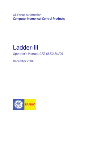
68S25The D.G. card is normally set to the magnetic compass with the caging knob on theleft in the usual fashion, while the course selector indicator is rotated by the headingknob on the right. Direction of rotation of both the knob and indicator commands thesame direction of turn.FIG. 6AIRCRAFT TRIM EFFECTSAn important axiom to remember is that if the airplane is properly trimmed, aCENTURY FLIGHT SYSTEM INC. autopilot in heading mode will never fly theairplane with a wing down.This statement can be changed slightly to apply to an airplane without an auto pilot:In order to fly a trimmed airplane on a constant heading, the wings must be heldlevel.Consider the effect of rudder trim in the above drawing (Fig. 6). Viewing the airplanefrom the rear, note that with left rudder applied the right wing must be lowered tooffset the rudder effect and keep the heading constant, i.e. the left turn effect of therudder is canceled by the right turn effect of the bank.Since the Century III is slaved to heading, this is exactly what it will do in order tohold a heading when the rudder is out of trim.Thus when operating on autopilot heading mode the pilot knows rudder trim in thedirection toward the low wing is required.TRIM INDICATOR AND PITCH COMMAND WHEELPrior to the engagement of the pitch axis, it is desirable toadjust the autopilot pitch to match the attitude being flownin, this way the pilot can transition from hand flight toautopilot smoothly during the climbout or other pitchmaneuvering. The pitch servo effort meter (trim) to theleft of the pitch control wheel indicates the position of thepitch command wheel with relation to the attitude beingFIG. 7flown.Thus, if it is pointing upward prior to engagement it indicates that the aircraft can beexpected to increase pitch attitude upon engagement, conversely a down meterindicates pitch attitude will be decreased upon engagement. The pitch commandwheel is in the autopilot circuit when the pitch mode switch only is engaged. It isremoved from the circuit and becomes ineffective upon engagement of the altitudehold. During altitude hold operation it may be set to level or preprogrammed toproduce climb or descent upon altitude hold disengagement.9
68S25PITCH (ELEVATOR) ENGAGEMENTThe pitch mode switch engages the autopilot pitch servoand makes the autopilot responsive to the pitch attitude ofthe gyro horizon and the commands of the pitch controlwheel. Constant attitudes may be directed by rotating thecommand wheel in the appropriate direction.Thecomputer system in combination with the automatic trimwill maintain this constant attitude through powerchanges and during gear and flap position transitions.FIG. 8On aircraft not equipped with Century Flight Systems, Inc.automatic trim, it will be necessary to disengage the pitchand manually trim the airplane during attitude, airspeed,or gear flap transitions. (See section on automatic trim.)ALTITUDE HOLDFIG. 9The altitude hold is a “command” type which requires nopitch command adjustment prior to engagement.Engagement of the altitude mode switch will remove thepitch command wheel from the circuit and initiate asmooth transition to the pressure altitude at which it wasengaged. Barometric sensors provide precise altitudeholding with nominal climb and dive limitations foroperation in turbulence.10
68S25AUTOMATIC TRIM OPERATIONSThree different versions of CENTURY FLIGHT SYSTEM INC. Automatic Pitch TrimSystems are used with Century III Autopilots.NormalDual ContactToggleAUTOPILOT PITCH ONAutomaticAutomaticAutomaticAUTOPILOT OFFPush ButtonPush ButtonToggle SwitchThe type used is based on the characteristics of the aircraft and FAA approval.Trim operation with all three types is identical when the Autopilot Pitch is engaged.the Trim System operates on a full time basis and will automatically correct aircrafttrim for airspeed changes that are called for by the Autopilot Pitch Command,Altitude Hold or power changes.Push Button Automatic Trim operates when the autopilot is OFF. The pilot maypress the wheel mounted push button any time he wishes to automatically relievecontrol forces. This will be particularly helpful during approaches when speed isbeing reduced and to make trim changes caused by lowering of flaps or gear.Toggle Switch Trim operates when the autopilot is OFF. The pilot may press thewheel switch to cause electric trim action in the desired direction to relieve controlwheel forces.The pilot can override the trim system at any time by manual operation of the aircrafttrim control. In addition, the circuit breaker switch labeled “Trim” on the instrumentpanel may be pulled to disconnect the trim from the aircraft electrical system.GENERAL OPERATIONSThe Century III coupler and automatic trim systems are FAA approved on each makeand model aircraft under a “Supplemental Type Certificate” (STC).There are no restrictions to operations in turbulence and , as a general rule,autopilot operation in turbulence will result in lower “G” forces being imposed on thestructure.Autopilot and automatic trim operating airspeed limitations (if any) will be specifiedon the operation placard or in the flight manual supplement.The Century III servo mechanisms are designed with a fail safe electric engage anddisengage features. The autopilot may also be overridden by the pilot withoutdamage to the system. Override forces are adjusted to the servo power outputrequirements of particular aircraft.NOTE: Only CENTURY FLIGHT SYSTEM INC. trained specialists at approvedservice centers should adjust servo torque outputs.11
68S25PILOTS PREFLIGHT PROCEDURE1. With engines running and gyros erected, check vacuum gage readings. Shouldbe 4.75” to 5.00” Hg.2. With all mode switches off, place coupler in HDG position (if applicable) andcenter roll and pitch commands and D.G. course selector indicator.3. Engage roll mode master switch, rotate roll knob left and right and note thatwheel responds in each direction.NOTE: Without the aerodynamic response of flight continue to stop withcommand off center.4. Engage “HDG” mode switch and rotate course selector indicator to either side,note roll servo response; again, without aerodynamic response, servo action isnot limited.5. While engaged, override the roll in both directions. Force required should be 1015 lbs. at wheel edge dependent on aircraft model.6. Center D.G. course selector so as to stop roll servo action while checking pitch.7. Adjust pitch command knob so as to center “Trim” indicator.8. Engage pitch mode switch and rotate pitch command knob in each direction.Observe pitch control action in each direction.NOTE: Without the aerodynamic response of flight, pitch action is not limitedin ground operation.NOTE: If aircraft has heavy controls due to loading springs or bob weights, itmay be necessary to assist the pitch control motion as servo inputpower may be limited to match inflight responses and overriderequirements.NOTE: If autopilot ground check is prolonged, automatic trim may run to up ordown limit. In such cases it may be desirable to temporarily pull thetrim circuit breaker switch.9. Check pitch override in each direction. Override forces will vary considerablywith aircraft and direction of motion die to elevator spring and bob weight effectand the servo force adjustment.12
68S25TRIM CHECK(Autopilot)10. The Automatic trim is activated by engagement of autopilot pitch mode switch.On systems equipped with CENTURY FLIGHT SYSTEMS INC. automatic pitchtrim, note that trim action follows control force, (not motion) on ground check.(Manual Push Button)11. With all autopilot controls off, depress automatic trim butt on control wheel.Apply forward and aft load on control wheel and note that trim wheel or handlefollows.11a.(Manual Toggle Switch)With all autopilot controls OFF, press Toggle Switch in both directions and notethat Trim Wheel or handle runs in correct directionNOTE: Aircraft equipped with dual contact trim system require a special preflight check-- consult airplane flight manual supplement or placards forthese procedures.NOTE: On aircraft equipped with springs and/or bob weights it may not bepossible to apply a down loading on the elevator system.12. Check pilot’s trim control override in each direction.13. Be sure all autopilot controls are off, that trim circuit breaker is reset, and thatelevator trim is set prior to takeoff.AUTOPILOT ENGAGE SEQUENCE (IN FLIGHT)1. Trim aircraft to desired flight attitude.2. Center roll knob and engage “Roll” mode switch.3. Center D.G. course selector indicator and engage “HDG” mode switch.4. Center “Trim” indicator with pitch command wheel and engage “Pitch” modeswitch.5. Engage “Alt” mode switch at desired altitude.NOTE: When system is not equipped with CENTURY FLIGHT SYSTEM INC.automatic pitch trim, and manually adjust aircraft pitch trim for attitudeand airspeed changes.13
68S25AIR FILTERAIR FILTER AND ELEMENTThe 1X314 central air filter is incorporated on all 3” gyro systems with the exceptionof aircraft with original equipment filters of like quality.The 1X314 filter system uses the 51A5 replaceable filter element which is capable ofremoving 97% of all contaminating substances above .3 microns. This includestobacco tars that would otherwise be harmful to bearings and vanes. Because ofthis exceptional filtering ability, contaminants tend to accumulate at a higher ratethan in other types. It is therefore considered necessary that filter elements bereplaced at each 100 hour period and that filters subjected to tobacco tars, industrialsmoke and like environment, be inspected each 50 hours for possible replacement.Gyro warranty is dependent upon following this procedure.14
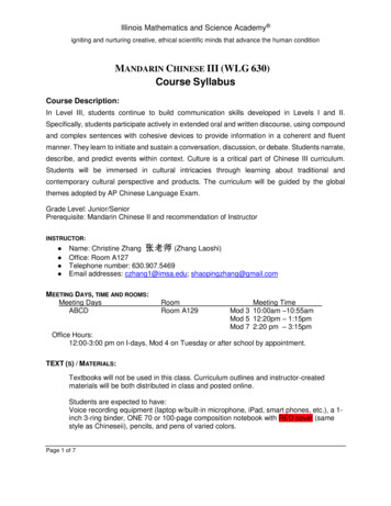
68S25LATERAL GUIDANCE SYSTEMFIGURE 10LATERAL GUIDANCE SYSTEMThe Century Flight Systems, Inc. Lateral Guidance System contains. Trackinterception angles a completely automatic, analog computer that directs theautopilot in both VOR and ILS navigation. The system contains a five position modeselector switch which mounts in the instrument panel are 45 and an automatic 15 crosswind correction capabilities is provided. The complete capture, intercept andtracking sequence is accomplished automatically without monitoring or multipleswitching.15
68S25Figure 11Figure 12OMNI MODEWhen in the OMNI MODE position, the system is coupledto the Radio Omni Bearing Indicator. By setting the D.G.Course Indicator to match the Omni Course selection, allheadings are then controlled by the Omni radio signals.A full deflection on the Omni Indicator (10 or more offselected radial) will produce a 45 interception angle.Inside the 10 area, the system will automaticallycompute the location and closure rate to direct a smooth,tangential intercept without overshoot and arrive over theradial with crosswind correction established. The samedynamic intercept is accomplished whether 2 miles ormaximum reception distance from station. Below 2 miles,the aircraft bank limitations will allow a slight overshootwhen making maximum angle interception.NAV MODEThe NAV Mode is designed to extend the coupler utilityby making operation practical under the adverseconditions of unsteady or erratic VOR Signals. Severalfactors such as terrain, distance, bent courses, etc.,produce short term needle deflections which can causeexcessive roll motion when in the OMNI Mode. The NAVMode incorporates an extended time delay in thecomputer circuit which reduces reaction to these shortterm needle deflections. Close in OMNI approach workrequires the proportioned dynamic response as providedin the OMNI Mode. Therefore the NAV Mode should notbe used for close in work.16
68S25HEADING MODEWhen in the HDG mode, the Century III Autopilot willfunction in the same manner as described in section I ofthis manual.Figure 13Figure 14LOCALIZER (Normal) MODEIn the LOC NORM mode, the system automaticallyadjusts its sensitivity to accommodate the 2½ full needlesignal instead of the 10 as found in Omni navigation .As the Localizer beam which is only ¼ as wide as theOmni, additional damping circuits are also switched in toproduce the same smooth intercept track as described forthe Omni. Intercept angles of 45 are still automatic withfull signal deflection and tangential intercepts withautomatic crosswind correction are accomplished beyondthe Outer Marker. As with the Omni mode, the CourseSelection D.G. must be set to correspond with the desiredmagnetic track.LOCALIZER (Reverse) MODEAll Century Flight Systems, Inc. Lateral GuidanceSystems are equipped with the Localizer Reverse featureto permit automatic backcourse approaches and to trackoutbound on the Front Course prior to procedure turn.The features of LOC-N
Century III represents a new design concept in which the conventional follow up, or control position fe