Transcription
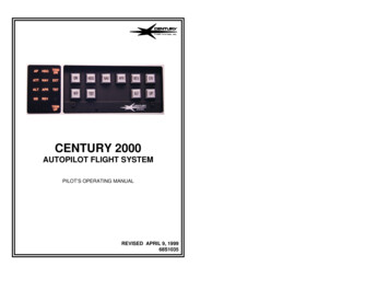
CENTURY 2000AUTOPILOT FLIGHT SYSTEMPILOT’S OPERATING MANUALREVISED APRIL 9, 199968S1035
FACTORY SERVICE CENTERSCentury Flight Systems, Inc. has established Factoryowned and operated Customer Service Center.Thepersonnel operating this Center are dedicated to providingCustomer Satisfaction with our products.Besides providing technical consultation, Service Centerpersonnel also provide competent repairs and sparessupport to our dealers as well as direct customer in or outof warranty repair service. The location of our FactoryService Center is:LOG OF REVISIONS06-01-87Altitude Preselect AdditionPages i, ii, ReplacedPages 75, 76, 77, 78 Added06-01-87Page 9, 10 Replaced07-19-94Preflight Test SequencePage 7a, 7b, 7c, and 7d added.02-07-97Directional Gyro Section added.Book reformatted and pages renumbered.12-19-97Add to NOTE on pages 7, 9, and 11.04-09-99Changes to Yaw Damper write-up onpage 22.Municipal Airport, Mineral Wells, TexasProduct SupportTelephone: (940) 325-2517If any time you need service at the Center please call forand arrange for an appointment. This way, we canminimize shop repair time.iii
FORWARDFEATURES.Autopilot ON-OFF.Master Disconnect/Trim Interrupt.13.67.Preflight Test Sequence (“A” Mod.Preflight Test Sequence (“A” Mod. Trim Prompt 1113Lateral Operating Modes.13.Heading Systems .Selected Intercept Angle .16Approach.17.Review of Interlocks and Failure Warnings21Yaw Damper Systems.DIRECTIONAL GYRO .C2000 FLIGHT DIRECTOR/STEERING HORIZONCENTURY 2000 OPERATING TECHNIQUESHSI VOR NAVIGATION.HSI VOR APPROACH .HSI GS ARMING & CAPTURE.HSI LOCALIZER BACK COURSE .DG VOR NAVIGATION .DG LOCALIZER APPROACH.WARRANTY .iii182325272932.555763707375
FORWARDThe Century Flight Systems, Inc. Century 2000 Autopilot is an advancedGeneral Aviation Flight Control System utilizing “State of the Art”electronic techniques.In this handbook we have detailed the features, functions and generaloperating instructions of the Century 2000 System.May we suggest that you do two things:1. Read this handbook and your Airplane Flight ManualSupplement.The handbook presents general operatingprocedures. Each aircraft installation has an Airplane FlightManual Supplement or Autopilot Handbook that contains FAAapproved flight procedures and operating limitations in thatparticular model aircraft. The appropriate AFM Supplement is adocument which must be aboard U.S. Registered Aircraft with theautopilot installed.2. Spend some VFR time with the equipment to become familiarwith its operation so that you may have the full benefit of itscapabilities.NOTEThe Century 2000 Autopilot is a modular design. It may be installed andoperated as a roll axis only autopilot, roll and pitch axis, or a roll, pitch,and yaw axis. The asterisk symbol (*) appearing before certain sectionsof this manual indicates instructions for those systems having the pitchexpansion installed. Operators of the roll only Century 2000 shoulddisregard the sections, paragraphs and sentences marked by asterisk.THE CENTURY 2000 3-AXIS IFCS21
FEATURESThe Century 2000 AutopilotCENTURY OPERATING CONTROLSThe MODE PROGRAMMER push-button switches are backlighted anddimming is provided by the control panel light dimmer switch.This autopilot only version uses a standard artificial horizon incombination with a directional gyro (DG) or an NSD-360A, NSD-1000Horizontal Situation Indicator (HSI). A Century Flight Systems, Inc. YawDamper (Y/D) may be incorporated with the Century 2000 when a Y/D iscertified for your plane.An outstanding feature of the Century 2000 is that it has a rate basedinner loop for short term dynamics. This means that rate information isderived from the horizon so that motion about the roll and pitch axis isprogrammed to occur at a rate appropriate to the activity. Examples ofcontrolled rate motion are as follows:ROLL AXIS:Heading Command - Roll at 5 per second diminishing near banklimit.Navigation Soft Mode - Roll at 2.5 degrees per second to reducedbank limit (8 ).The MODE ANNUNCIATOR light intensity is controlled automatically by aself-contained ambient light level sensor; this feature provides optimumMode Annunciator light level for all cockpit conditions. The Century 2000Autopilot is activated with the Aircraft Master switch and operates in alow power state until the autopilot operation is desired. Mode selection ismade by pushing the desired mode switch on the Mode Programmer. Theselected mode will be illuminated on the Mode Annunciator.Gust Disturbances - Resisted by certificated servo velocity.*PITCH AXIS:Command Attitude - 0.7 per second attitude change.Gust Recovery - Maximum rate consistent with passenger comfort.Maximum System Capability - 2.4 per second .*A separate Trim Master switch is located on the Control Panel. Autotrimfunction is activated by the Autopilot Engage switch.43
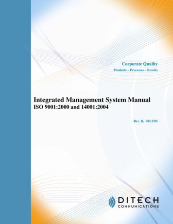
AUTOPILOT ON-OFF Autopilot engage is accomplished by pressingthe momentary ON switch on the left side of theProgrammer. The Autopilot will engage in theHDG mode. If the system is pitch expanded, theATT mode will also be present when engagedand the autopilot will synchronize to theexisting aircraft pitch attitude.*MASTER DISCONNECT/TRIM INTERRUPTONOFFIn HDG mode the aircraft will track the heading selected on the DG or HSI.In NAV, APR, or REV modes the aircraft will intercept and track anyproperly programmed radio-defined course. Instructions for proper radiosetup in these modes are included in this manual.* In ATT mode the autopilot will synchronize to the aircraft pitch attitudeupon engagement.* In ALT mode the aircraft will synchronize to the indicated altitudepresent at the time of engagement.The autopilot may be disengaged by pressingthe momentary OFF switch on the programmer,* by pressing the AP OFF switch on the controlwheel trim switch; * by pressing the MasterDisconnect/Trim Interrupt switch, if present onthe control wheel; or by interrupting power atthe Aircraft Master switch.Disengagementcauses the AP annunciator to flash for 5seconds.Many Century 2000 autopilots incorporate an additional switch on thecontrol wheel (usually a red button). Pressing this button will disconnectthe Century 2000, the Yaw Damper (if installed), and will interrupt theoperation of the Trim System. Release of the button will restore power tothe Trim System. However, the Autopilot will return to the HDG and ATTmode and will require re-engagement in order to resume automatic flight.*AUTOTRIM - The Century 2000 autopilot is equipped with automatic pitchtrim. When the Trim Master switch is on, Autotrim is activated byengaging the autopilot.*The Autotrim system is fail safe in design.system is verified by the preflight test.WHEEL SWITCH CONFIGURATIONSVARY WITH AIRCRAFT MODEL.*MANUAL ELECTRIC TRIM - With the Aircraft and Trim Master switcheson, a manually operated electric trim function is activated by the controlwheel trim switch. This switch serves a dual function:*1. Disengage the Autopilot.2. Activate manual electric trim.*Moving the red portion of the trim switch forward or aft will causeautopilot disengagement. Moving both parts of the trim switch forward oraft simultaneously will disengage the autopilot and cause the trim to runup or down.56The integrity of the trim
PREFLIGHT TEST SEQUENCECENTURY 2000 PREFLIGHT PROCEDURESFOR NO MOD. CENTURY 2000NOTEDuring system functional check the system must be provided adequateD.C. voltage (12.0 VDC or 24 VDC min.) and instrument air (4.2 in. Hg.Min.). It is recommended that the engine be operated to provide thenecessary power and that the aircraft be positioned in a level attitude,during the functional check. Due to the weight of the elevator in certainmodels of aircraft, steps 4 and 5 may not move the control wheel. Toverify correct direction of commands, support elevators to remove weightand continue steps.AUTOPILOT/AUTOTRIM - To be performed before the first flight of eachday.*1. Trim Master switch - ON.2. Engage autopilot.3. Move the heading bug left and right of the lubber line. Observe thatthe control wheel moves in the direction of the heading bugdisplacement.*4. Press the DN switch - verify that the control wheel moves in the downdirection. Verify that after approximately a 3 second delay, the trimmoves in the down direction.*5. Press the UP switch - verify that the control wheel moves in the updirection. Verify that after approximately a 3 second delay, the trimmoves in the up direction.6. Grasp control wheel and override roll and *pitch servo actuators toassure override capability.7. Hold control yoke and disengage autopilot by activating the AP OFFswitch on the control wheel or by the programmer off switch.8. Check controls through full travel in roll and pitch to assure completeautopilot disengagement.9. With autopilot OFF, press TST switch.All annunciators shallilluminate.*10.After “GS” and “ALT” annunciators extinguish release TST SWITCH;only “HDG”, “ATT”, and “TST” remain illuminated.*11.Press DN switch, HDG, and ATT annunciators remain illuminated, TSTmay momentarily flicker and then remains illuminated.*12.Press UP switch, HDG, and ATT annunciators remain illuminated, TSTmay momentarily flicker and then remains illuminated.*13. Momentarily press TST switch. HDG and ATT annunciators remainilluminated, TST annunciator flashes.*14. Press and hold DN switch. TST annunciator extinguishes7*15.Press and hold the UP switch. TST annunciator extinguishes.*16.Momentarily press and release TST switch.HDG and ATTannunciators remain illuminated, TST annunciator extinguishes.*COMMAND TRIM SYSTEM - To be performed before the firstflight of each day.1. Using the control wheel trim switch, verify normal trim up and downoperation.2. Move red portion of trim switch forward and aft. Observe that the trimsystem does not operate.3. Release the red bar on the control wheel trim switch. Move the blackportion fore and aft. Observe that the trim system does not operate.This completes the test sequences.CAUTIONAny failure of the above procedures indicates that a failure exists in thesystem and the system shall not be operated until the failure has beenlocated and corrected.CAUTIONCheck the elevator trim setting before takeoff.8
PREFLIGHT TEST SEQUENCECENTURY 2000 PREFLIGHT PROCEDURESFOR “A” MOD. CENTURY 2000NOTEDuring system functional check the system must be provided adequateD.C. voltage (12.0 VDC or 24 VDC min.) and instrument air (4.2 in. Hg.Min.). It is recommended that the engine be operated to provide thenecessary power and that the aircraft be positioned in a level attitude,during the functional check. Due to the weight of the elevator in certainmodels of aircraft, steps 4 and 5 may not move the control wheel. Toverify correct direction of commands, support elevators to remove weightand continue steps.AUTOPILOT/AUTOTRIM - To be performed before the first flight of eachday.*1. Trim Master Switch - ON.2. Engage Autopilot.3. Move the heading bug left and right of the lubber line. Observe thatthe control wheel moves in the direction of the heading bugdisplacement.*4. Press the DN Switch - verify that the control wheel moves in the downdirection. Verify that after approximately a 3 second delay, the trimmoves in the down direction.*5. Press the UP Switch - verify that the control wheel moves in the updirection. Verify that after approximately a 3 second delay, the trimmoves in the up direction.6. Grasp control wheel and override roll and pitch servo actuators toassure override capability.7. Hold control yoke and disengage autopilot by activating the AP OFFSwitch on the control wheel or by the programmer off switch.8. Check controls through full travel in roll and pitch to assure completeautopilot disengagement.9. With autopilot OFF, press and hold TST switch. All available modeannunciators shall illuminate for 3 seconds then extinguish and theAP shall flash as long as the TST switch is held.*10. Release the TST switch. Only HDG, ATT and TST shall be illuminated.*11.Press and hold the DN switch. The TST annunciator may momentarilyflicker but should remain illuminated.HDG and ATT shallremain on. Release the DN switch.9*12.Press and hold the UP switch. The TST annunciator may momentarilyflicker but should remain illuminated. HDG and ATT shall remain on.Release the UP switch.*13.Momentarily press and hold the TST switch. The AP and TSTannunciators shall flash and the HDG and ATT shall stay illuminated.Release the TST switch. The HDG and ATT shall remain on the TSTannunciator shall remain flashing.*14.Press and hold the DN switch. The TST annunciator shall extinguish.HDG and ATT shall remain on. Release the DN switch.*COMMAND TRIM SYSTEM - To be performed before the first flight ofeach day.1. Using the control wheel trim switch, verify normal trim up and downoperation.2. Move red portion of trim switch forward and aft. Observe that the trimsystem does not operate.3. Release the red bar on the control wheel trim switch. Move the blackportion fore and aft. Observe that the trim system does not operate.CAUTIONAny failure of the above procedures indicates that a failure exists in thesystem and the system shall not be operated until the failure has beenlocated and corrected.CAUTIONCheck the elevator trim setting before takeoff.10
PREFLIGHT TEST SEQUENCECENTURY 2000 PREFLIGHT PROCEDURESFOR “A” MOD. CENTURY 2000TWO AXIS TRIM PROMPTERNOTEDuring system functional check the system must be provided adequateD.C. voltage (12.0 VDC or 24 VDC min.) and instrument air (4.2 in. Hg.Min.). It is recommended that the engine be operated to provide thenecessary power and that the aircraft be positioned in a level attitude,during the functional check. Due to the weight of the elevator in certainmodels of aircraft, steps 4 and 5 may not move the control wheel. Toverify correct direction of commands, support elevators to remove weightand continue steps.1. Engage autopilot.2. Move the heading bug left and right of the lubber line. Observe thatthe control wheel moves in the direction of the heading bugdisplacement.3. Press the DN Switch - Verify the control wheel moves in theDOWN direction.** Verify that after approximately a 3 second delay, the Trim DNPrompt flashes.4. Press the UP Switch - Verify the control wheel moves in theUP direction.** Verify that after approximately a 3 second delay the Trim UP Promptflashes.5. Grasp the control wheel and override roll and pitch servo’s to assureoverride capability.6. Hold control wheel and disengage autopilot. Check controls throughfull travel in all axis to assure complete autopilot disengagement.7. With autopilot OFF, press and hold TST switch. All available modeannunciators shall illuminate for 3 seconds then extinguish and theAP shall flash as long as the TST switch is held.8. Release the TST switch. Only HDG, ATT and TST shall be illuminated.9. Press and hold the DN switch. The TST annunciator may momentarilyflicker but should remain illuminated. HDG and ATT shall remain on.Release the DN switch.10. Press and hold the UP switch. The TST annunciator may momentarilyflicker but should remain illuminated.HDG and ATTshall remain on. Release the UP switch.1111. Momentarily press and hold the TST switch. The AP and TSTannunciators shall flash and the HDG and ATT shall stay illuminated.Release the TST switch. The HDG and ATT shall remain on the TSTannunciator shall remain flashing.12. Press and hold the DN switch. The TST annunciator shall extinguish.HDG and ATT shall remain on. Release the DN switch.13. Press and hold the UP switch. The TST annunciator shall extinguish.HDG and ATT shall remain on. Release the UP switch.14. Momentarily press the TST switch. HDG and ATT shall remainilluminated, TST annunciator shall extinguish.**The control wheel may have to be assisted to move up and/or down.CAUTIONAny failure of the above procedures indicates that a failure exists in thesystem and the system shall not be operated until the failure has beenlocated and corrected.CAUTIONCheck the elevator trim setting before takeoff.12
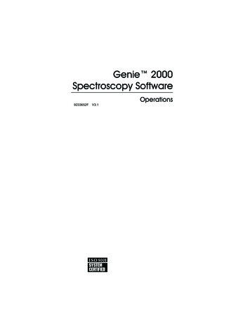
PREFLIGHT TEST SEQUENCECENTURY 2000 PREFLIGHT PROCEDURES FOR“A” MOD. CENTURY 2000 SINGLE AXISNOTEDuring system functional check the system must be provided adequate D.C.voltage (12.0 VDC or 24 VDC min.) and instrument air (4.2 in. Hg. Min.). It isrecommended that the engine be operated to provide the necessary power andthat the aircraft be positioned in a level attitude, during the functional check.NAVIGATION - In NAV mode the autopilot has anautomatic 45 degree VOR-LOC intercept angle.Selected angle intercepts are available when thesystem is equipped with NSD-360A, NSD-1000 orother .5.Engage autopilot.Move the heading bug left and right of the lubberline. Observe that thecontrol wheel moves in the direction of the heading bug displacement.Grasp the control wheel and override roll servo to assure overridecapability.Hold control wheel and disengage autopilot. Check control through fulltravel to assure complete autopilot disengagement.With autopilot OFF, press and hold TST switch. All available modeannunciators shall illuminate.CAUTIONAny failure of the above procedures indicates that a failure exists in thesystem and the system shall not be operated until the failure has beenlocated and corrected.CAUTIONCheck the elevator trim setting before takeoff.When executing an intercept, the rate at which the aircraft is closing uponthe selected radio-defined course is determined by the computer and atthe proper time an on-course turn is initiated. thirty-five seconds after theon-course turn the computer will reduce its bank limits to 13 degrees.After 70 seconds the bank limits will be reduced to 8 degrees to produce a‘soft’ navigation mode when tracking a VOR signal. The system willremain in ‘soft’ mode during station passage. However, if a new coursewhich requires re-intercept is selected, the ‘soft’ mode will unlock and theintercept sequence will reoccur.LATERAL OPERATING MODESNOTESHEADING - In HDG mode the autopilot willcapture and hold the heading selected on theDG or HSI. HDG annunciator will illuminate.APHDGHDGThe NAV mode should be used when executing a holding pattern on thelocalizer to prevent automatic glideslope coupling.When radio receiver is tuned to a localizer frequency, the coupler willoperate with localizer (APR) dynamics in the NAV mode.ONHDGNAVAPRREVDNOFFTSTFDYDALTUP1314
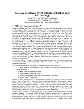
HEADING SYSTEMSSELECTED INTERCEPT ANGLEIn systems equipped with a DG the autopilot heading bug must be set tomatch the selected VOR/LOC course when in NAV, APR, or REV modes.For loran or GPS tracking, set the heading bug to the “desired bearing”information.In systems equipped with a NSD-360A, NSD1000 or other HSI, a selected intercept anglefunction is available while operating in the NAV,APR, and REV modes.HDGNAVIn systems equipped with and NSD-360A, NSD-1000 or other HSIinstrument, the heading bug is disabled when in the NAV, APR, or REVmodes. In these modes the azimuth information to the autopilot isprovided by the radio course pointer.Selected angle intercepts areperforming the following steps:HDGAPRHDGREVinitiatedby1. While operating in the HDG mode, set thecourse pointer to the desired radial .2. Set the heading bug on the NSD to thedesired intercept heading.3. Press the HDG and NAV, HDG and APR orHDG and REV mode buttons PNAVNOTESIn systems equipped with an NSD-360A, NSD-1000 or other HSI always setthe radio course pointer to the Front Course Inbound Heading whenoperating in the APR or REV modes.In systems equipped with a DG, during an instrument approach, theheading bug must be set to match course for the segment of theapproach being flown when using the NAV, APR, or REV modes.See section on operating techniques for additional operating instructionsfor the NSD-360A, NSD-1000 and the DG.15Both HDG and the selected lateral mode will now il
The Century Flight Systems, Inc. Century 2000 Autopilot is an advanced General Aviation Flight Control System