Transcription
Discrete CosineTransform for 8x8Blocks with CUDAAnton Obukhovaobukhov@nvidia.comAlexander Kharlamovakharlamov@nvidia.comSeptember 2013
Document Change HistoryVersionDateResponsibleReason for Change0.824.03.2008Alexander KharlamovInitial release0.925.03.2008Anton ObukhovAdded algorithm-specific parts, fixed some issues1.017.10.2008Anton ObukhovRevised document structureSeptember 20132
AbstractIn this whitepaper the Discrete Cosine Transform (DCT) is discussed. The two-dimensionalvariation of the transform that operates on 8x8 blocks (DCT8x8) is widely used in image andvideo coding because it exhibits high signal decorrelation rates and can be easilyimplemented on the majority of contemporary computing architectures. The key feature ofthe DCT8x8 is that any pair of 8x8 blocks can be processed independently. This makespossible fully parallel implementation of DCT8x8 by definition. Most of CPU-basedimplementations of DCT8x8 are firmly adjusted for operating using fixed point arithmeticbut still appear to be rather costly as soon as blocks are processed in the sequential order bythe single ALU. Performing DCT8x8 computation on GPU using NVIDIA CUDAtechnology gives significant performance boost even compared to a modern CPU. Theproposed approach is accompanied with the sample code “DCT8x8” in the NVIDIACUDA SDK.September 20133
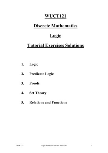
1. IntroductionThe Discrete Cosine Transform (DCT) is a Fourier-like transform, which was first proposedby Ahmed et al. (1974). While the Fourier Transform represents a signal as the mixture ofsines and cosines, the Cosine Transform performs only the cosine-series expansion. Thepurpose of DCT is to perform decorrelation of the input signal and to present the output inthe frequency domain. The DCT is known for its high “energy compaction” property,meaning that the transformed signal can be easily analyzed using few low-frequencycomponents. It turns out to be that the DCT is a reasonable balance of optimality of theinput decorrelation (approaching the Karhunen-Loève transform) and the computationalcomplexity. This fact made it widely used in digital signal processing.There are several types of DCT [2]. The most popular is two-dimensional symmetricvariation of the transform that operates on 8x8 blocks (DCT8x8) and its inverse. TheDCT8x8 is utilized in JPEG compression routines and has become a de-facto standard inimage and video coding algorithms and other DSP-related areas. The two-dimensional inputsignal is divided into the set of nonoverlapping 8x8 blocks and each block is processedindependently. This makes it possible to perform the block-wise transform in parallel, whichis the key feature of the DCT8x8.A lot of effort has been put into optimizing DCT routines on existing hardware. Most of theCPU implementations of DCT8x8 are well-optimized, which includes the transformseparability utilization on high-level and fixed point arithmetic, cache-targeted optimizationson low-level. On the other hand, the key feature of the DCT8x8 is not utilized in anyimplementation due to architecture limits. However, there is no limit for improvement.GPU acceleration of DCT8x8 computation has been possible since appearance of shaderlanguages. Nevertheless, this required a specific setup to utilize common graphics API suchas OpenGL or Direct3D. CUDA, on the other hand, provides a natural extension of Clanguage that allows a transparent implementation of GPU accelerated algorithms. Also,DCT8x8 greatly benefits from CUDA-specific features, such as shared memory and explicitsynchronization points.Figure 1. “Barbara” test image.September 20134
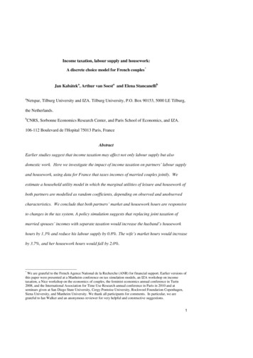
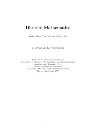
This paper illustrates the concept of highly-parallelized DCT8x8 implementation usingCUDA. Performing DCT8x8 computations on a GPU gives the significant performanceboost even compared to a modern CPU. The proposed approach is illustrated using thesample code that performs part of JPEG routine: forward DCT8x8, quantization of each8x8 block followed by the inverse DCT8x8. Finally, the comparison of execution speed isperformed for CPU and GPU implementations. The performance testing is done usingBarbara image from Marco Schmidt's standard test images database (Figure 1). The qualityassurance is done by means of PSNR, the objective visual quality metric.This paper is organized as follows. Section 2 gives some theoretical background of DCT andDCT8x8. The proposed implementations are described in Section 3. The evaluation of theproposed approaches and quality assurance issues are presented in Section 4. Optimizationissues can be found in Section 5, followed by the source code details in Section 6 and theconclusion in Section 7.2. DCT TheoryFormally, the discrete cosine transform is an invertible function F : N N orequivalently an invertible square N N matrix [1]. The formal definition for the DCT ofone-dimensional sequence of length N is given by the following formula:N 1C (u ) (u ) f ( x) cos (2 x 1)u 2Nx 0 , u 0,1, ., N 1(1)x 0,1, ., N 1(2)The inverse transformation is defined asN 1f ( x) (u)C(u) cos (2 x 1)u u 02N , The coefficients at the beginnings of formulae make the transform matrix orthogonal. Forboth equations (1) and (2) the coefficients are given by the following notation: u 1,u 0N2,u 0N(3)N 1As can be seen from (1), the substitution of u 0 yields C (0) (0) f ( x) , which is thex 0mean of the sample. By convention, this value is called the DC coefficient of the transformand the others are referred to as AC coefficients.For every value u 0,1, ., N 1 , transform coefficients correspond to a certain waveform.The first waveform renders a constant value, whereas all other waveforms ( u 1, 2, ., N 1 )produce a cosine function at increasing frequencies. The output of the transform for each uis the convolution of the input signal with the corresponding waveform.Figure 2 shows plots of waveforms mentioned above.September 20135
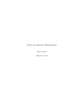
Figure 2. 1D basis functions for N 8.The two-dimensional DCT for a sample of size N N is defined as follows:N 1 N 1C (u, v) (u ) (v) f ( x, y) cos x 0 y 0 (2 x 1)u 2N (2 y 1)v cos 2N (4)The inverse of two-dimensional DCT for a sample of size N N :N 1 N 1f ( x, y ) (u) (v)C(u, v) cos u 0 v 0September 2013 (2 x 1)u 2N (2 y 1)v cos 2N (5)6
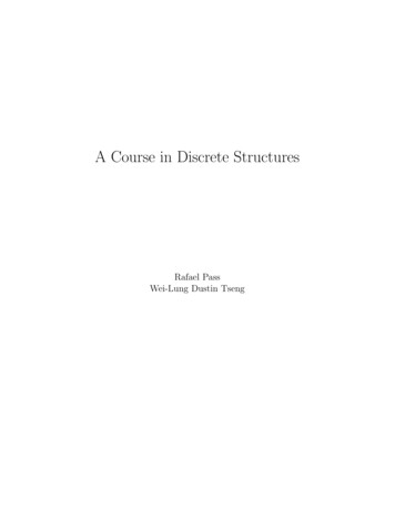
Figure 3. 2D basis functions for N 8.Separability is an important feature of 2D DCT, and allows expressing equation (4) in thefollowing form: N 1 (2 x 1)u (2 x 1)v C (u, v) (u ) (v)cos f(x,y)cos(6) 2N 2N y 0 x 0 This property yields the simple representation for basis functions of 2D transform; they canbe calculated by multiplication of vertically oriented 1D basis functions (shown in Figure 2for the case N 8 ) with their horizontal representations. The visualization of suchrepresentation is plotted on Figure 3. As can be seen from the plot, the basis functionsexhibit a progressive increase in frequency both in the vertical and horizontal directions.N 1 To perform the DCT of length N effectively the cosine values are usually pre-computedoffline. A 1D DCT of size N will require N vectors of N elements to store cosine values(matrix A ). 1D cosine transform can be then represented as a sequence of dot productsbetween the signal sample (vector x ) and cosine values vectors ( AT ), resulting intransformed vector AT x .A 2D approach performs DCT on input sample X by subsequently applying DCT to rowsand columns of the input signal, utilizing the separability property of the transform. Inmatrix notation this can be expressed using the following formula:C (u, v) AT XASeptember 2013(7)7
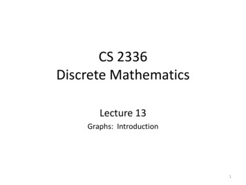
3. Implementation DetailsWith advent of CUDA technology it has become possible to perform high-level programparallelization. Generally, DCT8x8 is a high-level parallelizable algorithm and thus can beeasily programmed with CUDA.This section presents two different approaches to implementing DCT8x8 using CUDA. Thefirst one is used to demonstrate CUDA programming model benefits, while the secondallows creating really fast highly optimized kernels. The SDK sample includes 2 kernelsbased on the second approach: for the floating point data and for short integer data types(the routine is similar to that is used in LibJPEG).In order to avoid confusion some notations need to be introduced: Block of pixels of size 8x8 will be further referred to as simply block; A set of blocks will be called a macroblock. The number of blocks in a macroblockdenotes the size of a macroblock. The common size of a macroblock is 4 or 16blocks. The layout of blocks in a macroblock should be given before each usage; CUDA threads grouped into execution block will be referred to as CUDA-block.Implementing DCT by definitionThe implementation of DCT8x8 by definition is performed using (7). To convert input 8x8sample into the transform domain, two matrix multiplications need to be performed.This solution is never used in practice when calculating DCT8x8 on CPU because it exhibitshigh computational complexity relatively to some separable methods. Things are differentwith CUDA; the described approach maps nicely to CUDA programming model andarchitecture specificity.Image is split into a set of blocks as shown on Figure 4, left. Each CUDA-block runs 64threads that perform DCT for a single block. Every thread in a CUDA-block computes asingle DCT coefficient. All waveforms are pre-computed beforehand and stored in the arraylocated in constant memory. This array can be viewed as a two dimensional array containingvalues of basis functions A( x, u) one per column (shown in Figure 2).Two-dimensional DCT is performed in four steps (considering thread-level):1. A thread with coordinates (ThreadIdx.x, ThreadIdx.y) loads one pixel from a textureto shared memory. In order to make sure the whole block is loaded to the moment ,all threads pass synchronization point;2. The thread computes a dot product between two vectors: ThreadIdx.y column ofcosine coefficients (which is actually the row of AT with the same number) andThreadIdx.x column of the input block. To ensure all coefficients of AT X arecalculated, the synchronization must be passed;3. The thread computes ( AT X ) A in the same manner as in 2;September 20138
4. The whole block is copied from shared memory to the output in global memory.Each thread works with the single pixel.Note:The proposed implementation requires only two 8x8 blocks in shared memory and one8x8 block in constant memory. The CUDA and the CPU versions can be found in the firstkernel (dct8x8 kernel1.cu) and first reference (gold) functions (DCT8x8 gold.cpp).Barbara image with 8x8 blocks Barbara image split into Barbara image split into(1st kernel)macroblocks. Each macroblock macroblocks. Each macroblockcontains 8 blocks (2nd kernel)contains 16 blocks (shortkernel)Figure 4. Barbara image split with different grids.Traditional DCT ImplementationDCT is not usually computed by definition. In fact the most common practice is to optimizecomputation by avoiding redundant multiplications and utilizing the separability of 2D case.Such approach has been implemented on GPU in [4] and shows processing speed of 300 Hzfor 512x512 Barbara image.The proposed approach uses DCT8x8 separability on all levels of detail. An image is splitinto a number of macroblocks. To calculate the DCT coefficients for a single block (Figure4, left) only 8 threads are needed (the whole 1D 8-tap DCT is performed by a thread), so inorder to create enough workload for the GPU, the size of a macroblock must be multiple ofthe number of threads within the warp. In case of NVIDIA GeForce 8x series the numberof threads in a warp is 32, which maps to a macroblock of sizes 4x (Figure 4, center, right).Each thread performs DCT for the row and column corresponding to its ThreadIdx.xnumber inside the block with coordinates (ThreadIdx.y, ThreadIdx.z) inside the macroblock.The reduced computation of 8-point DCT is based on the approach from [3]. The majorityof low-level optimizations that are common in CPU implementations aren’t needed heresince floating point math is native to GPUs and MUL, ADD and MAD operations areexecuted with the same speed. The proposed implementation is optimized by the totalamount of described floating point operations. The floating point divisions by constants arereplaced with multiplications by reciprocals or arithmetic shifts.September 20139
The described approach takes into account the structure of matrix AT that exhibits highredundancy and symmetry of matrix elements. It can be presented in the following symbolicform (the axes of symmetry are drawn with dash line): 1 TA 8 1a1c1d1f1 f1 d1 cbce f e a b d bd eaef1 1 111 1 1de a bfbc e c e fba bf dc aa cd1 a b c ,1 d e f (8)where a, b, c, d , e, f stand for (9): a 2 cos 16 b 2 cos 8 3 c 2 cos 16 5 d 2 cos 16 3 e 2 cos 8 7 f 2 cos 16 (9)Thus, the 8-point DCT equation Y AT X can be decomposed in (10):11 X 0 X 7 Y 0 1 1 Y 2 b e e b X 1 X 6 1 Y 4 8 1 1 1 1 X 2 X 5 Y 6 e b b e X 3 X 4 (10) Y 1 a c d f X 0 X 7 Y 3 f a d X 6 X 1 1 c Y 5 f c X 2 X 5 8 d a ca X 4 X 3 Y 7 f dAs can be seen from (10), there is still some clear symmetry in the matrix corresponding toeven elements of vector Y , which can be properly utilized.Note:The proposed implementation requires single macroblock allocated in shared memory andfew floats in constant memory. The CUDA and the CPU versions can be found in thesecond kernel (dct8x8 kernel2.cu), short kernel (dct8x8 kernel short.cu) and secondreference (gold) functions (DCT8x8 gold.cpp).4. EvaluationAfter DCT8x8 is computed, it is possible to perform all sorts of analysis based on its values.In JPEG compression DCT coefficients are quantized to reduce the amount of informationSeptember 201310
that cannot be perceived by the human eye. The compression rate depends on the quantityof coefficients that are non-zero after quantization has been performed. Roughly speaking toachieve compression rate of 75 percent (of the initial size), 25 percent of least valuablecoefficients should be zero after quantization step.This sample is not dedicated to JPEG compression, however to illustrate the use of DCT8x8an additional step for quantizing DCT coefficients and running inverse DCT8x8 on them isperformed. The resulting image that contains blocking artifact due to quantization is storedto hard drive.The evaluation of the sample can be done in several ways: the speedup rate analysis andconsistency checking of CPU and CUDA implementations of the same approach. As for thefirst, each implementation outputs the pure processing timing to the console window. Thespeedup rate can be measured as the ratio of timings of reference CPU (Gold)implementation and of CUDA implementation. The consistency checking is the assurancethat both CPU and CUDA implementations of the same approach produce the same outputgiven the same input. The bitwise check of results may fail here because of possibledifferences in floating point operations sequences in both implementations or due todifferences in floating point units. Therefore the consistency checking is performed usingthe objective image similarity metric PSNR.We have chosen PSNR because it is commonly used to evaluate image degradation orreconstruction quality. PSNR stands for Peak Signal to Noise Ratio and is defined for twoimages I and K of size M N as:PSNR( I , K ) 20 log10MAX I(11)MSE( I , K )Where I is the original image, K is a reconstructed or noisy approximation, MAX I is themaximum pixel value in image I and MSE is a mean square error between I and K :MSE( I , K ) 1 1M NM 1 N 1 I (i, j) K (i, j)2(12)i 0 j 0PSNR is expressed in decibel scale and takes on positive infinity for identical images. Inimage reconstruction typical values for PSNR vary within the range [30,50] . PSNR of 50and higher calculated from two images that were processed on diverse devices with the samealgorithm says the results are practically identical.Orig.–Impl.Barbara 512x512Barbara 1Kx1KBarbara 2Kx2KBarbara 4Kx4KGold 132.77709234.61290036.81454539.721603CUDA 132.77702734.61290736.81454539.721588Gold 232.77705034.61288836.81454539.721588CUDA 232.77703934.61288536.81454539.721592Table 1. PSNR between Original and Processed images.September 201311
The consistency checking of CPU and CUDA implementations of both approaches toDCT8x8 implementation is performed in two steps:1. PSNR values between the original image and the processed (blocky) results arecalculated. It is natural to expect that these values should be similar for bothimplementations. Given Barbara image of size 512x512 as an input, the expectedPSNR values approximate to 32.777.2. PSNR between images compressed by CPU and CUDA implementations of thesame approach is calculated. Any values above 50 dB are considered as consistentresult, which yields that CUDA implementation works properly.GPU–CPUBarbara 512x512Barbara 1Kx1KBarbara 2Kx2KBarbara 4Kx4KImpl. 1.58.61366362.18804262.83418363.089985Impl. 2.63.90323366.19233766.54739468.100159Table 2. PSNR between images processed on diverse architectureswith the same algorithm.For Barbara test image the results obtained on step 1 are shown in the Table 1. Comparisonbetween images processed on CPU and GPU is given in Table 2.5. Optimization issuesThere are several ways to get rid of G8x architecture while developing CUDA kernel. Hereare some of the short paths: Eliminate bank conflicts while working with shared memory. This issue wasresolved by padding each row of the macroblock stored in shared memory with oneelement. The resulting amount of shared memory used per CUDA-block is(MACROBLOCK WIDTH 1) x MACROBLOCK HEIGHT. Suchconfiguration allows simultaneous accessing rows and columns without bankconflicts. This hack is also used in Transpose SDK sample. Access global memory in coalesced manner. In second kernel the copying fromglobal to shared memory is performed by the same threads that perform 8-tap DCT.However, this approach doesn’t work for short kernel (each element is 2 byteslong). It causes 2-way bank conflict (in shared memory) and uncoalesced globalmemory access. This issue can be resolved if only half of threads in each blockperform moving of 2 short elements as a single 4-byte element. Eliminate all other reasons of warp serialization (non-unified constant memoryaccess, etc.) Maximize GPU occupancy. The value can be calculated using OccupancyCalculator. Briefly, the value depends on the following parameters:oSeptember 2013Amount of shared memory usage. The more memory is used by CUDA block –the less amount of CTAs can be launched simultaneously.12
oNumber of registers used per-thread. The occupancy values close to 1.0 can bereached in case that each cuda thread uses not more than 10 registers perthread. Note that nvcc has several optimization options (refer nvcc guide).One can adjust maximum register count per thread using ptxas switch –maxrregcount N that forces the compiler to use not more than N registersper thread. This usually increases slow local storage usage, which candrastically degrade performance when no local storage had been used.There are still few ways to decrease registers usage: either by rewritingportions of the code directly in PTX assembler, or by manually declaring Nvariables and assigning all intermediate calculation results to them (thisapproach was partially adopted in 2nd and short kernels).oAmount of threads per block. This parameter often conflicts with sharedmemory usage. They have to be adjusted simultaneously.6. Source Code DetailsThe whole sample code is documented using Doxygen
8x8 block followed by the inverse DCT8x8. Finally, the comparison of execution speed is performed for CPU and GPU implementations. The performance testing is done using Barbara image from Marco Schmidt's standard test images database (Figure 1). The quality assurance is do