Transcription
A BestPracticesSteam TechnicalBriefSteam PressureReduction:Opportunitiesand Issues
BestPractices Technical BriefSteam Pressure Reduction:Opportunities and Issues IntroductionSteam generation systems are found in industry and in the commercial and institutional sectors. Some ofthese plants employ large watertube boilers to produce saturated steam at pressures of 250 pounds per squareinch (psig) or lower. They distribute steam for use in process applications, building heating, humidification,domestic hot water, sterilization autoclaves, and air makeup coils.Oversized boiler plants and steam distribution systems utilizing saturated steam are potential candidatesfor reducing the steam system operating pressure. Steam systems can have large excess capacity in boilers,valves, pumps, and piping. This can also be true for peak winter conditions.What is Steam Pressure Reduction?Steam pressure reduction is the lowering of the steam pressure at the boiler plant by means of the pressuresetting on the boiler plant master control.Steam pressure reduction affects mainly the high pressure part of the steam system. Within practical limits,pressure-reducing valves (PRVs) will adjust the pressure at lower levels to the previous set points. Thismeans that most of the savings benefits from pressure reduction occurs in the high pressure section of thesteam system. Summary1. Steam pressure reduction has the potential to save fuel consumed by a steam system. The amountof capital investment may be minimal for the appropriate application of this efficiency measure.The amount of fuel that can be saved varies with the design and maintenance of the existing system.2. The potential to effectively reduce steam pressure most commonly applies to oversized steam systemsin industry and institutions. These steam systems supply steam for process applications and buildingheating. They are often oversized for summer operation and the peak load period. The operator ofthe plant must judge whether a boiler plant is oversized.3. Before the steam plant owner attempts to reduce steam pressure, an assessment of the boiler plant andsteam system should be made. This should include an analysis of the average and peak steam loads inrelation to the plant capacity. Data on piping, insulation, and steam trap condition should be collected.Piping drawings should be used to map out critical steam loads and the test procedure.4. While energy savings can result from reducing steam pressure, there are a significant number of areaswhere steam pressure reduction can reduce the operational effectiveness of the steam system. Theseareas should be properly accounted for and understood.5. Steam pressure reduction should be tested to establish the critical minimum pressure at a steam loadthat is above average but below peak. This will also provide an estimate of savings.6. If, prior to reducing boiler steam pressure, the boiler is already having carryover issues, these shouldbe addressed before considering reducing the boiler steam pressure. Steam System Losses and Savings Through Pressure ReductionA List of Boiler and Steam System LossesIt is useful to summarize the typical causes of boiler and steam system losses. Most of these losses varywith steam pressure (and temperature) and can potentially be reduced by lowering the steam pressure atthe boiler.Steam Pressure Reduction: Opportunities and Issues
BestPractices Technical BriefSome of the main potential losses in a steam system are noted in Figure 1. Only the energy losses that can bereduced by lowering steam pressure will be discussed in this technical brief, and are listed below: Flash steam loss through high-pressurecondensate receiver vents Steam leaks from high-pressurecomponents (e.g. valves and piping) Combustion loss Boiler radiation and convection loss Boiler blowdown loss High-pressure steam piping heat loss Steam supplied to the deaerator High-pressure steam trap leakage The enthalpy savings effect.LossesWhen steam pressure is reduced at the boiler, it is only reduced on the high-pressure side of the system. PRVs,which lower the main steam pressure automatically, respond to maintain the pressure on the downstream sideof the valve at the set point, for example, 15 psig. Therefore, losses occurring downstream of the PRV or abackpressure steam turbine are not reduced by lowering the boiler pressure.The following example illustrates the potential savings from steam pressure reduction. In a steam systemoperating at an average steam load of 38,500 pounds per hour (lb/hr) with one watertube boiler supplyingsteam and another on standby, the operating pressure at the boiler was reduced from 130 psig to 80 psig.The average fuel input to the boiler plant before steam pressure reduction is 49.3 million British thermalunits per hour (MMBtu/hr). The plant is modeled using the boiler combustion efficiency as tested over a rangeof pressures, and with estimates of the size, length, and pressures of distribution and condensate return pipingfor purposes of calculating radiation losses. Typical losses from radiation and steam trap leakage based onactual surveys of other facilities are applied.Combustion LossDry flue gas loss as defined by the American Society of Mechanical Engineers (ASME) Power Test CodeFigure 1. Boiler and Steam System LossesDeaerator Vent LossRadiation Loss fromHigh Pressure (HP)Steam PipingHP Steam Leaksfrom HP, PRV’s andother componentsSteam to DeaeratorDeaeratorSteam to ProcessPRVSteam Trap LeaksHigh PressureFeedwaterPump Combustion LossHPSteamLoadsLPSteamLoadsSteam Trap LeaksLow PressureCondensateReceiversBoiler RadiationLossPumpsBOILERSFuel Inputto BoilersFlash SteamVent LossMainCondensateReturn TankBoiler Blowdown LossPump LostCondensateSteam Pressure Reduction: Opportunities and IssuesRadiation LossCond Pipingand TanksLostCondensateSteam LineCondensate Return LineLosses
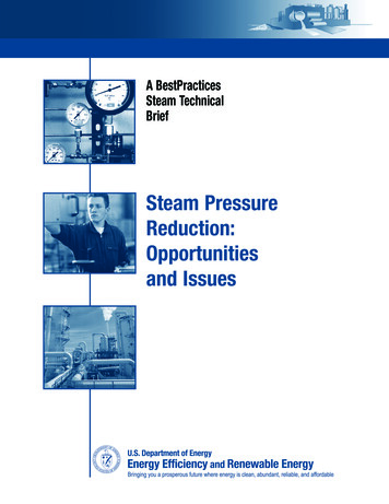
BestPractices Technical BriefFigure 2. Stack Temperature Vs. Boiler Pressure450400Stack Temperature F35030036236237538728028536230025020015010050Flue Gas Temperature Before (T1) and After (T2) Air Pre-HeaterAs tested for a Foster Wheeler 65,000 LB/HRWater-tubed boiler with combustion air pre-heater0Pressure PSIGT1T2varies directly in proportion to the boiler’s net stack temperature (the difference between the flue gas temperature and combustion air temperature). When boiler pressure is lowered, a lower stack temperature results.This, in turn, causes slightly improved combustion efficiency. If the boiler already has an economizer or airpreheater, the savings will be somewhat lower. The best way to establish the temperature reduction and savingsfor a given boiler is to conduct a combustion test at different pressures and constant load. Figure 2 shows therelationship between pressure and stack temperature for a test on a 65,000 lb/hr watertube boiler operating ata constant output of 38,500 lb/hr. As tested, the boiler stack temperature varies linearly with steam pressure.A savings of 0.4% to 0.8% of the fuel input can be expected from lower stack temperature.Boiler Radiation and Convection LossFor watertube boilers, radiation loss can be estimated using the American Boiler Manufacturers Association(ABMA) standard radiation loss chart. Radiation losses can also be calculated for any type of boiler, frombasic principles using measurements of the boiler surface temperature, area, and emissivity. In this example,the radiation loss is calculated from basic principles.The general formula for calculating radiation loss is:Radiation Loss (Btu/hr), HR 1.74 x 10⁻⁹ x e (T14 - T24)where 1.74 x 10⁻⁹ e T1 T2 Boltzmann’s constantSurface emissivity which depends on the specific material and condition (typically 0.9)The surface temperature as measured ( R)The ambient temperature as measured ( R)Heat transfer from the surface to the ambient air is increased by the flow of air across the surface. This iscalled convective heat transfer and must be added to the previously calculated radiation loss. For guidanceon calculating convective loss as a function of air velocity, refer to the basic heat transfer texts, for example,Thermal Insulation by John F. Malloy (see Reference list).For this example, when steam pressure was reduced from 130 psig to 80 psig, the actual temperature readingson the boiler surface showed an average reduction from 150 F to 140 F. Using the ABMA standard radiationloss chart, this would yield a savings of 0.2% of the fuel input.However, the ABMA chart does not apply to firetube boilers. Firetube boiler shell loss estimates shouldbe obtained by contacting the boiler manufacturers, or from basic principles and measurements of surfacetemperature.Steam Pressure Reduction: Opportunities and Issues
BestPractices Technical BriefBoiler Blowdown LossWhen boiler pressure is reduced, the blowdown loss is also reduced. If the energy from blowdown is beingrecovered through a blowdown heat recovery system, there will be no further savings by reducing the boilerpressure. If however, blowdown water is being drained and flash steam is being vented, savings will resultfrom steam pressure reduction. In the current example, reducing boiler pressure from 130 psig to 80 psigreduces the sensible heat in the boiler water from 328 Btu/lb to 294 Btu/lb. Assuming a blowdown rate of 4%,the savings is approximately 0.1% of initial fuel input.High Pressure Steam Piping Heat LossHeat loss from steam and condensate piping takes place in two stages. First, heat is conducted from hot steamthrough the walls and insulation surrounding the pipe to the outer surface. Then, heat is lost by radiation andconvection to the ambient air.A good way to make the calculations required to estimate the heat loss per foot of pipe is to use the BestPracticesSteam 3E-Plus, developed by the North American Insulation Manufacturers Association (NAIMA). The software isfree and is available at www.eere.energy.gov/industry/bestpractices/, www.naima.org, or www.pipeinsulation.org.Steam Leaks from High Pressure Valves, Piping, and Other ComponentsExternal steam leaks occur in piping, joints, valves, and other components for various reasons. In large steamsystems there are always some leaks. The degree of leakage depends on how well the system is maintained.Leaks in pipes may be caused by corrosion, erosion, water hammer, faulty design, or poor installation. Jointsof any type—welded, threaded, or flanged—can leak because the original connection was flawed. Valves leakexternally through their connections to piping or through the valve-stem packing or other paths. Pressure reliefvalves are notorious for leaking. Valves may also leak internally due to poor seats causing losses or pressureincreases in downstream equipment.The volume of steam leaking from a given source is difficult to measure. For purposes of including steamleakage as a loss factor in this report, the total leakage in each section of the steam system has been based onan equivalent round hole, 1/4 inch in diameter. Lowering the boiler pressure reduces the leakage rate in thehigh pressure part of the system only. In order to estimate the leakage through this hole and the savings fromlowering the boiler pressure, the following formula is used:Steam flow through a sharp-edged orifice: W 24.24 x Pa x D2 (Napier’s Equation)whereW leakage rate in lb/hrPa the absolute pressure drop across the orifice in pounds per square inch absolute (psia)D the diameter of the leaking orifice in inches.For example: Steam operating pressure 130 psigAbsolute pressure 130 14.7 144.7 psiaDiameter of orifice 0.25 inchesW 24.24 x 144.7 x (0.25)2 210.5 lb/hrAt lowered pressure, 80 psig, the new leakage rate is:W 24.24 x 94.7 x (0.25)2 137.7 lb/hrHigh Pressure Steam Trap LeakagePoor steam trap maintenance is a major cause of losses in steam systems. Many steam plant owners do nothave a scheduled maintenance program for steam traps.Lowering the main steam pressure is not a substitute for regular trap maintenance. However, based on the condition of the average steam distribution system, a reduction in boiler pressure can, for this example system, resultin savings of 0.6% of fuel input. The savings are realized only on the high pressure section of the steam system.Steam trap manufacturing and service companies provide routine testing services which can identify blocked,leaking, or “blow-through” defective traps. Normally, the service includes a calculation for each defective trap Steam Pressure Reduction: Opportunities and Issues
BestPractices Technical Briefof the amount of steam leaking through the orifice. Companies perform the estimates in different ways,employing considerable experience and judgment. The calculation is not as simple as one would make for drysteam blowing through an orifice from a high pressure (130 psig) to atmosphere. Other factors affecting thesteam loss that are taken into consideration include: A leak that is only a partial opening of the trap orifice, as compared to a “blow through” The flow co-efficient (Cv) of the steam trap Condensate may also be passing through the leaking orifice The possibility of a pressurized condensate return line The normal variation (reduction) of trap inlet pressure when variable process loads are involved.These factors act in various combinations to impose additional resistance to the flow of steam through theleaking trap orifice and result in a reduction in the theoretical steam loss as determined from Napier’s equationor other methods. In practice, the final result of the leak calculation for an individual trap may be between10% and 100% of the theoretical value.Nevertheless, a reduction in the main steam pressure will reduce the leakage in high pressure traps. A conservative estimate would be that the steam leak losses are proportional to the absolute pressure (in psia) of thehigh-pressure steam.For example, a high pressure, 3/4-inch trap with an orifice size of 1/8 inch and inlet pressure of 130 psig isestimated to be leaking 20 lb/hr of steam after deducting 66% of the theoretical leakage for the above factorslisted above. When estimating the leakage rate if the steam pressure at the inlet is lowered to 80 psig, the newleakage rate is approximately:[(80 14.7) psia / (130 14.7) psia] x 20 lb/hr 13.0 lb/hr Flash Steam Loss Through High-Pressure Condensate Receiver VentsLarge steam systems have multiple local condensate receivers which collect hot condensate and pump it backto the boiler plant. It is not uncommon to have multiple receivers located in various process departments orbuildings. Steam flashes as the condensate is lowered in pressure from the load pressure to the condensatesystem pressure.In the high-pressure section of the steam system, flash steam losses will be directly reduced by lowering thesteam pressure. When a steam trap passes condensate from the working pressure (130 psig) to the condensatesystem pressure (2 psig), the condensate contains excess energy above the liquid saturation level at the lowerpressure. This excess energy causes some of the liquid to flash into steam.The percentage of flash steam to total liquid can be calculated by using the following formula:Percent Flash Steam (hF1 - hF2) x 100%hFG2wherehF1 Enthalpy (sensible) of condensate at Pressure P1, inlet of steam traphF2 Enthalpy (sensible) of condensate at Pressure P2, outlet of steam traphFG2 Enthalpy (latent) of flash steam at P2For example:For : P1hF1hF2hFG2 130 psig and P2 2 psig328 Btu/lb187 Btu/lb966 Btu/lbPercent flash steam @ 130 psig (328 - 187) x 100 15%966Steam Pressure Reduction: Opportunities and Issues
BestPractices Technical BriefLower the Main Boiler Pressure to 80 psigPercent flash steam @ 80 psig (294 - 187) x 100 11%966From the example listed above, it can be observed that a reduction in boiler pressure will directly result in areduction in flash steam as condensate passes through steam traps from high to low pressure. This savingsapplies only to the high-pressure system. Also, note that this estimate is only valid if all of the flash steamgenerated in dropping from the high pressure to 2 psig is vented; therefore, this calculation can be anoverestimate of the potential savings. Another factor to consider is the possibility that flash losses are beingrecovered by means of a vent condenser. If this is the case, there is no savings associated with pressurereduction.Steam Supplied to the DeaeratorThe quantity of steam supplied to the deaerator is determined by the amount of energy required to heat amixture of hot condensate and cold makeup water to the saturation temperature at the operating pressure of thedeaerator, say 227 F at 5 psig. This steam represents a loss which can be minimized by good maintenance andmanagement practices.There will be a small reduction in steam supplied to the deaerator when the main pressure is reduced.Reductions in steam leaks, steam trap leaks, and flash vent losses all contribute to a reduction in the boilermakeup water rate and therefore to a reduction in the amount of steam supplied to the deaerator. Thereduction in deaerator steam can be calculated by doing a steam system mass and energy balance analysis.The Steam System Assessment Tool (SSAT) can be used for such analyses, and can be downloaded from theU.S. Department of Energy website at e.html.The Enthalpy Savings EffectTable 1 shows the enthalpy and temperature difference between steam produced at 130 psig and at 80 psig.The energy supplied to steam loads comes from the latent energy in the steam and not from the sensibleenergy. Once the steam condenses it is no longer part of the heat transfer process. When the steam is beingused at the pressure that the steam is being generated, it requires less steam (in pounds) to supply the requiredlatent energy at a lower pressure than at a higher pressure. In this case, 0.972 lb of steam at 80 psig suppliesthe same amount of energy as 1 lb of steam at 130 psig.The boiler supplies the same 866 Btu of latent energy to the load, regardless of the pressure. Otherwise,the energy supplied to the load will be insufficient.The reduction in enthalpy is a savings that occurs because of differences in the condensate condition as itreturns to the boiler plant from the load.Condensate loses energy due to flashing as it is reduced in pressure from the load to a much lower pressurethrough steam traps. It also loses energy and temperature from piping radiation loss as it is transferred fromTable 1. Enthalpies and Temperatures for Steam Lowered in Pressurefrom 130 psig (saturated) to 80 psig by Reducing Boiler PressurePressureMass (lb)130 psigCase A80 psig(reduced pressure)80 psigCase B110.0972 lbEnthalpySensible328 Btu294 Btu286 BtuLatent866 Btu891 Btu866 BtuTotal Enthalpy1194 Btu1185 Btu1152 Btu356 F324 F324 FSteam Temperature Steam Pressure Reduction: Opportunities and Issues
BestPractices Technical Briefthe load back to the boiler plant. Condensate from lower pressure steam loses less energy from flash thancondensate from high-pressure steam. The result is that at lower pressure, the boiler must supply less energyto the condensate to raise it from the feedwater condition to the saturation point. After this, the boiler stillsupplies the same 866 Btu needed to vaporize the feedwater.The examples below show this enthalpy reduction in simple terms (no deaerator is shown for simplification).The final result—a savings of 4.1%—is theoretical and only for purposes of illustration. An energy and massbalance analysis balance model, such as the SSAT, is a good tool to accurately estimate fuel savings fromsteam pressure reduction, including the enthalpy savings.130 psig CASE ABOILER328 Btu Sensible866 Btu Latent1194 Btu Total130 psigEnthalpy for 1 lb of SteamFlash Steamfrom Condensate1 lbFlash Steam 0.146 lbhF1 h F2 328 - 187 hFG2996HPSteamLoad 1
for a given boiler is to conduct a combustion test at different pressures and constant load. Figure 2 shows the relationship between pressure and stack temperature for a test on a 65,000 lb/hr watertube boiler operating at a constant output of 38,500 lb/hr. As tested, the boiler stack temperature varies linearly with steam pressure.