Transcription
World’s Leading Supplier of Soft BearingBalancing Machines & InstrumentsBalance Quality Requirementsof Rigid RotorsThe Practical Application of ISO 1940/1IRD Balancing Technical Paper 1
Balance Quality Requirements of Rigid RotorsThe Practical Application of ISO 1940/1ABSTRACTInternational Standard ISO 1940/1 is a widelyaccepted reference for selecting rigid rotorbalance quality. This paper is presented as atutorial and user's reference of the standard andits practical applications.USING THE STANDARDThe use of the standard involves the followingsteps:A simplified method is shown for determiningpermissible residual unbalance for various rotorclassifications. Emphasis is given to allocatingpermissible residual unbalance to appropriatecorrection planes for rotor configurations, suchas unsymmetrical, narrow and overhung rotors.Finally, a comparison of various balance qualitygrades is made with MIL-STD-167-1 and APIbalance limits.2. Use the Figure 1 (A or B) graph to determinethe permissible residual specific unbalancevalue, eper for the rotor's maximum operatingspeed and the selected "G number." Thenmultiply eper by rotor weight to obtain thepermissible residual unbalance, Uper.INTRODUCTIONThe International Standards Organization, ISO,published Standard 1940/1 "Balance QualityRequirements of Rigid Rotors," which has beenadopted by the American National StandardsInstitute, ANSI, as S2.19-1975, "Balance QualityRequirements of Rotating Rigid Bodies." It hasalso been adopted by BRITISH Standards as BS6861: Part 1 and by GERMAN Standards as VDI2060.Performing step 1 simply requires the user tofind the rotor type that most nearly describesthe one to be balanced.1. Select a balance quality grade "G number"from Table 1 based on rotor type.3. Allocate Uper to the balancing correctionplanes based on rotor configuration.Step 2 is more involved as it requires using thegraph in Figure 1 to find the permissible specificunbalance, followed by multiplying by rotorweight and then a constant to convert Uper toproper units (gram-millimeters or ounce-inches).This step can be simplified by using somesimple equations to calculate Uper directly.ISO 1940/1 requires an understanding ofbalancing and its terminology if the standard isto be understood and used properly. Thereader is directed to the paper's "BalanceTerminology" section for a summary of termsused in this paper.Step 3, allocating Uper, is often not performedbecause it is not easily understood.Therefore, the following pages provide asimplified method for step 2 and describe theprocedures for step 3.1
Table 1 Balance quality grades for various groups of representative rigid rotors(From ISO 1940/1)BalanceQualityGradeProduct of theRelationship(eper x v) (1) (2)mm/sRotor Types - General ExamplesG 4 0004 000Crankshaft/drives(3) of rigidly mounted slow marine diesel engines with uneven number of cylinders(4)G 1 6001 600Crankshaft/drives of rigidly mounted large two-cycle enginesG 630630Crankshaft/drives of rigidly mounted large four-cycle enginesCrankshaft/drives of elastically mounted marine diesel enginesG 250250Crankshaft/drives of rigidly mounted fast four-cylinder diesel engines(4)G 100100Crankshaft/drives of fast diesel engines with six or more cylinders(4)Complete engines (gasoline or diesel) for cars, trucks and locomotives(5)G 4040Car wheels, wheel rims, wheel sets, drive shaftsCrankshaft/drives of elastically mounted fast four-cycle engines with six or more cylinders(4)Crankshaft/drives of engines of cars, trucks and locomotivesG 1616Drive shafts (propeller shafts, cardan shafts) with special requirementsParts of crushing machinesParts of agricultural machineryIndividual components of engines (gasoline or diesel) for cars, trucks and locomotivesCrankshaft/drives of engines with six or more cylinders under special requirementsG 6.36.3Parts of process plant machinesMarine main turbine gears (merchant service)Centrifuge drumsPaper machinery rolls; print rollsFansAssembled aircraft gas turbine rotorsFlywheelsPump impellersMachine-tool and general machinery partsMedium and large electric armatures (of electric motors having at least 80 mm shaft height) withoutspecial requirementsSmall electric armatures, often mass produced, in vibration insensitive applications and/or withvibration-isolating mountingsIndividual components of engines under special requirementsG 2.52.5Gas and steam turbines, including marine main turbines (merchant service)Rigid turbo-generator rotorsComputer memory drums and discsTurbo-compressorsMachine-tool drivesMedium and large electric armatures with special requirementsSmall electric armatures not qualifying for one or both of the conditions specified for small electricarmatures of balance quality grade G 6.3Turbine-driven pumpsG11G 0.40.4Tape recorder and phonograph (gramophone) drivesGrinding-machine drivesSmall electric armatures with special requirementsSpindles, discs and armatures of precision grindersGyroscopes1) v 2πn/60 n/10, if n is measured in revolutions per minute and v in radians per second.2) For allocating the permissible residual unbalance to correction planes, refer to "AIIocation of Uper to correction planes."3) A crankshaft/drive is an assembly which includes a crankshaft, flywheel, clutch, pulley, vibration damper, rotating portion of connecting rod, etc.4) For the purposes of this part of ISO 1940/1, slow diesel engines are those with a piston velocity of less than 9 m/s; fast diesel engines are thosewith a piston velocity of greater than 9 m/s.5) In complete engines, the rotor mass comprises the sum of all masses belonging to the crankshaft/drive described in note 3 above.2
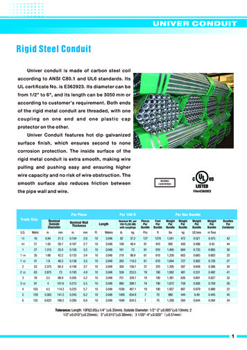
PERMISSIBLE RESIDUAL UNBALANCE eper in lb-in/lb of rotor weightorCENTER OF GRAVITY DISPLACEMENT, eper in inchesFigure 1-A Maximum permissible residual unbalance, eper(Imperial values adapted from ISO 1940/1)MAXIMUM SERVICE SPEED IN RPM3
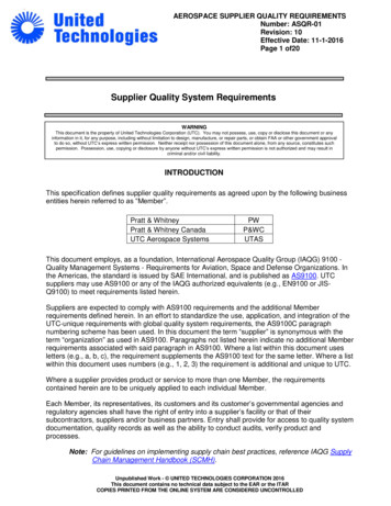
PERMISSIBLE RESIDUAL UNBALANCE, eper in g-mm/kg of rotor weightORCENTER OF GRAVITY DISPLACEMENT, eper in µmFigure 1-B Maximum permissible residual unbalance, eper(From ISO 1940/1)MAXIMUM SERVICE SPEED IN RPM4
BALANCE QUALITY GRADESTable 1 shows the balance quality grades for avariety of rotor types. The "G" number is theproduct of specific unbalance and the angularvelocity of the rotor at maximum operating speedand is a constant for rotors of the same type.ALLOCATION OF UperTO CORRECTION PLANESUper is the total permissible residual unbalanceand must be allocated to the balancing correctionplanes used based on rotor dimensions andconfiguration.G e x v constantFor rotors balanced in a single correction plane,all of the Uper applies to that correction plane.This is based on the fact that geometrically similarrotors running at the same speed will have similarstresses in the rotor and its bearings.For rotors balanced in two correction planes, Upermust be allocated to each correction plane basedon rotor configuration and dimensions.Balance quality grades are separated by a factorof 2.5. However, G numbers of intermediate valuemay be used to satisfy special requirements. Forexample, a standard pump impeller has asuggested balance quality grade of G 6.3. Specialconditions may require a better balance quality ofG 4.0 to satisfy installation in an area with lowstructure-borne noise limits.DETERMINING PERMISSIBLERESIDUAL UNBALANCE - UperUper eper x m(m rotor mass)Permissible residual unbalance is a function of Gnumber, rotor weight and maximum service speedof rotation. Instead of using the graph to look upthe "specific unbalance" value for a given Gnumber and service RPM and then multiplying byrotor weight (taking care to use proper units), Upercan be calculated by using one of the followingformulae:Uper (oz-in) 6.015 x G x W/N(W in Ib)Uper (g-in) 170.5 x G x W/N(W in Ib)Uper (g-mm) 9549 x G x W/N(W in kg)Figure 2 Symmetrical rotorsSYMMETRICAL ROTORSRules for symmetrical rotors. (See Figure 2.)1. Correction planes are between bearings.2. Distance "b" is greater than 1/3 "d."3. Correction planes are equidistant from thecenter of gravity.Uper left Uper right Uper/2When correction planes are NOT equidistant fromthe center of gravity, then -G Balance quality grade from Table 1Uper left Uper (hR/b)Uper right Uper (hL/b)W Rotor weightN Maximum service RPMThe Uper left or Uper right should not be less than30% or more than 70% Uper. If they are, thenuse rules for narrow rotors.A slide rule that calculates Uper is also availablefrom some balancing machine manufacturers.5
ROTORS WITH OUTBOARDCORRECTION PLANES3. Couple corrections are made 180 apart in theirrespective planes.4. The plane for static corrections may be a thirdplane or either of the planes used for couplecorrections.5. Allocate Uper as static and couple residualunbalance as follows:Uper static Uper/2 x d/2cUper couple Uper/2 x 3d/4bFigure 3 Rotor with outboard planesRules for rotors with correction planes outside thebearings. This is often referred to as a "dumbbell" rotor configuration. (See Figure 3)Both correction planes are outboard of thebearings.b dFigure 5 Narrow rotorsAdjust Uper by ratio of d/b. (Reduces Uper)Uper Uper (d/b)Permissible unbalance allocations for overhungand narrow rotors require that two planeunbalance corrections be divided into static andcouple unbalance equivalents. This can be donegraphically by plotting the two plane balancesolution vectors UL and UR as shown in Figure 6.Connect vectors UL and UR as shown. The vectorfrom the origin to the mid-point of vector CL-CR isone-half the rotor's static unbalance. Vectors CLand CR are the couple unbalance.Uper Adjusted valueWhen correction planes are not equidistant fromthe center of gravity, calculate Uper left and rightas follows:Uper left Uper (hR/b)Uper right Uper (hL/b)OVERHUNG AND NARROW ROTORSFigure 6 Static-couple graphical derivationFigure 4 Overhung rotorsRules for overhung and narrow rotors.(See Figures 4 and 5).1. Distance between correction planes is less than1/3 the distance between bearings. b 0.33 d.2. Assumes equal permissible dynamic bearingloads.6
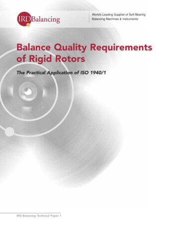
Figure 7 Comparision of API, ISO & MIL-STD-167-1 balance tolerancesCOMPARING API, ISO & MIL-STD-167-1BALANCE TOLERANCESUper Permissible residual unbalance FOR EACH CORRECTION PLANE in ounce inches. (oz-in)W Rotor Weight In Pounds. W 1000 lbs. for all examples shown.N Maximum Continuous Operating RPM.G ISO Balance Quality Grade Number, i.e. 6.3, 2.5, 1.0 etc.Fc 10% Journal Static Load Uper 56.347 x (Journal Static Load W/2)N2ISOUper G x 6.015 x W/2MIL-STD-167-1Uper W Uper APIN0.177 W(0 to 150 RPM)4000 W / N2(150 to 1000 RPM)4W/N(Above 1000 RPM)Total Rotor Weight4W/N(W Journal static Load)Fc 1.77 (RPM/1000)2 (oz-in)DATA TABULATIONMIL-STD-167Uper Centr.Noz-in ForceISO G 6.3Uper Centr.oz-in 83543495173467100133168201234[Centrifugal Force]ISO G 2.5Uper Centr.oz-in .853.866.479.792.8ISO G 1.0Uper Centr.oz-in 26.631.937.3APIUper Centr.oz-in Force13.34.02.01.00.60.50.40.30.3FC 10%W/2Uper Centr.oz-in Force0.5 10.826.00.6505050505050505050Copyright 1999 IRD BalancingMAXIMUM CONTINUOUS OPERATING RPMUseful Conversions1111inmmlbkg 25.4 mm.0394 in454 g2.2 lb1111milµmozg 25.4 µm.0394 mil28.35 g.0353 oz71 oz in 1 g mm 720 g mm.00139 oz in
BALANCE TERMINOLOGYSTANDARDS COMPARISONA frequent question is, "How do the ISO 1940/1quality grades compare with other balancingstandards, such as API and MIL-STD-167-1?"A comparison graph and data tabulation appearsin Figure 7. Three ISO grades (6.3, 2.5 and 1.0),MIL-STD-167-1 and API balance quality standardsare compared in tabular and graphical form.In addition, Uper was calculated for a constantcentrifugal force of 50 pounds (10% of staticjournal load). A symmetrical 1000 pound rotorwith the C.G. midway between bearings andcorrection planes was used. Static load at eachjournal is 500 pounds and centrifugal force wascalculated for each Uper.BALANCE QUALITY GRADE - GXXX - for rigidrotors, G, is the product of specific unbalance, e,and rotor maximum service angular velocity.Service angular velocity is service RPM expressedin radians per second.G e x v constantCENTER OF GRAVITY - the point in a body throughwhich the resultant of the weights of itscomponent particles passes for all orientations ofthe body with respect to a gravitational field C.G.CORRECTION (BALANCING) PLANE - planeperpendicular to the shaft axis of a rotor in whichcorrection for unbalance is made.To more clearly show the relationship, asummary of balance quality standards and theircorresponding centrifugal forces are shown inTable 2 as a percentage of journal static loadingfor 900, 1200, 1800 and 3600 RPM.Table 2 Centrifugal force as a percentof journal static load900 RPMBalanceQualityStd.1200 RPM1800 RPMUperUperUperF/L %F/L %F/L %oz-inoz-inoz-in3600 RPMUperoz-inF/L %ISO G6.3216.0%15.88.1%10.5 12.0%5.324.1%ISO .7%2.22.5%1.15.1%ISO 1.11.3%0.62.6%COUPLE UNBALANCE - that condition ofunbalance for which the central principal axisintersects the shaft axis at the center of gravity.CRITICAL SPEED - speed at which a systemresonance is excited. The resonance may be ofthe journal supports (rigid mode) or flexure of therotor (flexural mode).Uper Permissible residual unbalance for each correction planeF Centrifugal force due to residual unbalanceL Journal static loadL W/2W 1000 lbs.From the graph and Table 2, it is easy to seethat the API standard demands a low residualunbalance level and with a smaller unbalanceforce load on the rotor's bearings. However,the effort to achieve this result may not alwaysbe cost effective.Published balance tolerances provide everyonewith a common reference for communicatingbalance quality expectations, as well as whatthe provider promises. Proper interpretationand application of each is needed to realizesatisfaction for everyone.DYNAMIC UNBALANCE - that condition ofunbalance for which the central principal axis is notparallel to and does not intersect the shaft axis.8
Note: Dynamic unbalance is equivalent to twounbalance vectors in two specified planes whichcompletely represent the total unbalance of therotor.STATIC UNBALANCE - that condition of unbalancefor which the central principal axis is displacedonly parallel to the shaft axis.Note: Dynamic unbalance may also be resolvedinto static and couple unbalance vectors whosevector sum is also equal to the total unbalance ofthe rotor.SPECIFIC UNBALANCE - static unbalance Udivided by rotor mass m (i.e., mass eccentricity).Note: In the case of a rotor with two correctionplanes, specific unbalance may refer to theunbalance in one plane divided by rotor massallocated to that plane.FLEXIBLE ROTOR - a rotor that does not satisfy therigid rotor definition because of elastic deflection.REFERENCESPERMISSIBLE RESIDUAL UNBALANCE Uper - themaximum residual unbalance permitted for arotor or in a correction plane.1. ISO 1940/1, "Balance Quality Requirements ofRigid Rotors." International Organization forStandardization.Uper eper x mwhere m rotor mass2. ANSI S2. 19-1975, "Balance QualityRequirements of Rotating Rigid Bodies."American National Standards Institute.PRINCIPAL INERTIA AXIS - the coordinatedirections corresponding to the principal momentsof inertia. In balancing, the term principal inertiaaxis is used to designate the central principal axismost nearly coincident with the shaft axis of therotor.3. BS 6861: Part 1, "Balance Quality Requirementsof Rigid Rotors." British Standards Institution.4. VDI 2060, "Balance Quality Requirements ofRigid Rotors." German Standards Institution.RESIDUAL (FINAL) UNBALANCE - the unbalanceof any kind that remains after balancing.5. Standard Paragraphs, API Subcommittee onMechanical Equipment, Revision 19, September1991. American Petroleum Institute.RIGID ROTOR - a rotor is considered rigid if itsunbalance can be corrected in any two correctionplanes. After the correction, the residualunbalance does not change significantly at anyspeed up to the maximum service speed.6. MIL-STD-167-1 (SHIPS), 1 May 1974,"Mechanical Vibrations of ShipboardEquipment." Department of the Navy,Naval Ship Systems Command.ROTOR - a body capable of rotation whichgenerally has journals supported by bearings.7. "DYNAMIC BALANCING HANDBOOK,"October 1990, IRD Mechanalysis Inc.8. ISO 1925, “Balancing Vocabulary.”International Organization for Standardization.9
www.irdbalancing.comsales@irdbalancing.comUSA HeadquartersUSA: Louisville,KYUK: Chester1.888.473.2251 phone 44.1244.538170 phone1.502.238.1001 fax44.1244.528900 faxMEXICO: Mexico City CANADA: Quebec52.55.5689.8325 phone 1.450.724.4066 phone52.55.5689.8160 fax1.450.724.4077 faxIRD P/N E51267 Rev 2: Mar 2009
balancing and its terminology if the standard is to be understood and used properly. The reader is directed to the paper's "Balance Terminology" section for a summary of terms used in this paper. USING THE STANDARD The use of the standard involves the following steps: 1. Select a balance qual