Transcription
Developing Physical Solutions for InfoSphere Master DataManagement Server Advanced Edition v11MDM Workbench Development TutorialCopyright IBM 2013John Beaven – IBM, Hursley2013Page 1Copyright IBM 2013
ContentsOverviewMachine RequirementsSystem ConfigurationChanges in Version 11Some up-front TerminologySolution Overview344557Step 1 - Setting up the WorkspaceStep 2 – Configuring the Server ConnectionStep 3 - Creating the “Development Model”Step 4 - Creating the four new Entity Types8101214An introduction to containment structures16Step 5 - Creating “containment” relationshipsStep 6 – New Code Table & Type Code for RoomStep 7 - Extending the “Person” entity typeStep 8 - Enforcing ‘addPerson’ transaction validationStep 9 - Generating code from the modelStep 10 - Implementing the behaviour extensionStep 11 - Customizing the Code Table valuesStep 12 - Deploying the codeStep 13 - Deploying the metadata configurationStep 14 - Testing the Solution17202224272829323742Page 2Copyright IBM 2013
OverviewIn modern businesses, the volume of information being managed by an organization isincreasing whilst at the same time this information is becoming ever more critical to abusinesses success.If this information is not managed and controlled, there is the potential for companiesto make vital decisions based on incorrect data or become over whelmed by the scaleof the information.Master Data Management (MDM) solutions can provide a single, trusted view ofcritical business data and help organizations meet growth, revenue-generation andcost-reduction goals.The MDM Server provides such a solution with a comprehensive range of out of thebox services that help businesses manage and control their information.The MDM Workbench allows these services to be enhanced or extended to tailor thecapabilities for a specific deployment.This tutorial shows how the MDM Workbench can be used to design a model of theseadditional capabilities and how these can be deployed to the MDM Server.No prior experience of either the MDM Server or MDM Workbench is assumedThe instructions in this tutorial are broken down into two types of information. Thosesections marked with a 'textpad' icon contain background information that you canchoose to skip if if time is pressing and refer to later:(BACKGROUND!)Those sections marked with a 'user' icon contain the key steps that must be followedto complete the tutorial:(KEY STEPS!)Page 3Copyright IBM 2013
Machine RequirementsThe requirements for running MDM V11 are as follows: 8GB-12GB of memory50GB of dedicated disk space required for a typical installationTo set-up a machine for this tutorial, if MDM is not already installed, then it isrecommended to run a 'Typical Installation'. Instructions for this can be found byfollowing the link nstalling mdm workbench v11?lang enSystem ConfigurationThis tutorial assumes you have completed a typical installation of MDM V11including the software listed below: IBM Rational Application Developer for WebSphere Software Version 8.5.1IBM WebSphere Application Server Version 8.5.0.2IBM InfoSphere Master Data Management Workbench Version 11InfoSphere MDM Standard Edition or Advanced Edition Version 11IBM DB2 Version 10.1For a typical installation the default user ids and passwords are as follows: Page 4DB2 User ID: db2adminDB2 Password: db3AdminWebSphere User ID: mdmadminWebSphere Password: mdmadminCopyright IBM 2013
Changes in Version 11 (BACKGROUND!)What’s this section about? Discusses some changes since the last version of theworkbench. If you have not used the workbench before you can skip this section.One of the most apparent changes when using the latest version of the workbench isthat you no longer need to use the DEST utility to prepare the developmentenvironment. Unlike previous releases where an MDM Enterprise Archive (EAR) wasunpacked into the workspace, version 11 uses an Enterprise Bundle Archive (EBA)stored outside the workspace to provide the basis for development. The necessarydependencies on the EBA are established automatically when the workbench isinstalled. Modules developed in the workspace are combined into a CompositeBundle Archive (CBA) which can be deployed alongside the main server EBA tocustomize MDM.Some up-front Terminology (BACKGROUND!)What’s this section about? Provides an introduction to some of the core componentsthat make up a solution. Skip this section if required and refer to it as necessary.Entity Type – A physical entity in the MDM data model. As supplied the MDMServer supports a range of different Entity Types such as Person, Contract or Group.Additional Entity Types may be created in the Workbench to extend the data model.Attribute – A field defined for an Entity Type or Entity Type ExtensionEntity Type Extension – An extension to an out of the box Entity Type. Typicallythis mechanism is used to add additional attributes required by a solution that are notpresent in the out of the box data model. For example, if a Contract needed anadditional contract classification field, an Entity Type Extension could be defined toadd this. This should not be confused with a subtype, which is a separate concept.Creating an Entity Type Extension of Contract allows additional fields to be added torequests and responses that include instances of a Contract. The extension however isnot considered to be a separate type in its own right. Additional fields are included ina generic “extended block” that’s common to all Entity Type definitions.Code Table – A structure used to contain a set of String values that can be referred toby a Type Code. Conceptually similar to an enumeration in Java, these structures areused to hold well defined sets of values that don’t change often. For example, wecould create a Code Table to hold a set of colors (“Red”, “Green”, “Blue”, “Orange”)Once deployed each Code Table entry has both a “value” – the String representationPage 5Copyright IBM 2013
and a “type” – essentially the numerical database key. For example, (1, Red) or (2,Green)Type Code – A reference to an entry within a Code Table. When referencing a CodeTable, either the Code Table “Type” or “Value” may be specified. If both are present,they must match.Transaction – A service or operation that can be executed by a client on the MDMServer. For example, when adding a person to the database, users would invoke the“addPerson” transaction. XML is used to define a request which can be passed to theserver over a number of different interfaces (eg a WebService call)Behaviour Extension – Allows the default services provided by MDM to customizedby executing code before and/or after the core service runs. For example, we couldadd additional validation to ensure that specific constrains are met when performingan addContract transaction.Page 6Copyright IBM 2013
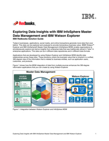
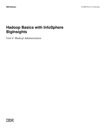
Solution Overview (BACKGROUND!)What’s this section about? Provides an outline of the solution that you will build inthis tutorial. If time is pressing, you can skip this and simply follow the instructions infurther sections below. Its recommended that you do at least review the modeldiagram in this section.For this tutorial, we have created a simplified model that consists of a range ofdifferent elements supported by the workbench. The tutorial shows how this model isdefined and converted into code. It demonstrates how this code can be modified tocustomize the solution and how this can then be deployed to and tested on a server.To keep things simple and allow you to focus on the mechanics involved, weminimized the amount of additional complexity that might be found in a real-worldscenario. During the course of this of this tutorial we will build following model:This model reflects a simplified asset tracking system used to manage machinery in afactory complex.Site – A new Entity Type introduced to hold information about a factory or plantlocation.Building – A new Entity Type used to hold details about a building at a SiteRoom – A new Entity Type used to hold details of a specific Room within a BuildingMachineAsset – A new Entity Type used to hold details of a physical machine assetwithin a room.Page 7Copyright IBM 2013
RoomType – A Code Table used to define the set of possible room classifications(“Office”, “PlantRoom”, “MeetingRoom”, “StoreRoom”)XPerson – MDM provides an “of the box” Entity Type called Person that holdsdetails of individuals that exist in the database. XPerson is an Entity Type Extensionof Person that defines an extra attribute not present in the standard data model. In thiscase, it’s a field that indicates if a person has been certified to operate heavymachinery.MinimumAgeCheck - Behaviour extension to ensure that all employees are over 16.Additional logic will run prior to the “addPerson” transaction to enforce this.Step 1 - Setting up the Workspace (KEY STEPS!)What’s this section about? The workspace will be prepared for development. Youmust follow these steps to complete the tutorial. Start RAD or RSA by running the application from the Desktop or Startmenu When the “Workspace Launcher” dialog appears, select a new folder tocontain the projects developed in this tutorial and click OKPage 8Copyright IBM 2013
Each time a brand new workspace is opened, the Configuring the WebSphereApplication Server dialog will appear. The next steps show how to use this to createa connection to the WebSphere server configured on the local machine: Page 9In the Configuring the WebSphere Application Server dialog, ensure the“Add WebSphere Application Server V8.5 configuration to theworkspace” option is checked.Specify the user id and password, for a typical installation the defaultsare “mdmadmin” and password “mdmadmin” under the authenticationsettings and click FinishOnce the workspace opens, close the Welcome screen by clicking on thecross on the Welcome tab.Copyright IBM 2013
You should now see an empty workspace as shown below:New “Development Projects”are created in here andcontain models and codedeveloped in the workspaceThe Problems tab shows detailsof any errorsResources being edited appearin the right hand panelThe Servers tab provides control overthe WebSphere application serverStep 2 – Configuring the Server Connection(KEY STEPS!)What’s this section about? The WebSphere server connection definition will beupdated to control how code is deployed from the workspace to the serverThe server connection created by the “Configuring the WebSphere ApplicationServer” dialog above needs some fine tuning. We need to change the settings so thatbinary code developed in the workspace is copied to the WAS server rather than beinglinked to it. The distinction may seem subtle, but the effect is to de-couple codedeveloped in the workspace with the code deployed on the server. The serverdeployment will remain valid and functional even if the workspace is deleted (if itwas linked to a workspace that was deleted, this would cause problems). Thefollowing steps show how to do this: Page 10Open the Servers view from the RSA main menu Window - Show View - ServersCopyright IBM 2013
Double click on the WebSphere Application Server v8.5 in Servers view toopen the configuration settings for the server connection. Under Publishing settings for WebSphere Application Server, ensure theRun server with resources on Server option is selected. Close the WebSphere Application Server v8.5 configuration Save the configuration settings when prompted by clicking YesThe workspace is now configured and you are ready to start developing code!Page 11Copyright IBM 2013
Step 3 - Creating the “Development Model”(KEY STEPS!)What’s this section about? A new Development project containing a developmentmodel (previously referred to as a Hub Model) will be created in the workspace. Youmust follow these steps to complete the tutorial. Open the “context menu” (right hand mouse button) in the Package Explorer orNavigator view (left hand portion of RAD window) Select New - Other from the menu In the New wizard, select Master Data Management - Development Projectwizard and click Next In the New Master Data Management Development Project window enter theproject name “FactoryAssetTracking”, the Base Java package name“com.factory.asset.tracking” and click NextPage 12Copyright IBM 2013
In the following panel enter “FactoryAssetTracking” for the Identifier(previously Hub Base Name) and db2admin for the Database schema name.Ensure that Add development project to composite is checked and that theComposite project is set to FactoryAssetTracking.cba. Click FinishHint: Once the project has been created you will be prompted to change to the MDMDevelopment perspective. You should click Yes to do this as certain menu options willnot be visible otherwise.When the wizard completes you will see that three projects have been created:FactoryAssetTracking – This is the “Development Project” that contains the solutionmodel file (module.mdmxmi) and eventually generated code.Page 13Copyright IBM 2013
FactoryAssetTracking.cba – This is the composite bundle archive that will grouptogether one or more development projects for subsequent deployment - the CBA isdeployed alongside the MDM EBA to customize MDM. Although you can have morethan one CBA, its recommended that you add further development projects to thesame CBA project.MDMSharedResources – This is similar to CustomerResources from previousversions of the MDM. It groups together content that’s solution wide rather thanproject specific (schema, SQL etc). Multiple projects contribute content. Open the module.mdmxmi file in the FactoryAssetTracking project and selectthe Model tab. This will open the empty development model in the right handpanel Step 4 - Creating the four new Entity Types (KEY STEPS!)What's this section about? In this section of the tutorial we will define the four newEntity Types that form the core of the solution. These are Site, Building, Room andMachineAsset. Initially these will be created without the relationships between themwhich will be added later. You must follow these steps to complete the tutorial. Open the context menu on the FactoryAssetTracking subfolder (shown below)and select New - Entity TypePage 14Copyright IBM 2013
In the right hand panel, change the name of the new Entity Type to Site Open the context menu on the Site Entity Type in the model tree view and selectNew - Attribute In the right hand panel, change the attribute name to name, the type to String,ensure that the Nullable field is not checked and that the Persistent field ischecked.Tip: The default string length of 250 characters is fine for all String types you createin this tutorial Repeat this process to create the Entity Types Building and Room, both ofwhich should have a single String attribute called name.Repeat this process one more time to create the Entity Type MachineAssetwhich should have attributes named name (String), serialNumber (String)and description (String).The Model should now look like this:Page 15Copyright IBM 2013
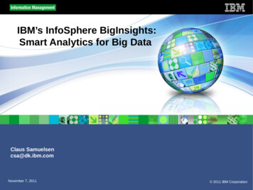
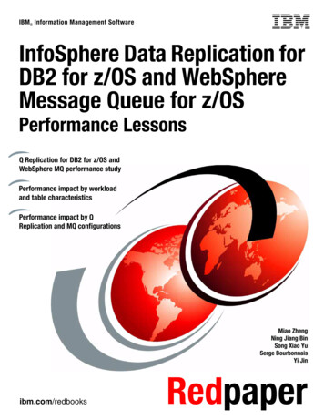
Tip: The workbench automatically adds primary key fields and basicCreate/Read/Update/Delete (CRUD) style transactions for each entity you create.For example you can add a new machine asset using the addMachineAssettransaction or query rooms by primary key using the getRoom transaction. Thesebasic CRUD transactions are available for all entity types developed in theworkbench.An introduction to containment structures (BACKGROUND!)What's this section about? This section provides a high level overview of whatcontainment relationships are and how they are represented in the developmentmodel. Skip this section if required and refer to it as necessary.In this model, a Site consists of a set of Buildings, a Building consists of a set ofRooms and a Room contains a set of MachineAssets. We can establish theserelationships as “containment” relationships where we say a “containing” entity suchas Building “contains” another “contained” entity such as Room.Exactly how this is modelled depends on the “cardinality” of the relationships andhere there are two key scenarios. Depending on whether the relationship is a “one-toone” or “one-to-many”, the workbench will create different model content when thecontainment is defined.“One to one” relationship:In this case, the containing entity has a single contained entity underneath it. This canbe captured in the model as a simple reference from the containing entity to thecontained entity as shown below:For example, if we assert that a Room only ever houses a single MachineAsset, wecould have a reference to a MachineAsset from Room. This is simplest case.Page 16Copyright IBM 2013
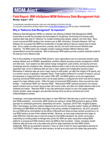
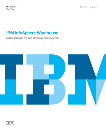
“One to Many” relationship:In many cases however, this is not realistic. For example a Room might well containmany different MachineAssets. Whilst it is possible to create multiple references froma ContainingEntity to different instances of the ContainedEntity, it is not possible tocreate an arbitrary number of such references. Using this approach we would have toknow in advance exactly how many references were required and give them allseparate names in the model – this is impractical and messy.The solution is to turn the problem around and have a reference from the containedentity to the containing entity as shown in the model below:For example a MachineAsset would have a reference to the Room in which it resides.By doing this, we can associate an arbitrary number of MachineAssets with a singleRoom.As mentioned above, the workbench creates simple CRUD transactions to support thedata model. For example, the “getRoom” transaction returns a specific Room given aprimary key. If you introduce a one-to-many containment relationship, you will see anadditional transaction gets added to the model under the contained entity. Thisadditional transaction provides a service to retrieve all instances of the containedentity that reference a given containing entity.For example, when the transaction getRoom(53) is invoked to retrieve the Room withprimary key 53, it will include in the response all those MachineAssets that reside inthis specific room – derived by the reference from MachineAsset to Room. In thiscase the transaction would be called “getMachineAssetByRoom” and would returnall those instances of MachineAsset that have a reference to Room 53.Step 5 - Creating “containment” relationships (KEY STEPS!)What's this section about? The “containment” relationships between these key EntityExtensions will be added to the model. You must follow these steps to complete thetutorial.To simplify this process, a wizard dialog is provided to automatically create therequired model components for a given containment structure. We will use thiswizard now to build up these relationships.First, we will create the containment of Building within a Site:Page 17Copyright IBM 2013
Open the context menu on the Site Entity Type and select New - Containment In the Containment Wizard dialog, enter a containment name buildingsEnsure the Allow multiple contained references option is checkedEnsure the Automatically create references and transactions option is checkedClick the Browse button and select the FactoryAssetTracking - FactoryAssetTracking - Building Entity Type. Click OK The Containment Wizard panel should then show a summary of the changes thatwill be made to the model. Check this matches those listed below and click FinishPage 18Copyright IBM 2013
Open the context menu on the Building Entity Type and repeat this process tocreate a new containment of Room named rooms. Open the context menu on the Room Entity Type and repeat this process to createa new containment of MachineAsset named machineAssets.Page 19Copyright IBM 2013
The model should now look like this:Step 6 – New Code Table & Type Code for Room (KEY STEPS!)What’s
This tutorial assumes you have completed a typical installation of MDM V11 including the software listed below: IBM Rational Application Developer for WebSphere Software Version 8.5.1 IBM WebSphere Application Server Version 8.5.0.2 IBM InfoSphere Master Data Management Workbench Version 11