Transcription
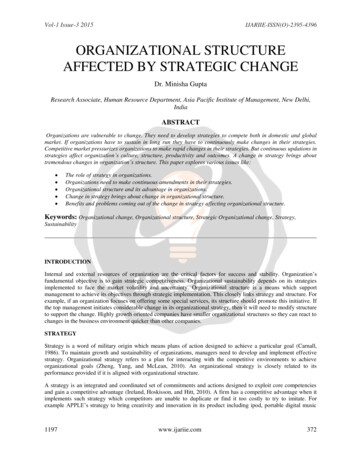
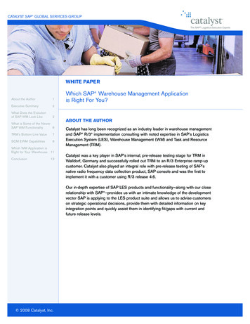
Decentralized Adaptive Control for Collaborative ManipulationPreston Culbertson1 and Mac Schwager2Abstract— This paper presents a design for a decentralizedadaptive controller that allows a team of agents to manipulatea common payload in R2 or R3 . The controller requires nocommunication between agents and requires no a priori knowledge of agent positions or payload properties. The agents cancontrol the payload to track a reference trajectory in linear andangular velocity with center-of-mass measurements, in angularvelocity using only local measurements and a common frame,and can stabilize its rotation with only local measurements. Thecontroller is designed via a Lyapunov-style analysis and hasproven stability and convergence. The controller is validated insimulation and experimentally.I. INTRODUCTIONCollaborative manipulation remains one of the most important problems in multi-agent systems. Using teams ofrobots to manipulate large or heavy payloads promisesmany advantages over single-agent manipulators, includingflexibility, scalability, and robustness to individual agentfailures. Applications for these systems include construction, manufacturing and assembly, search and rescue, anddebris removal. However, current strategies make restrictiveassumptions which prevent these systems from being usedin the field.A. ContributionThis paper presents a design for a decentralized adaptivecontroller that allows a team of agents to manipulate acommon payload in R2 or R3 . The controller has provenstability and requires no communication between agents andrequires no a priori knowledge of agent positions or payloadproperties.In this paper, we solve three collaborative manipulationproblems of varying difficulty, depending on the informationavailable to the agents. Firstly, we solve the problem ofgeneral manipulation, where the payload’s angular and linearvelocities are controlled. In the second problem, we aim totrack only a desired angular velocity for the body. We findthis can be achieved using only local measurements fromeach agent, assuming they share a common body-fixed frame.Further, without a common frame, the agents can still achievestabilization of the body’s angular rates. These strategiesapply to agents in R2 and R3 , and are robust to the additionor removal of agents.These results are consequences of a novel decentralizedadaptive control design strategy, which is introduced inthis paper for a class of nonlinear dynamical systems. TheThis work was supported in part by NSF Grant IIS-1646921. We aregrateful for this support.1 P. Culbertson is with the Department of Mechanical Engineering,Stanford University, Stanford, CA 94305 USA (e-mail: pculbertson@stanford.edu).2 M. Schwager is with the Department of Aeronautics and Astronautics,Stanford University (e-mail: r̂xyz,in̂yFig. 1: Four agents manipulate a common payload. The agents have noprior knowledge of the object’s mass or frictional properties, and cannotcommunicate with each other. Using the proposed decentralized adaptivecontrollers, they can control the body’s linear and angular velocities to tracka desired trajectory.controller is designed via a Lyapunov-style analysis, and hasproven convergence and stability properties.We experimentally demonstrate a team of omni-directionalground robots [1] manipulating a common payload in R2 ,and present a simulation of a team manipulating a payloadin R3 using Gazebo [2], an open-source dynamics engine.B. Prior WorkCollaborative manipulation has been extensively studied,beginning with a set of protocols for pushing rigid objectsin [3]. Various decentralized manipulation strategies havebeen proposed, including force sensing [4], potential fields[5], caging [6], consensus [7], and pseudo-inverse allocation[8]. In [9] the authors demonstrate automated transport andassembly of furniture with ground robots. In [10] the authorsdevelop and demonstrate a strategy for manipulating flexiblepayloads. Further, various recent papers have focused oncooperative manipulation with aerial vehicles, using bothcables [11] and rigid attachments [12], as well as pathplanning for cooperative lifting [13]. These algorithms, whilesuccessful, suffer from the significant drawback of requiringaccurate payload knowledge, including the locations of eachagent from the center of mass, as well as mass and frictionalproperties of the payload.To this end, some authors have sought to develop strategiesthat estimate or adapt to unknown payload dynamics. In [14]and [15] the authors develop a decentralized strategy forestimating payload parameters, and using these estimates formanipulation. However, these algorithms make extensive useof networking between agents, and do not perform estimationand control simultaneously.Previous work has also proposed applying adaptive control to manipulation tasks. In [16], the authors develop
a centralized adaptive controller to control the attitude ofa quadrotor. In [17], the authors develop a decentralizedadaptive controller that allows robotic arms to adapt to theirown dynamics, but consider the payload properties to beknown. Further, in [18], the authors develop a fully centralized adaptive controller for multiple manipulators moving anunknown payload.Our work applies results from Model Reference Adaptive Control (MRAC) [19]. Further, our work is related todecentralized adaptive control, wherein adaptive controllersare designed for interconnected systems, as in [20], [21].The remainder of the paper is structured as follows. InSection II, we formulate three collaborative manipulationtasks, and outline the assumptions required to accomplishthem. In Section III, we formulate the dynamics of themanipulation problems. Section IV presents a decentralizedadaptive controller design for a class of nonlinear dynamicalsystems that includes the dynamics described in Section III.In Section V, we assess our controller performance for amanipulation task in R3 using an open-source dynamicsengine. In Section VI, we present the experimental results ofour controller for a planar manipulation task using groundbased mobile robots.II. P ROBLEM S TATEMENTWe consider a team of n robots, Ri , i {1, ., n}, rigidlyattached to a rigid payload B, which has mass m and inertiamatrix I. Each agent has a body-fixed coordinate frame,r̂xyz,i , and there also exists a body-fixed frame b̂xyz in B.Each agent is attached at position ri , measured from theobject’s center of mass, and is capable of applying a forceFi and a torque Ti to the object. The body is located atposition p, and has a velocity vcm measured at its center ofmass, and angular velocity ω measured in Newtonian frameN . The body is also subject to a frictional force Ff (e.g.sliding friction or air resistance). A schematic of the systemis shown in Figure 1.Each agent has a low-level controller which can applythe desired forces Fi and torques Ti . The agents are alsoequipped with sensors to measure their linear velocity viand angular velocity ωi in N . Each agent also has accessto a reference signal and model trajectory, either via abroadcast from a ground station, or precomputed and storedonboard. The agents cannot communicate with each other orthe ground station, and have no a priori knowledge of thepayload’s mass or frictional properties.We now formulate three collaborative manipulation problems to be solved in this paper. The problems are orderedfrom most to least challenging, and each requires progressively less restrictive assumptions for its solution.Problem 1 (Collaborative Manipulation). Consider a teamofa rigid object B. Let x nT agents manipulatingTvcm ω Tdenote the object’s appended linear andangular velocities. Design a decentralized controller suchthat, given a reference velocity xm (t), the control lawguarantees stability and asymptotic tracking.To solve this problem, we make the following assumptions:Assumption 1 (Center-of-Mass Measurement). Each agenthas access to x(t), the linear and angular velocity of Bmeasured at its center of mass.Assumption 2 (Common Reference Frame). The agentsshare a common reference frame fixed in B (i.e. b̂xyz ), andknow the orientation between their frame r̂xyz,i and thisframe.While Assumption 1 appears restrictive, we discuss heremultiple options for its removal.One option is to place a sensor at the center of mass whichbroadcasts measurements to the agents. While this requiresprior knowledge of B, an adaptive algorithm still allows forthe solution of Problem 1 without measuring ri for eachagent, which can be prohibitively expensive for large teamsof agents.In addition, Assumption 1 is satisfied by each agentknowing its location ri with respect to the center of mass.This is due to w wi , and vcm can be calculated usingvcm vi ωi ri . We seek to remove this assumption infuture work by allowing measurements to be taken from anypoint on the body.We also note that Assumption 2 is only mildly restrictive.Assuming each agent has a compass or star tracker onboard,it may use this device to determine its orientation withrespect to the body frame.Further, we can consider additional manipulation problemsthat allow us to remove Assumptions 1 and 2.Problem 2 (Collaborative Rotation Control). Consider ateam of n agents manipulating a rigid object B. Design adecentralized controller such that, given a reference angularvelocity ωm (t), the control law guarantees stability andasymptotic tracking.We note that solving this problem does not require Assumption 1, since angular velocity is equal at all pointson a rigid body, and thus each agent may use its localmeasurement, ωi for control.We can further restrict the problem to also remove Assumption 2.Problem 3 (Collaborative Rotation Stabilization). Considera team of n agents manipulating a rigid object B. Design adecentralized control law that guarantees stability and drivesthe angular velocity to zero.While this problem is much more restricted than Problem1, it forms an important class of manipulation problemswhich includes the stabilization of orbital debris for activeremoval as proposed in [22].III. S YSTEM DYNAMICSIn this section, we formulate the dynamics of collaborativemanipulation tasks in R2 and R3 as nonlinear dynamicalFdvsystems. Throughout this discussion, we let dtdenote thetime derivative of vector v in the reference frame F.A. Planar ManipulationWe first consider a payload that is being manipulated inR2 by a team of agents. The linear dynamics are described
by F macm , where F is the resultant of all forces on thebody B, and acm is the acceleration of the payload’s centerof mass in N . For planar manipulation, we consider bothapplied forcesPnfrom the robots and frictional forces on thebody, F i 1 Fi Ff , where we model the frictionalforce Ff asFurther, the rotational dynamics of B are given byMB/Bcm Iα ω (Iω) where I is the inertia matrixof B, Ixx Ixy IxzI Ixy Iyy Iyz ,Ixz Iyz IzzFf µ0, sgn vcm µ1, vcm ,and MB/Bcm is the resultanton B about the centerPmomentnof mass. MB/Bcm Mf i 1 Ti ri Fi , where Mf µr ω denotes the rotational friction on B. Tvx vy vz wx wy wzLetx denotethesystemstate, andui TFxi Fyi Fzi Txi Tyi Tzidenote the inputfor agent i.Using the above equations, we can writePnẋ Ax i 1 Bi (ui Li f (x)),(2)where µ0, , µ1, are zeroth-order(viscous) frictional constants, and 1sgn(x) 0 1(sliding) and first-orderx 0x 0.x 0Additionally, we can write the linear acceleration asNdvcm (v̇x ωvy )b̂x (v̇y ωvx )b̂y .dtFurther, the rotational dynamics of B are given byMB/Bcm Jα, where MB/Bcm is the resultant of allmoments on B about its center of mass, J is B’s momentof inertia about b̂z , and α denotes B’s angular accelerationin N .We consider bothPapplied and frictional moments on B,nMB/Bcm Mf i 1 Ti ri Fi , where we model thefrictional moment about the center of mass asacm Mf ( µ0,r sgn ω µ1,r ω)b̂z ,for frictional constants µ0,r , µ1,r . TLet x vx vy ωdenote the system state and Tui Fxi Fyi Tidenote the system input for agenti.Using the equations above, we can writePnẋ Ax i 1 Bi (ui Li f (x)),(1)where where 1 0 µm I0mIA , Bi 1,0 µr I 1I Ri I 1 00010 11M 0Li B 1, M 0 1 0 0 1 0 ,0 Pn i1 0 1 0 0 0 0Iyz IyzIxz Ixy Izz Iyy ,Ixz Iyz Ixx IzzIxyP Ixz 0Ixy Ixy 0 Iyy IxxIyz Ixz and f (x) [ ωx vy ωx vz ωy vx ωy vz ωz vx ωz vy · · ·ωx2 ωy2 ωz2 ωx ωy ωx ωz ωy ωz ]T ,where I denotes the identity matrix, and Ri denotes thematrix form of the cross product of ri , 0 rzi ryi0 rxi .Ri rzi ryi rxi0 Note the dynamics (1) and (2) are of the same general form.0µ1, 1IV. D ECENTRALIZED A DAPTIVE C ONTROL , Bi 0 m0 ,A 0mµ1,rryrx100 mInthissection, we use techniques from Model Reference J µ0, J JAdaptiveControl (MRAC) to design decentralized adaptive000 11 1 mµ0, controllersfor a class of nonlinear systems. These controllers00 1 0 ,Li Bimµ0,rnrequirenocommunication between agents, no prior knowl000 0medge of system parameters, and have proven stability and Tasymptotic tracking. We then use these results to developand f (x) sgn(vx ) sgn(vy ) sgn(ω) ωvx ωvy.adaptive controllers for the manipulation problems describedB. General 3D Motionin Section II.We now consider a payload being manipulated in R3 . WeA. Decentralized Adaptive Controllernow only consider a first-order (viscous) friction model,Assume n agents are cooperating to control a nonlinearFf µ vcm .system, with system state x Rm . We assume the systemWhile we can also add zeroth- and higher-order terms to the is of the formnXfriction model, this is unnecessary when the object is freeẋ Ax Bi (ui Li fi (x)),(3)flying (e.g. in space or in the air), as it is not in contact withia sliding surface.We write the linear acceleration aswhere A Rm m , Bi Rm k , Li Rk qi are unknownNBconstant matrices, and fi (x) Rqi are a set of knowndvcmdvcmacm ω vcm .nonlinear basis functions which are continuous in x. Notedtdt µ1, m000 1m0
this is precisely the form of the planar manipulation (1) and3D manipulation (2) equations.The objective of the decentralized controllers is to chooseui Rk such that the system state x(t) tracks the trajectoryof a reference model xm (t) Rm , with LTI dynamics givenbyẋm Am xm Bm r(t),(4)where Am Rm m is stable, Bm Rm k , and r(t) Rkis a bounded reference signal. The reference model is chosenby the designer, and represents the desired dynamics for thesystem.Each agent i implements a controller of the formui Kxi x Kri r(t) L̂i fi (x),(5)where Kxi Rk m , Kri Rk k , L̂i Rk qi are controlgain matrices which are tuned online. Therefore, each agentseeks to choose control gains such that the closed-loopsystem tracks the reference model. This controller yields theclosed-loop dynamicsẋ (A nXBi Kxi )x (i 1nXBi Kri )r (i 1nXe i fi (x)),Bi Li 1(6)e i L̂i Li .where LThus, if we choose K xi , K ri , L i according toPnA i 1 Bi K xi Am ,Pn i 1 Bi Kri Bm ,Pn i 1 Bi (Li Li )fi (x) 0,ė ẋ ẋmnXe xi x Ke ri r Le i fi (x)),Bi (K(7)i 1e xi Kxi K is the feedback gain error andwhere KxieKri Kri K ri is the feedforward gain error.Since the error dynamics depend on the unknown matricesBi , we make a further assumption on the form of K ri ,namely:Assumption 3.K ri 1 1n Bi Bm ,forK ri0 orfollowing adaptation laws for the Γxi BTm PexT ,(8) Γri BTm PerT ,(9) Γ i BTm Pefi (x)T ,(10)where P PT 0 satisfies the Lyapunov equationPAm ATm P Qfor some Q QT 0, and Γxi , Γri , Γ i Rk k arepositive definite gain matrices.Theorem 1. If each agent implements the controller in (5),and the adaptation laws (8)-(10), then the system is stable inthe sense of Lyapunov, and achieves asymptotically perfecttracking.Proof. Consider the Lyapunov function candidatee xi , Ke ri , Le i ) eT Pe 1 P tr(Ke T K 1 Γ 1 Ke xiV (e, Kxi rixine T K 1 Γ 1 Ke ri Le T K 1 Γ 1 Le i ). Kriririiri iTaking the time derivative of V yields2P TeeV̇ eT Qe e PBm K 1ri (Kxi x Kri rne i fi (x)) 2 P tr(Ke T K 1 Γ 1 Ke xi Lxi rixine T K 1 Γ 1 Ke ri Le T K 1 Γ 1 Le i ). Kri riiriri iUsing the adaptation laws (8)-(10), we getthen the system dynamics match those of the referencemodel, and x(t) xm (t).We assume the desired gains K xi , K ri , L i exist, althoughthey are unknown a priori. Further, for the manipulationsystems considered here, the desired gains always exist whenthe designer chooses Bm 0.1Define e x xm as the tracking error. We use (4) and(6) to write the error dynamics Am e We now propose thecontrol gain matrices:e xi K̇xiKe ri K̇riKe i L̇iLK ri 0.This assumption is non-restrictive, and implies the desiredfeedforward control effort is evenly divided between theagents. Since all Bi are positive definite for the manipulationtasks considered in this paper (see Appendix), if Bm 0,then K ri 0 by design.1 We let M 0 denote that matrix M is positive definite, and M 0denote M is negative definite.V̇ eT Qe.(11)Thus, since V 0 and V̇ 0, the system is stable in thee xi , Ke ri , Le i are bounded becausesense of Lyapunov, and e, KV is nonincreasing. By definition, r(t) is bounded, and sinceAm is a stable matrix, the reference model is BIBO stable,so xm is also bounded. Since e, xm bounded, we also havex bounded from the definition of e, and ui bounded using(5) and the fact that fi are continuous in x (and thus boundedfor bounded x). Therefore, all signals in the closed-loop arebounded. Further, from (7) we have ė bounded.We can write the second derivative of V ,V̈ 2eT Qė,which is bounded since e, ė bounded. Thus, we invokeBarbalat’s Lemma [23] to conclude that V̇ 0 with t, andthus e 0.We note the controller (5) and adaptive laws (8)-(10) donot depend on n, the number of agents. Further, the controlleris robust to the addition or removal of agents, since this isequivalent to merely restarting the controller with differentn, and initial gains Kxi , Kri , Li .We also notice that the controller and adaptation lawsrequire only information available to each agent (specificallyKxi , Kri , e, r, f (x)), without requiring information fromany other agent. Thus, this is a decentralized adaptive controller that does not require explicit communication betweenrobots.
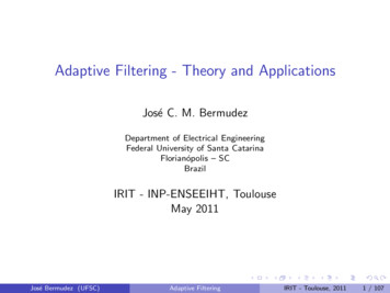
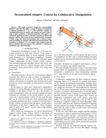
e xi , Ke ri , Le i,Further, since (11) does not depend on KV̇ 0 does not imply the parameter errors go to zeroasymptotically. An additional condition, persistent excitation(PE), must be satisfied for this to occur [19]. Thus, thecontrol gains Kxi , Kri , Li are not suitable for performingparameter estimation.·10 2600Proof. It is apparent that the dynamics of both systems inR2 (1) and R3 (2) are of the form in (3), with Bi whichsatisfy Assumption 3 by definition (see Appendix). Thisresult follows from Theorem 1.We now motivate Assumptions 1-2 for the solution ofProblem 1.Assumption 1 is necessary because the controller (5)and adaptation law (8) require a measurement of x, whichrequires a velocity measurement from the center of mass.Further, the dynamics in (1), (2) implicitly assume thevelocities are measured in a body-fixed frame. Thus, theagents must have access to this frame to achieve tracking.Corollary 2 (Controller for Rotation Control). If a team ofagents have a shared body-fixed frame b̂xyz , and implementcontrollers of the form (5) with adaptation laws of the form(8)-(10), then they can solve Problem 2, namely for x ω,lim x(t) xm 0.t Proof. It is again apparent that the rotational dynamics ofthe systems are of the form (3). This result again followsfrom Theorem 1.If the agents only apply torques Ti to the object, noneof the dynamics depend on, vcm . Further, since angularvelocity is equal on all points of a rigid body, each agent canmeasure x(t) locally, which allows us to relax Assumption1. However, solving Problem 2 still requires Assumption 2,since the agents require a common frame in which to expressthe reference signal r.Corollary 3 (Controller for Rotation Stabilization). If a teamof agents implement a decentralized controller of the form(5) with adaptation laws of the form (8)-(10), they can solveProblem 3, namelylim x(t) 0.t Proof. Suppose r(t) 0. Since this reference signal is equalin all frames, the agents can implement the proposed adaptivecontroller without requiring Assumption 2. This result againfollows from Theorem 1.50100·10 2150ω y [rad/s]vz [m/s]200ω z [rad/s]xm420 2050100150200t [sec](a) Simulated Trajectory for General R3 Manipulation·10 26V(t)lim x(t) xm 0.xm 2Corollary 1 (Controller for General Manipulation). If a teamof agents implement a decentralized controller of the form(5), and use adaptation laws of the form T(8)-(10), Tthey canωTsolve Problem 1, namely for for x vcm,t ω x [rad/s]vy [m/s]26B. Decentralized Adaptive ManipulationWe now apply the results from Section IV-A to themanipulation problems formulated in Section II. We showour controller design solves these problems, and motivateAssumptions 1-2.vx [m/s]4420050100150200t [sec](b) Lyapunov Function for General R3 ManipulationFig. 2: Simulation results for n 6 agents manipulating a common payloadin R3 . The agents aim to control the payload’s angular and linear velocities.(a): Simulated state trajectory, and reference trajectory. (b): SimulatedLyapunov function V for the manipulation task. The plotted function hasbeen shifted by a constant value.ParameterValuemIxxIyyIzzr1r2r3r4r5r62.6e4 (kg)4.47e6 (kg m2 )4.47e6 (kg m2 )1.40e5 (kg m2 )(0, 0, 20.4) (m)(6.9, 0, 0) (m)(-6.9, 0, 0) (m)(0, 6.9, 0) (m)(0, -6.9, 0) (m)(0, 0, -20.4) (m)TABLE I: Simulation ParametersV. S IMULATION R ESULTSTo validate our algorithm, we simulated its performancefor Problems 1-3. The simulation consisted of a team ofn 6 satellites rigidly attached to a large, free-floatingpayload (i.e. a rocket body). The mass properties of thepayload were based on a Delta IV first stage rocket, andthe model parameters are given in Table I.While the adaptation laws (8)-(10) are continuous derivatives, we used a forward-difference method to approximatethe derivative for a discrete-time implementation. Additionally, we modified the adaptation laws by adding σmodification and a deadzone to improve their robustness andtransient performance. These techniques are well studied, andoutlined in [24].Figure 2(a) shows the simulated trajectory for a groupof agents performing general manipulation on the body B.A sinusoidal reference signal of multiple frequencies was
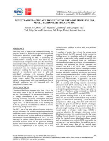
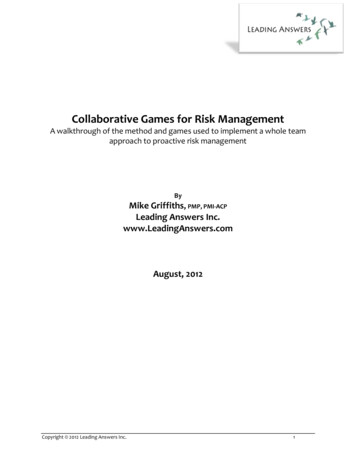
ωxωyωzxm0.50 0.5050100150(a) Simulated Trajectory forωzxm0050100150200t [sec]Rotation ControlFig. 4: Simulated trajectory for n 6 agents controlling the rotation of acommon payload. At tdrop 45s, 4 agents are deactivated.42050100150200t [sec](b) Lyapunov Function for R3 Rotation ControlFig. 3: Simulation results for n 6 agents controlling the rotation of apayload in R3 . Only local measurements are used for control. (a): Simulatedstate trajectory, and reference trajectory. (b): Simulated Lyapunov functionV for the manipulation task The plotted function has been shifted by aconstant value.commanded in vx , vy , and ωx , while zero velocities werecommanded in the other states. The agents were able tomeasure the velocities at the center of mass, and had acommon body-fixed frame. It is apparent that the systemachieves asymptotic tracking, as shown in Corollary 1.Further, Figure 2(b) plots the Lyapunov function V (t) forthe simulation. For ease of computation, the function V (t)was evaluated by integrating V̇ , given by (11). Since V 9 0with t, the plot is offset by a constant amount. From the plot,we can see V̇ 0.Figure 3(a) shows the simulated trajectories for a group ofagents controlling the rotation of body B. The agents onlyapplied torques Ti to the body, and used local measurementsfor control. The figure indicates that asymptotic tracking isachieved. Further, from Figure 3(b), we again see that V̇ 0.As discussed in Section IV-B, the control strategy is robustto the addition/removal of agents during manipulation. Figure4 shows a simulation in which the agents attempt to controlthe rotation of body B, where 4 of the n 6 agents areturned off at tdrop 45s. The controllers are able to respondto this change, and still achieve asymptotic tracking.Further, Figure 5 plots the simulated trajectories of a groupof agents attempting to stabilize body B to zero angularvelocity. The body was given an initial angular velocity of[3, 3, 3] (rad/s) about its principal axes. The agents did nothave access to central measurements or a common referenceframe. Despite these constraints, the agents were still able tostabilize the body’s rotation.VI. E XPERIMENTAL R ESULTSWe also evaluated the control strategy experimentally,using a team of ground-based mobile robots. A schematic ofthe experimental setup is shown in Figure 6. The robots haveomnidirectional wheels, and use an onboard PID controllerω(t) [rad/s]V(t)ωy 0.520040ωx0.5t [sec]R3tdrop1ω(t) [rad/s]ω(t) [rad/s]1ωxωyωzxm20 2 40204060t [sec]Fig. 5: Simulated trajectory for n 6 agents attempting to stabilize therotation of a body in R3 . Only local measurements are used for control,and agents do not have a common reference frame.to provide the desired force Fi and torque Ti by generatingmotor speeds. The robots received velocity measurementsvia an OptiTrack motion capture system. All controller codewas executed onboard each robot. All communication wasperformed using ROS over a wireless network. The payloadhad a mass of m 16.5 kg, and inertia J 2.46 kg m2 .Figure 7(a) shows the results of the controllers whencommanded a square wave in vx , and zero velocity in vyor ω. The test consists of 50 trials of 60 seconds each. Eachrobot was initialized with randomly scaled control gains, andhad no unique prior knowledge of the object parametersor its position on the object. While the robots initially donot respond to the velocity command, their controllers adaptonline to allow the payload to begin moving, and eventuallyto track the reference signal.Figure 7(b) shows the average value of the Lyapunovfunction V (t) for the trials, as well as the maximum andminimum value at each timestep. The variance in the functionvalues is likely due to unmodelled effects, including networklatency, discretization error, and static friction. It is apparentthat V̇ is decreasing in magnitude, but does not fully reach 0by the end of the trial, indicating the parameters can evolvefurther to achieve better tracking.Figure 7(c) shows the results of the controllers whentracking a reference signal generated by a human user. Thereference signal was generated in real time using a joystickoperated by the human user, and broadcast over the wirelessnetwork.Again, we can see the controllers initially do not respondto velocity commands, but begin to track the commands astheir controllers adapt. Good tracking is achieved for arbitrary signals in vx , vy , while moderate tracking is achievedin ω. The difficulty in rotational control is likely due tostatic rotational friction, as well as control gains which wereinitialized to values far from their true values.
where A Rf f , C Rg f , D Rg g , if A, D 0 thenM 0.b̂xyzProof. Using the results in [25], we writedet(M λI) det(A λI) det(D λI)BcmThus, the eigenvalues of M are equal to the union of thoseof A and D, which have positive real parts. Thus, M 0,as needed.r̂xyz,iFig. 6: Four ground robots manipulate a common payload. The agentsachieve asymptotic tracking in linear and angular velocity without priorknowledge or explict communication with other agents. All computation isperformed onboard.VII. C ONCLUSION AND F UTURE W ORKThis work proposes a decentralized adaptive controllerwhich allows teams of agents to perform collaborativemanipulation without communication or prior knowledgeof object parameters. The proposed controller has provenstability and tracking for linear and angular velocities in R2and R3 , if the agents receive measurements from the center ofmass, tracking in angular velocity if agents have a commonbody-fixed frame, and rotation stabilization using only localmeasurements. The strategy was verified in both simulationand experiments.A number of improvements can be made to the proposedcontrol strategy. Assumption 1, which requires center of massmeasurements for general manipulation, can be relaxed byformulating the object dynamics about a general point onthe rigid body, which would allow a sensor to be placedanywhere on the body, reducing the need for object calibration.Further, while the proposed controllers have proven tracking in x(t), the parameter errors do not necessarily go tozero. An additional condition, persistent excitation (PE),must hold for the parameters to converge to their truevalues [19]. Thus, for general r(t), the controller gains arenot suitable for parameter estimation. Future work includeswriting the conditions for PE and investigating when they aresatisfied. We also hope to verify our manipulation algorithmsin R3 experimentally using quadrotors or robotic arms.VIII. ACKNOWLEDGEMENTSThe authors would like to thank Zijian Wang for hisinvaluable help and advice while conducting experimentswith the Ouijabots.A PPENDIXHere we prove the positive definiteness of the matrices Bias defined in Section III.Lemma 1 (Definiteness of Block Triangular Matrices). Fora matrix M R(f g) (f g) of the form A 0M ,C DTheorem 2. Bi , as defined in (1) is positive definite.1Proof. We can partition Bi with A mI and D J1 . Byinspection, A, D 0. Thus, using Lemma 1, Bi 0, asneeded.Theorem 3. Bi , as definied in (2) is positive definite.1Proof. We again partition Bi , with A mI and D I 1 .By inspection, A 0. For rigid bodies of finite size, I 0,which implies I 1 0, and thus D 0. Thus, by Lemma1, Bi 0, as required.R EFERENCES[1] Z. Wang, G. Yang, X
Collaborative manipulation has been extensively studied, beginning with a set of protocols for pushing rigid objects in [3]. Various decentralized manipulation strategies have been proposed, i