Transcription
OTFAMUFresh Air Make Up System For Chilled WaterOPERATOR’S MANUALTechnicold Marine Systems www.technicold.com
Technicold by Northern Lights1419 W. Newport Center DriveDeerfield Beach, FL 33442Tel: (954) 421-1717Fax: (954) 421-1712Copyright 2014, Northern Lights, Inc.All rights reserved. Northern Lights, Technicold,the Northern Lights logo, and the Technicold logo aretrademarks of Northern Lights, Inc.Printed in U.S.A.PART NO.: OTFAMU 1/14
OTFAMUFresh Air Make Up System For Chilled WaterRead this operator's manual thoroughly before starting to operate your equipment.This manual contains information you will need to run and service your new unit.Table of ContentsINTRODUCTIONFeatures . 1OPERATIONSApplying Power . 2Screen Saver . 2Touch Screen Operation . 2Controll Off . 2Control Function . 2FRESH AIR MAKE UP UNIT (FAMU)Sensor Connections . 3FAMU System Operation . 4Viewing System Status . 5FAULT MESSAGESJumper Settings . 5INSTALLATION INSTRUCTIONSControl Box . 6Component Wiring . 6OLED Display . 7Relative Humidity . 7Circulation Water Sensor . 8PROGRAMMABLE PARAMETERSEntering Program Mode . 9Parameter Description . 9-10FAMU Programable Parameters Table . 10SPECIFICATIONSGeneral .11Application .11DRAWINGSFXII Fresh Air Make-Up Unit Wiring . 12Installation Overview . 13Proprietary InformationThis publication is the property of Northern Lights, Inc.It may not be reproduced in whole or in part without the written permission of Northern Lights, Inc. Northern Lights, Inc. All right reserved.Every precaution has been taken in the preparation of this manual to insure its accuracy. However, Technicold by Northern Lightsassumes no responsibility for errors and omissions. Neither is any liability assumed for damagesresulting from the use of this product and information contained herein.Litho U.S.A. Publication number OTFAMU 1/141
Introduction:The FXII Touch system is a versatile digital controller configurable fordirect expansion air conditioning, air handling, and fresh air make up duty.This manual will cover the FAMU application.Features include: Fresh Air Makeup Unit provides humidity and temperature control of fresh air. Easy touch screen operation. The display is compatible with Vimar and Gewiss frames. Visual symbols enable the viewer to see the operating status at a glance. Easily programmed for customized operation. Universal 115/230 VAC 50/60 Hz power supply.Revision: 05February 6, 201301/14 1 OTFAMU Operator's Manual2
Operations:Applying power:When power is first applied, the display will show the software revision, and thenreturn to the last operating mode the unit was in when power was removed.Screen Saver:In screen saver, the display will appear dim and the information will scroll acrossthe screen. Status symbols appear as needed and operation continues in the modeselected. Screen saver is activated after two minutes without touching the screen in anymode. To exit screen saver, just touch the screen.Touch Screen Operation:The touch screen is divided into six equal touch areas asshown on the right. Icons are displayed in these areas to indicatethe function. Functions are activated by pressing and releasing orpressing and holding the touch area.Control Off:When the display is in the off mode, the temperature will show in the center of thescreen. Press the On/Off symbol in the lower left corner to start the operation of thecontrol.Control Function:Three basic configurations for this control are Air Handler (AH), DirectExpansion (DX), and Fresh Air Make up Unit (FAMU). Control function is determinedby selecting the appropriate settings in the programmable parameters and settingconfiguration jumpers on the FXII power supply. The control has been set-up from thefactory for FAMU control.Do not change the "configure system" parameter or move anyjumpers on the board.Specific details of settings can be found throughout this manual.01/14 2 OTFAMU Operator's Manual
Fresh Air Make Up Unit (FAMU):Sensor Connections:A loop water sensor must be connected to the OUTSIDE jack on the FXII powersupply.No sensor should be connected to the ALT.AIR jack on the FXII power supply.A combination humidity and air sensor must be connected to the INTAKE andEXHAUST jacks on the FXII power et PointOn / OffFan OperatingThis configuration requires a factory installed board, for connecting humiditysensors, on the FX II power supply. Output wiring does not follow the output labelswritten on the board. Follow the wiring diagram for the FAMU to wire this control.Relative humidity measurement is handled by two dual purpose sensors combininghumidity and temperature measurement that are placed at the intake and exhaust of the airhandler.The operating mode and fan symbol display is determined by the active outputs.Heater activeValve activeBoth heater and valve are activeFan activeThe temperature set point (SET) will alternate with two other values in the displayduring operation. Relative humidity (RH) of the exhaust and intake air temperature (OAT)will show at regular intervals. Relative humidity of the intake air may be viewed in thesystem status.01/14 3 OTFAMU Operator's Manual
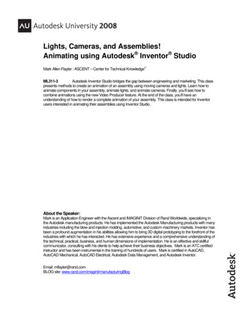
FAMU System Operation:X(Set point)The above graph illustrates the dehumidification process. The intake airtemperature is reduced below the dew point. Moisture is removed from the air reducingthe dew point and air temperature to point X. The air is then warmed by the electricheater to the set point.The FAMU control will attempt to keep the exhaust air temperature within 2 F ofset point and humidity below the humidity set point.01/14 4 OTFAMU Operator's Manual
Viewing System Status (FAMU View Mode)Line VoltageIntake HumidityCurrentFrequencyLoop WaterTemperatureLine voltage, line frequency, system current, inlet humidity, and loop watertemperature can be viewed on the display. In the off mode or any operating mode, pressand hold either center touch area to view the status. To exit the status view, press andrelease any touch area on the display.Fault Messages:RH Inlet Sensor Trouble (FAMU)A problem exists with the intake humidity and air sensor.RH Outlet Sensor Trouble (FAMU)A problem exists with the exhaust humidity and air sensor.Jumper settings:Hardware jumpers are provided on the FXII power supply to provide additionalfunctions. See Programmable Parameters for additional configuration settings.Display Selection:JP9 JP11OLEDOFF OLEDUsageOLED display.Configuration:System JP7 JP8 UsageFAMUONOFF ALL01/14 5 OTFAMU Operator's Manual
INSTALLATION INSTRUCTIONSCONTROL BOXThe control box has a NEMA 12 (IP 52) rating. Mount the box in a protected area contusive with itsrating. In mounting locations where the control box is subject to harsher environmental conditions, higherrating enclosures are available. Alternatively, the installer can provide additional protection/shielding forthe box.An air space is required behind the box for heat-sink purposes. Use the rubber stand-offs provided withthe box for mounting, or use alternate methods. Do not mount the box flush to the bulkhead.Vertical is the recommended mounting position.All wiring and cable shall have a drip loop when exiting the box.Secure all wiring and cables after they exit the box. This prevents stress on the control board connectionsand prevents damage to the board should the cables be pulled.COMPONENT WIRINGThe circuit board inside the control box has designations printed under the terminal strip.Do not wire the components using the board designations.Wire the components using the wiring diagram.If the diagram is not available, use the following designations:Power Supply L1 to AC –L1Power Supply L2 to AC-L2Fan L1 to Pump L1Fan L2 to Comp L2Water Valve L1 to Valve L1Water Valve L2 to Pump L2Electric Heater L1 to Fan L1Electric Heater L2 to Fan L201/14 6 OTFAMU Operator's Manual
OLED DISPLAYMount the display in any position but ensure that the control face can be easily accessed and viewed foroperation and programming.Make sure there is enough clearance in the cavity behind where the display is to be mounted. Rememberthat the display cable must be easily accessible and removable. Do not crush the cable in the cavity. Aminimum of 2” clearance is required.Ambient conditions around the display shall not exceed 95 % Non-condensing Relative Humidity. Norshall the operating temperature drop below 0 F or rise above 180 F.VIMAR idea 16713 bezels are used for mounting the display.The display bezel accepts Vimar or Gewiss type frames.There are two screws provided with the bezel for mounting in soft materials such as wood. Werecommend drilling pilot holes prior to fastening. These screws can be easily removed from the bezelwith finger pressure if alternate mounting methods are required.Once mounted, plug the display cable into the back of the display. Secure the cable near the display thisprevents damage to the display should the cable be pulled.RELATIVE HUMIDITY/TEMPERATURE SENSOR BOARDSProvided are two Relative Humidity/Temperature Sensors circuit boards as part of the kit. One sensorboard mounts in the Intake air stream between the coil and filter. The other sensor board is located in theoutlet air steam.Both sensor boards and their corresponding cables are identical. Do not cross the connections whenplugging into the main control board. If the inputs are crossed, the system will not function correctly.The markings on the main control board are INTAKE & EXHAUST. The Intake air is the sensor boardbetween the coil and filter; the Exhaust air sensor board is in the outlet of the blower.Secure the cables once plugged into the sensors and main board. This prevent damage to the boardsshould the cables be pulled.01/14 7 OTFAMU Operator's Manual
CIRCULATION WATER SENSORCirculation water temperature monitoring is via a glass temperature sensor. This sensor is required forcorrect operation of the water valve and electric heater.The sensor mounts on the supply water pipe feeding the air handler. The supply water feed is the bottompipe connected directly on the water valve.Affix the sensor firmly to the pipe ensuring that the entire length of the sensor is in contact with the pipe.If using a small hose clamp to secure it, do not over-tighten and crush the sensor.A metal housing encapsulates the glass sensor. Damage can still occur if too much pressure is applied.Insulate the sensor once attached.The connector end of the cable plugs into the center socket on the board, marked OUTSIDE.Secure the cable once plugged into the main board. This prevents damage to the board should the cable bepulled.01/14 8 OTFAMU Operator's Manual
Programmable Parameters:Descriptions of programmable parameters, factory default values, and allowablevalues are shown in the program parameters tables. Installed options and parameterselections control which parameters are displayed. Some parameters are not availablewith older revision displays. Separate tables are provided for DX, AH, and FAMU unitsfollowing the parameter descriptions. The DX and AH features are not used; thereforethose parameters are not included in this manual. FX II power supply jumpers must beproperly configured prior to setting parameters.Entering the program mode:To enter the program mode the display must be in the off mode. Press and holdthe On / Off symbol for 3 seconds. Press the right arrow to advance to the next parameterand press the left arrow to go back to the last parameter. Press the up or down arrows tochange the parameters value. Exit the program mode when finished by pressing the X orwait 60 seconds for the display to exit.Parameter description:o System units: (ALL)Degrees Fahrenheit ( F) or degrees Celsius ( C) can be selectedo Display brightness: (ALL)Display brightness can be set from 4 to 15 to suit room lighting. Brightness willchange as the number is changed.o Screen saver brightness: (ALL)Number values from 0 to 8 can be set to suit room brightness and the unit willoperated as described in the screen saver section. Setting the parameter to 0 willcause the display to show nothing when in screen saver.o Temperature calibration: (ALL)This parameter allows the user to calibrate the room air temperature sensor. Theroom temperature will be displayed and can be adjusted /-10 F or /-5 Co Normal water valve operation: (AH, FAMU)This feature allows service personnel to force the water valve open to facilitatebleeding air from the system. Selecting override will force the water valve openfor four hours. Touch the on/off symbol to cancel this operation01/14 9 OTFAMU Operator's Manual
o Configure System: (ALL)This option selects between Fresh Air Makeup Unit (FAMU), Direct Expansion(DX) or Air Handler (AH) operation. On later software revisions, selecting achange requires confirmation. A Y or an N appears next to the change arrows.Press the Y to confirm the change or N to cancel the change. The display willreturn to show “Configure System” with your selection. The system can only beoperated in famu configuration. Do not change to DX or AHconfiguration.Changing the system configuration will reset all parameters tofactory defaults.o Humidity set point: (FAMU)This parameter sets the percent of relative humidity threshold for the fresh airmakeup unit as measured at the air intake. If the percent of relative humidityrises to the programmed level, the control will begin dehumidifying air andcontinue until the relative humidity drops to five percent below the set value.o Reset parameters: (ALL)To reset parameters to factory defaults, select YES and then exit the programmode by pressing the X in the top left of the touch screen. The display willshow EEPROM RESET then show the room temperature in the off mode. TheFAMU parameter is not reset.Fresh Air Make Up Unit (FAMU)Programmable Parameters TableDescriptionDefaultSystem unitsDisplay brightnessScreen saver brightnessTemperature calibrationNormal valve operation F1540Normal valve operationConfigure SystemHumidity set pointReset ParametersFAMU50No01/14 10 OTFAMU Operator's ManualValue F or C4 Minimum 15 Maximum0 to 8Ambient /- 10 FNormal valve operation orValve overrideAH, DX, FAMU35 to 65No or Yes
SpecificationsGeneral:Set point rangeAmbient temperature range displayedTemperature sensor accuracyLow voltage limit 115 VAC unitsLow voltage limit 230 VAC unitsLine voltage limitFrequencyMinimum operating temperatureMaximum operating temperatureMaximum RH conditions (Board and display)Maximum length of the display cableMaximum length of the Outside air sensor cable55 F to 85 F12.7 C to 29.4 C5 F to 150 F2 F at 77 F75VAC175VAC250VAC50 or 60 Hz0 F180 F95 % Non-condensing75 Feet50 FeetApplication:Fresh Air Make Up Unit(FAMU)RH measurement rangeElectric heater output(Connected to Fan L1 and L2)Valve output MAXFan output MAX(Connected to Pump L1 and L2)5% to 100%20 Amps Maximum10 Amps Maximum10 Amps Maximum01/14 11 OTFAMU Operator's Manual
01/14 12 OTFAMU Operator's Manual
INSTALLATION OVERVIEWFAMUMAKE-UPAIRELECTRICALBOXAC WIREHARNESSEXHAUST TEMPERATURE /HUMIDITY SENSOR TO BEMOUNTED IN AIR OUTLETDINTAKETEMPERATURE /HUMIDITY SENSORTO BE MOUNTED INAIR INLET8 CONDUCTOR SHIELDEDDISPLAY CABLEMAKE-UP AIR6 CONDUCTOR SHIELDEDSENSOR CABLE-GLASSFAMU TOUCH SCREENTEMPERATURE CONTROLDETAIL D01/14 13 OTFAMU Operator's Manual
1419 W. Newport Center Drive, Deerfield Beach, FL 33442Tel: (954) 421-1717 Fax: (954) 421-1712 www.technicold.comNorthern Lights and Technicold are registered trademarks of Northern Lights, Inc. 2014 All rights reserved. Litho USA.OTFAMU
To enter the program mode the display must be in the off mode. Press and hold the On / Off symbol for 3 seconds. Press the right arrow to advance to the next parameter and press the left arrow to go back to the last parameter. Press the up or down arrows to change the parameters value. Exit the