Transcription
Lights, Cameras, and Assemblies!Animating using Autodesk Inventor StudioMark Allen Flayler : ASCENT – Center for Technical Knowledge ML311-3Autodesk Inventor Studio bridges the gap between engineering and marketing. This classpresents methods to create an animation of an assembly using moving cameras and lights. Learn how toanimate components in your assembly, animate lights, and animate cameras. Finally, you’ll see how tocombine animations using the new Video Producer feature. At the end of the class, you’ll have anunderstanding of how to render a complete animation of your assembly. This class is intended for Inventorusers interested in animating their assemblies using Inventor Studio.About the Speaker:Mark is an Application Engineer with the Ascent and IMAGINiT Division of Rand Worldwide, specializing inthe Autodesk manufacturing products. He has implemented the Autodesk Manufacturing products with manyindustries including the blow and injection molding, automotive, and custom machinery markets. Inventor hasbeen a profound augmentation in his abilities allowing him to bring 3D digital prototyping to the forefront of theindustries with which he has interacted. He has extensive experience and a comprehensive understanding ofthe technical, practical, business, and human dimensions of implementation. He is an effective and skillfulcommunicator, consulting with his clients to help achieve their business objectives. Mark is an ATC certifiedinstructor and has been instrumental in the training of hundreds of users. Mark is certified in AutoCAD,AutoCAD Mechanical, AutoCAD Electrical, Autodesk Data Management, and Autodesk Inventor.Email: mflayler@rand.comBLOG site: www.rand.com/imaginit/manufacturingBlog
Lights, Cameras, and Assemblies! Animating using Autodesk Inventor StudioIntroductionEngineering and marketing have a lot in common. Engineers need to leverage marketing in designs, andmarketing needs to leverage designs from engineers. This is the essence of collaborative engineering. Whatmost companies don’t realize is that the engineer’s data holds more power than it ever did before withAutodesk Inventor .The Studio package that comes with all versions of Inventor utilizes the engineer’s data to make high impactpresentations, marketing collateral, manual/catalog documentation, and more. If this capability is notunderstood or realized, companies can end up spending a hefty sum of money in third party contracting,additional software, and longer lead time to market. Inevitably, smaller companies get left behind becausetheir budgets cannot afford this luxury. With Studio companies can leverage all of these tasks within a singlesoftware; Autodesk Inventor.Access to StudioStudio can be accessed in any Part (.ipt) or Assembly file (.iam), as well as, Sheet Metal and Weldment files.Presentation and Drawing files have no access to Studio. To access, select Applications Inventor Studiofrom the main menu.Styling your Studio,,Surface, Scene, and Lighting Styles all combine for the overall quality of the animation. These need to be setup prior to an animation for a rich Studio output. These styles can be set up in your templates, Styles Library,or created on the fly. Here is a brief recap of these styles: Surface Styles correspond to color styles found in theStyles Library. Material properties are assigned a color inthe iProperties, and more properties for these colors areavailable in Surface Styles. Here we have the controls forvarious aspects of colors, reflections of the surface,opacity, diffusion, and bump map settings.to get and assign different styles to faces (inUsepart mode) or components (in assembly mode) to change their effects. The applied color and bump mapmay not appear correctly on the Inventor model, but the rendered image will show the correct color. Scene Styles are essentially how the background orenvironment is set up. It controls background for single andgradient colors, reflective planes, images, and sphericalimages. Consider using real life image backgrounds for yourbackdrop in your renderings.3
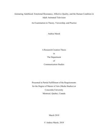
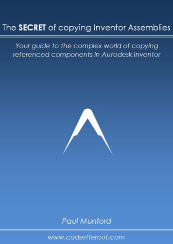
Lights, Cameras, and Assemblies! Animating using Autodesk Inventor Studio Lighting Styles contain one or more light objects that define theoverall lighting for a model. Blue Hue Lighting, as shown, is anexample of a lighting style that contains four lighting objects. Alighting object is a source of light that can be one of three types:Directional, Point, or Spot which all have their own setting tabs forGeneral, Illumination, Shadows, and a light specific tab.Unlike Scene and Surface styles, Lighting styles are not inherently active on a new Studio Animation soyou must set one active (right click on it) to work with it in the animation.To create a new light within a selected lighting style, clickTypeDescriptionDirectionalSimulates distant lightsources, such as the sun. Ithas a direction, but noposition.PointSimulates a point source. Ithas a position and it radiateslight in every direction.SpotSimulates a spot light. It has aposition and direction. A Spotlight emits light in the shapeof a cone with two degrees ofintensity. The most intensearea is located within theinner area of the cone of lightand the less intense area islocated within the outer areaof the cone of light.above the listed Lighting styles.SymbolWrapper AssembliesWhen you have a typical piece of equipment or product, it is beneficial to create a standard room/scene torender these objects. For example, if you make staplers you may want a scene with other office supplies forall your marketing or presentations. To work efficiently, create an assembly that contains all the props and setup their lighting, scene, and surface styles so that the only work that needs to be done is the work on the newproduct. The props can be used over and over again, as needed Wrapper Assemblies can be as simple as afloor and two walls, or as elaborate as an entire furnished room or industrial backdrop, as shown below.4
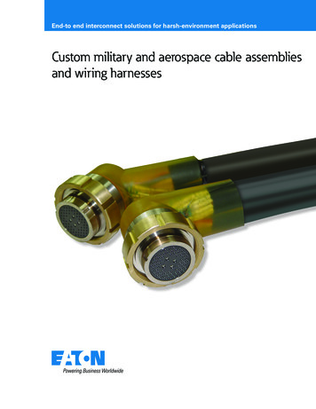
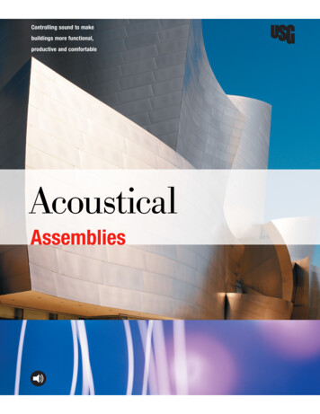
Lights, Cameras, and Assemblies! Animating using Autodesk Inventor StudioLocal LightsLocal lights differ from lighting styles in that they are discrete lights (Point and Spot only) that exist in thescene but not in a predefined lighting style. Local lights have the same controls as discrete lights. They aregreat to show LEDs, panel lights, illuminations, switches, and much more. They also have the uniqueadvantage of traveling with their components if moved in an animation. Local lights can only be alteredthrough an animation when the light is at the top level assembly.Camera CreationUse the camera command to create user cameras for different viewing control options. With the dialog boxopen, select a Target for the Camera and a preview displays for the camera direction. This positioning isnormal to the Target. For the Position, choose a point on the normal vector. Clicking on the Position orCamera graphic elements brings up 3D Move/Rotate tools to more precisely place them. Zoom is controlledby the extents of the camera shot or using the slider or input section. Roll angle is the tilt of the camera in itsposition. You must also choose either the Orthographic or Perspective (converging lines) Projection types.Depth of Field is used to control focus limits on the camera in the form of f-Stops and Focus Limits. This isonly available on Perspective projections.Zoom BoxPositionDepth of FieldMarkersDepth of Field OptionsDescriptionFocus LimitsNear – specifies the distance at which objects are clear (green plane)Far – specifies the distance at which objects are out of focus (blue plane)f-Stopf-Stop – value for depth of field; lower the number the narrower the depthFocus Plane – pick a known planar surface to set the f-stopLink Focus Plane tocamera targetWhen linked, moving the camera target also modifies the focal plane location.5
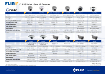
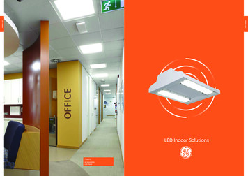
Lights, Cameras, and Assemblies! Animating using Autodesk Inventor StudioUnderstanding the Animation EnvironmentInventor Studio is designed to use intelligence from the assembly to grant movement within your animation.The biggest key factors here are constraints, position, and the assembly state before entering Studio.Consider using Design Views and Representations to control your assembly’s positioning and componentvisibilities. Many users use the Master views as the start point.Because Studio animates constraints, you work with existing constraints in the environment based on thedegrees of freedom in the components. Animation commands are directly related to components and theirconstraints. If they are constrained together then they will move together, if they are not they will moveindividually. Studio also gives you the power to control suppression of constraints to grant movement and notaffect the Assembly environment’s constraints.In general, large assemblies do not respond well to all or most of their constraints being turned off so usesuppression sparingly. Consider, grounding all or some of the components to essentially eliminate theintelligence of the constraints. In this case the components work like the Presentation files. This can meanmore or less work depending on your design intent and how well you know your assembly.Storyboards are helpful to set up a plan for the animation before beginning work in Studio. Take some time tocreate either paper or electronic storyboards.StoryBoardPro screenshot o)Consider camera movement, component movement, component opacity and fades, lighting elements,animation length, production effects such as gradient wipes and shot fades. Begin thinking about your Studioanimation during the engineering design process. Use theas a visual reference for storyboarding.command to save a JPG or a BMP6
Lights, Cameras, and Assemblies! Animating using Autodesk Inventor StudioAnimation TimelineWhen working with any animation dialog box, the Animation Timeline dialog box appears.IconDescriptionSets the current time to the beginning (0 seconds) or end of the animation,Plays the animation in forward or reverse,Toggles between repeating and not repeating the animationOpens the Render Animation dialog boxCreates a camera action that ends at the current timeOpens the Animation Options dialog box and allows you to specify the duration of the animation in minutes andseconds.Click to equate the total duration to the sumof the durations of all the specified actions.You can also change the default Velocity Profile for Animation commandsSpecify the Velocity in Percentage or Timeand their default values. Smallest incrementfor time is 1/10 of a second.Expands the actions editor. Actions are listed on the left side, while their start, duration, and end times arerepresented on the right side. Use this dialog box to view, edit, and delete existing actions. Modify an action byright-clicking on the desired action duration bar and selecting Edit, Delete, Mirror, or Copy Action. You canalso adjust the durations of actions directly by dragging the duration bars.7
Lights, Cameras, and Assemblies! Animating using Autodesk Inventor StudioWhen the Studio environment is activated, the state at which activation occurs is Frame 0 in the animationtimeline. Studio can have more than one animation. For instance Block A is Mated to Block B in animation1,but in animation2 Block A is Mated and animated away 5 units to Block B. Animation1 is not affected by thissince they are two different animations. Now if Block A and Block B are modified in the Assembly itself andnot Studio, they would both change.Common Animation Command ControlsEach animation command dialog box varies, but here are the common icons and their uses.OptionDescriptionStarts the action at the time the previous action endedSpecifies the time to begin the actionPerforms the action instantaneously (in one frame)Start time of actionDuration of actionEnd time of actionEnds the current action definition, advances the timeline by the New Action Increment value, and begins a newaction of the same type.The Acceleration tab, as shown below, is common among all animation command dialog boxes. This tabcontrols the speed of an action as it reaches its target. You can define the percentage of time or actual timefor an action to reach its speed and wind down. (Not available with theoption.)8
Lights, Cameras, and Assemblies! Animating using Autodesk Inventor StudioAnimation CommandsThere are a number of animation commands that can be used in Studio to create animations. These enableyou to animate components, constraints, fading, parameters, positional representations, cameras, and lights.To access these animation commands, use the commands in the Inventor Studio Panel or right-click on anobject in the browser bar and select its corresponding animation option. The animation commands will differdepending on the type of object you are right-clicking on. For example, a component provides the AnimateComponents and Animate Fade options, while a constraint provides Animate Constraint, and an animationfavorite provides Animate Parameters, as shown below.Animate Constraints(Select) toggled on, select one or more constraints from the browser bar to animate. EssentiallyWithAnimate Constraints is used to drive offset values for constraints from start to end values. This relies on theintelligence of your assembly and how that intelligence is applied to the mechanical movement.When a Constraint is selected a start value is automatically populated and an end value is required to drivethe animation. Use the Suppress and Enable options as instantaneous actions to turn on and off constraintsthroughout the animation.OptionDescriptionAnimates a change in alinear or angular constraintvalue. Enter a value. Theinitial value for theconstraint is shown bydefault.Suppresses a constraintthat may preventmovement for an action.Enables a constraint9
Lights, Cameras, and Assemblies! Animating using Autodesk Inventor StudioAnimate Components
Autodesk Inventor . The Studio package that comes with all versions of Inventor utilizes the engineer’s data to make high impact presentations, marketing collateral, manual/catalog documentation, and more. If this capability is not understood or realized, companies can end up spending a hefty sum of money in third party contracting,