Transcription
1CSWP Segment #1 Concept ReviewSegment 1: (90 Minutes) Creating a part from a drawing Using linked dimensions and equations to aid in modeling Using equations to relate dimensions Updating parameters and dimension sizes Mass property analysis Modifying geometry on initial part to create a more complex part Modifying parameters on the part at different stages while maintaining all other dimensions anddesign intentStart the exam by making sure you are in the correct unit system and selecting your material.Schedule:Monday: Review concepts and (Pages 2-9).Tuesday: Go through the practice exam (Pages 10-16)Wednesday: Self-study subjects that are trouble areasThursday: Take the timed practice exam (Page 17)Friday: Take the CSWP Segment #1
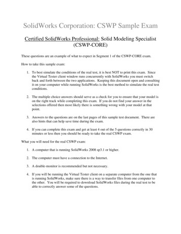
2Creating Global VariablesStart a new part in SolidWorks. Go to tools Equations. The box shown below will pop up. Createglobal variables “A” and “B” as shown. Don’t forget the quotation marks.Create a rectangle sketch. Set the length using variable “A” and the width using variable “B”.This is done by clicking the smart dimension tool, selecting the entity you wish to dimension (in this casethe length or width) and then typing ”A” or ”B” in the dimension box.
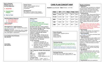
3You can also create global variables as you go. Draw a circle anywhere inside your rectangle. Dimensionthe diameter by typing ”C” in the dimension box. Click yes to create new global variable. It will thenprompt you to enter the value for C; type 25. A new global variable “C” is created.Now go to the design tree. When you expand the equations folder, you should be able to see all yourglobal variables. Right click the equations folder and select “manage equations”. Click in the box below“C” and create a new global variable “D”. Set “D” equal to “A”/2. Now go back to your sketch andextrude it to a length of “D” by typing ”D” for the distance to be extruded.Working with the Rollback Bar.Start by sketching two 27mmx100mm rectangles spaced 25mm from the origin. Extrude them MidPlane 27mm. This will create two pillars.
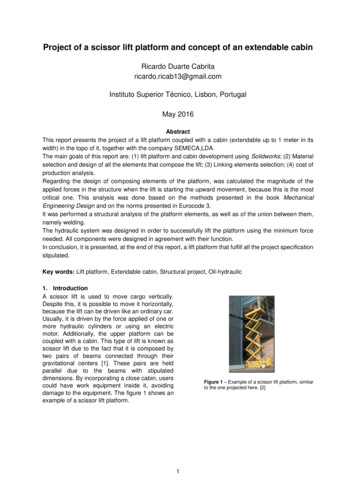
4Next, sketch and extrude a 23x25 rectangle on the right plane. Extrude it 100mm Mid Plane. This willcreate an ‘H’ shape.Now, start a sketch on the top surface of the ‘H’. Use the convert entities and offset entities features tocreate the sketch shown below. Offset the inner square 2mm. Next, do an extrude cut 50mm that isoffset 25mm.
5As you can see, doing this causes a gap between the pillars. One way to fix this would be to create theconnection after making the final cut. In this example, that would be an easy solution. However in morecomplex parts, it is not always that easy.Next, delete the last cut you made (Feature and sketch). Use the roll back bar to move up the designtree as shown.
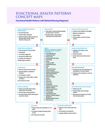
6Now with the roll back bar as shown, sketch the cut you made before. Here is the drawing in case youforgot. Again, use the convert entities and offset entities features. Go ahead and make the cut again.As you can see, we were able to place a feature higher up in the design tree by using the roll back bar.
7Christian’s notes with commentaryTest One:This was the first part that they have you build (from drawings). Quite a few of the dimensions on thedrawings are given as letters and the values are given later in the problem. The lettered dimensions arethe ones that will be changing in the subsequent problems so make sure that you use design tables,global variables or some other way to keep track of all of the changing numbers.Something that needs to be taken into account in this problem is where you place your origin. Take anextra minute to look through the drawings and select a good origin. This will reduce the number ofdimensions and construction lines that are needed and save a lot of time.The second question just had you change all of the lettered dimensions so if you have them set up right(global variables!) this problem will only take 30 seconds.The third question has you add some cutouts and extrusions noted in the drawings as well as change thelettered dimensions.
8The fourth question has you change the lettered dimensions again.The fifth and six questions follow the same pattern with adding more details and then changing thelettered dimensions.These questions are the trickiest on the part. I recommend knowing how to work with the rollback barto create features earlier on the design tree. Doing this will make this problem significantly easier.You do need to be fairly quick with your modeling. I rushed through the test and I barely hadenoughHere are all of the websites that I looked through as prep for the exam. I found them to be very helpful. gn-point.com/media/152467/Tips And Tricks To Prep For The A ExamPractice Questions.pdf
9Review for the CSWP Exam Part 1 (Chris Fraser and Jacquelin Remaley)This portion of the exam is almost exactly like the part creation section of the CSWA. In essence, you aregiven a basic part and asked to modify its features and existing dimensions, taking masses along theway.The key thing to remember here is that your gut instinct on how to create the part may work when youhave unlimited time, but here you only have 90 minutes. You need to seriously think about the order ofthe features you create and how they relate to ease of construction later. Take a look at all the futureedits to the part you will do, consider how those would be easiest to edit, and create the initial partaccordingly.General tips:----Include all global variables from the beginning. Create one, then go into ‘Manage Equations,’and create them all, so referencing them is easier.When referencing a variable, use correct syntax. ”A” is different from “A”. Using the equal signtells Solidworks to reference that variable name forever, while no equals sign tells it to grab thatdimension once, and never again. Changing the dimensions after this won’t change the value ifno equals sign is used.Take advantage of extruded cuts to remove material all at once.The rollback bar is your friend! You can rollback to before an extruded cut is made, createanother feature, and move the bar back down, unsuppressing everything. The cut will also affectthe feature you just created.Leave fillets and chamfers till the end, unless they can be used in a mirror feature or other cut.When adding fillets, use the features fillet, not the sketch fillets, you will get an incorrect mass ifyou use the sketch fillet.Offset entities is handy when you need the offset of an entire face.Save the part you use on every question as a separate part, even if you only changed the valuesof the variables.The following pages contain drawing images and questions similar to the ones on the exam. If you cancomplete these, you should do just fine with plenty of time to spare.
10Question 1Create the part in Solidworks, using the following values for the given variables. Use the unit system MMGS, andAlloy Steel (density 7700 kg/m 3). The cutouts on the webs are on both sides (there should be 4 total).A 100B 70C 10D 80E 60Z (C E)/3What is the mass of the part in grams?a)b)c)d)6702.5926207.4553501.7651609.93
11Question 2Modify the part to have the dimensions given.A 110B 73C 11D 88E 60Z (C E)/3What is the new mass of the part?a)b)c)d)51609.9360966.5357760.0855024.29
12Question 3Use the following drawing to make modifications to the existing part. Some dimensions are the same, and somehave been changed. Use the values listed (in mm) for the variables in the drawing. All holes are thru unless listedotherwise. The center point of the Hole Wizard is coincident with the 90 degree corner of the triangular web.Material: Alloy SteelA 120B 60C 15D 79E 72F ANSI Metric Countersunk HeadM20, Normal fitEnd condition: thru allY A DZ (C E)/3What is the mass of the part in grams?a)b)c)d)56984.127633.3058776.437856.37
13Question 4Use the following drawing to make modifications to the existing part. Some dimensions are the same, and somehave been changed. Use the values listed (in mm) for the variables in the drawing. All holes are thru unless listedotherwise. Note the equation for Y has changed.Material: Alloy SteelA 120B 60C 15D 79E 72F ANSI Metric Countersunk HeadM20, Normal fitEnd condition: thru allY (D-40)/2Z (C E)/3What is the mass of the part?a)b)c)d)57152.6259162.657683.4657876.73
14Question 5Modify the part to have the dimensions given.A 125B 63C 18D 75E 72Y (D-40)/2Z (C E)/3What is the new mass of the part?a) 60438.79b) 60966.53c) 7849.19d) 58024.29
15Answers:1)2)3)4)5)DBCBAThe Part Files can be found:Shared engineering Senior Design Course Folders ME 490 CSWP Part 1
16Timed Review Exam:This website will walk you through the exam process and show you how to take the practice Exam.pdfGo to https://solidworks.virtualtester.com/#home buttonDownload the TesterPro ClientOpen the Application and create an account or log in if you already have an account.A list of tests should appear. Scroll to the bottom and find the CSWP segment 1 practice exam. Youwill be able to take this practice exam once for free.
Review for the CSWP Exam Part 1 (Chris Fraser and Jacquelin Remaley) This portion of the exam is almost exactly like the part creation section of the CSWA. In essence, you are given a basic part and asked to modify its features and existing dimensions, taking masses along the way. The key thing to remember here is that your gut instinct on how to create the part may work when you have .