Transcription
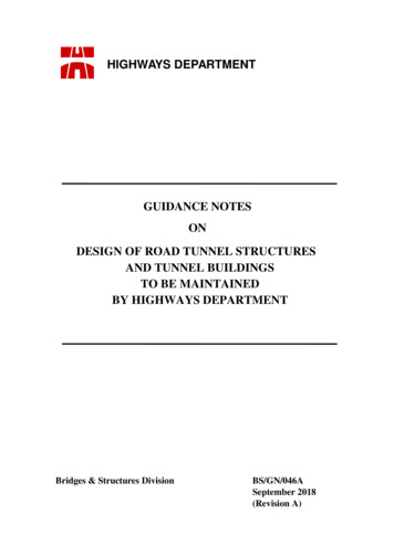
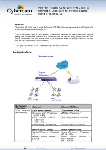
Building Tomorrow’s SocietyBâtir la Société de DemainFredericton, CanadaJune 13 – June 16, 2018/ Juin 13 – Juin 16, 2018TUNNEL SEGMENT GASKET DESIGN – SOLUTIONS AND INNOVATIONSBakhshi, Mehdi1,2 and Nasri, Verya112AECOM, USAmehdi.bakhshi@aecom.comAbstract: Watertightness of tunnels must be ensured during design and construction to prevent waterinfiltration and minimize maintenance and repair costs, maintain operational safety, and protect insideequipment. In one-pass segmental lining system, watertightness is guaranteed by segments and gasketsplaced between segments joints. In this paper, a procedure is provided to select gasket materials, solutionsfor different working water pressures, appropriate safety factor considering relaxation, and gasket profilesconsidering size of tunnel, tolerances and required construction gap/offset. Watertightness tests, gasketload-deflection tests, and details of gasket groove design are discussed. Gasket short-term behavior wasprovided in terms of a load-deflection curve, and discussion is made on design of connection systems formaximum gasket load in this curve or in a less conservative approach after short-term relaxation. Gasketgroove design is briefly explained with a focus on simulation of impact force in a gasket groove as ahydrostatic distribution. New developments in gasket systems are introduced including anchored gasketsand most recently developed fiber anchorage technology for gaskets; soft corner solutions to eliminate pointloading using pin-based cavities; and new repair method for post sealing of segment joint based on directdrilling and injection through joint sealing gasket.1INTRODUCTIONWatertightness of tunnels must be ensured during design and construction in order to prevent waterinfiltration, minimize maintenance and repair costs, maintain operational safety, and protect mechanicaland electrical equipment inside tunnels. One-pass segmental lining system nowadays is the mostcommonly-used system in TBM bored tunnels. In these tunnels, the watertightness is guaranteed by theindividual components of the support system, namely precast concrete segments and gaskets placedbetween segments and ring joints. As shown in Figure 1, gaskets are positioned around individual segmentslike a frame and primarily near the lining extrados to provide the joint tightness.The technical solutions that engineers need to implement to design segment gasket and achieve thewatertightness requirements may vary depending on project specific circumstances. The important factorsfor design and application of tunnel sealing gaskets are the water pressure, safety factor, size of tunnel andconsequently size of segments, gap and offset between segments, and tolerances. All these factors arediscussed in this paper. Load-deflection response of gasket profiles tested according to national guidelinesis explained. Gasket groove design is presented by a simplified simulation of impact force in gasket grooveas a hydrostatic pressure distribution. Latest developments in gasket systems are introduced.GC5-1
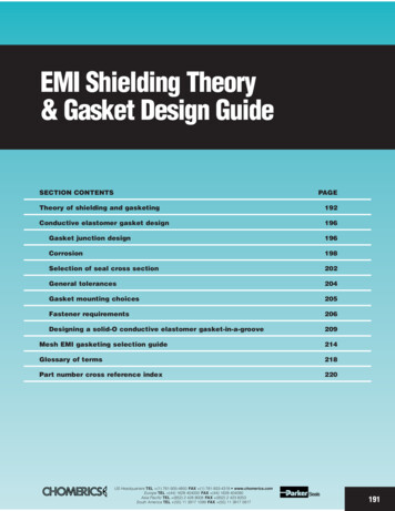
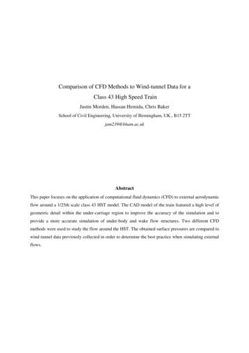
Figure 1: Gaskets positioned near the lining extrados to ensure watertightness at joints2GASKET MATERIALSRecommended materials for segment gaskets are Ethylene Propylene Diene Monomer (EPDM) rubbercompounds which have replaced the formerly used Chloroprene gaskets. EPDM compounds guarantee alife span of more than 100 years, and economically and technically most suitable material to withstandclimate and groundwater with varying water composition. EPDM rubber compound is stable enough not toreact with the environment or deteriorate in contact with other materials, such as concrete, grease, injectionmaterials and ground and groundwater anions, cations, heavy metals, volatile and semi-volatile organiccompounds. EPDM elastomer resistance to some of the substances that may found in some specificgrounds such as hydrocarbons, oils and tar are limited. However, in such cases, often due to lowconcentrations of these substances and also the embedment of gaskets in the segments joints, EPDMelastomer gasket contact with such substances does not raise any significant concern. An alternativeelastomer material which offers a better resistance to hydrocarbons, oils and tar is a ChloropreneRubber/Styrene Butadiene Rubber (CR/SBR) compound. However, CR/SBR compound offers much loweror no resistance to most of other substances such as acids, has serious application issues in ground waterwith a PH value of 2, much weaker resistance to aging and weathering effects, and weaker behavior withregard to stress relaxation over service life a tunnel. Gasket relaxation has a significant effect on long-termwaterproofing performance, and resistance against water and gas permeability. Therefore, EPDMelastomer is recommended as the most suitable material for segment gaskets. In order to provide thedesired characteristics, several material-specific requirements must be met for the gasket to perform asintended. One of these properties is hardness of the rubber compound. The BSI PAS 8810 requires amaximum shore hardness of 75 according to ASTM D2240 (2015), whereas the German STUVA (2005)and French AFTES (2005) recommendations call for a maximum hardness of 85. Other important propertiesinclude tensile strength and elongation according to ASTM D412 (2016) which are recommended to behigher than 1700 psi and 300%, respectively.3WATER PRESSURE AND GASKET DESIGNThe most important parameter for design of gaskets is the maximum water pressure. Depending on theexpected water pressure in the tunnel, different solutions and different gasket profiles are selected. Thefirst gasket generation could only withstand a maximum water pressure of 3 bar. Today, with the advanceof technology and limited offset between adjacent segments due to more accurate segment erection insideTBM, water tightness of up to 10 bar is often achievable with a standard mono-extrusion EPDM gasketprofile. As shown in Figure 2, water tightness between segments will be created through the compressionof gaskets developed during the assembly process of the segments.For higher requirements and higher water pressure, two main solutions are available. First solution includesa composite seal combining two different sealing technologies of EPDM compression gasket and ahydrophilic seal. As shown in Figure 3, this solution can be provided by the application of co-extrudedGC5-2
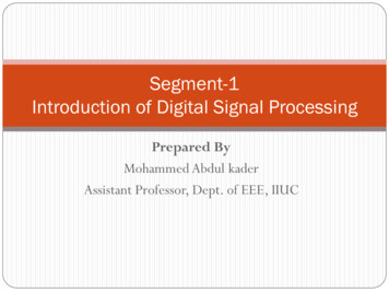
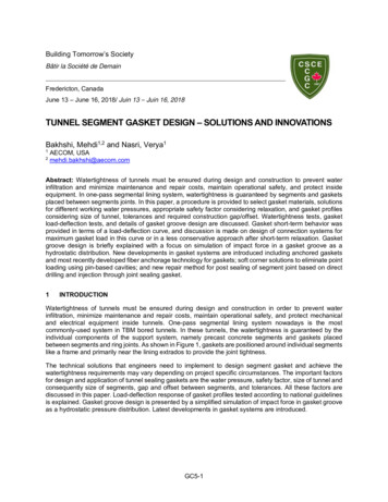
gaskets with hydrophilic layer, composite profiles with hydrophilic cord, or designing a composite solutionwith separate hydrophilic seal next to the standard EPDM gasket. Figure 4 shows effect of the hydrophilicinsertion on improving sealing performance of a composite EPDM gasket in terms of resisting higher waterpressure after several days of immersion in water. The hydrophilic cord swells under water pressure andcan act as an extra backup of the EPDM profile. Note that tests with co-extruded gaskets or hydrophilicswelling cord gaskets do not influence the test results in a short term, as the hydro-swelling takes longerthan 24 hours to react. About 50% of the swelling occur within 7 days, nearly 100% of swelling occurs within30 days. To measure the positive influence of hydro-swelling layers, long-term watertightness tests haveto be carried out. Second solution includes two sealing gaskets, one near the extrados and one near theintrados of the segment, providing double the security for the waterproofing performance. When used incombination with sealing profile connecting bars between the extrados and intrados gaskets, isolationchambers can be created that help confine any localizing leakages thus permitting precise repairs by groutinjection methods. A look at reference projects with double gaskets shows that in half of these projects noconnecting gasket bar was used. In projects with connecting gasket bar, except for one project that crossconnecting bars were vulcanized at the gasket manufacturing plant, the connecting gasket bars were gluedin place at the segment precast plant. Care needs to be taken to the fact that the watertightness of doublegasket system is defined by the higher capacity of the two gaskets, not by the sum of both gaskets’ capacity(BSI PAS 8810, 2016).Figure 2: Water tightness between segments created through gasket compressionStandardEPDMProfileCompositeProfile Composite Profilewith SeparateHydrophilic SealDouble GasketProfileFigure 3: Water tightness between segments created through gasket compressionGC5-3
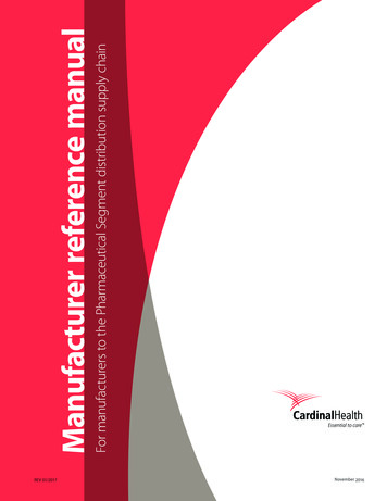
Figure 4: Effect of hydrophilic swelling cord on improving sealing performance of a composite EPDMgasket in terms of resisting higher water pressure after several days of immersion in water4GASKET RELAXATION AND FACTOR OF SAFETYIn addition to the expected water pressure in the tunnel, specifications have to define the watertightnessperformance of a sealing gasket and thereby include a safety factor that takes rubber relaxation effects intoaccount. To get a long-term post construction performance, it is crucial that the gasket profile and rubbercompound uphold the designed reaction force to withstand the applied water pressure even years after itsapplication. The majority of the relaxation occurs in the first months after installation. The relaxation can betested with so-called accelerated aging tests using an accelerated procedure with elevated temperaturesto get results within a reasonable timeframe (Figure 5). Most of specifications ask for a minimum residualcompressive stress of 60% after 100 years. This means a safety factor of 1.67 (1/0.60 1.67) is the minimumfactor of safety for gasket profiles. Considering the relaxation effects of rubber and design life of most oftunnels from 100 to 120 years, a safety factor of two is advisable to ensure that the gasket is able towithstand the design pressure in the long term. As the geometry of the gasket profile has a significantimpact on the relaxation behavior of a sealing gasket, such aging tests have to be carried out independentlyfor every gasket profile.Figure 5: Typical long term relaxation test results according to ISO 11346 (2014)GC5-4
5GASKET DESIGN BASED ON SIZE OF TUNNEL AND TOLERANCESThe width of gasket profile depends on the size of tunnel as segment thickness is a function of tunneldiameter itself. Following gasket profile widths are commonly used with regard to the tunnel diameter ascurrent industry practice. Tunnel Diameter 4m,4m Tunnel Diameter 7m,7m Tunnel Diameter 11m,12m Tunnel Diameter,Gasket Width 20mmGasket Width 26mmGasket Width 33 or 36mmGasket Width 36 or 44mmNote that in specific cases, a more conservative requirement (i.e. a wider segment profile) may berequested by the owner. Gasket size is also related to erection tolerances which in turn depend on tunneldiameter, segment size, and the connection system. Bolt and dowels as the two typical connection systemsallow for different gap and offset tolerances during the segment erection process. Gap openings and offsetsare illustrated in Figure 6. The connection system with bolts usually allows offsets up to 15mm, which canbe reduced to 5mm when precisely applied. Dowels, however, are the connection system with reducedtolerances. Note that reducing the tolerances has a major impact on the design of gasket system. With thesmaller offset range that gasket needs to cover, a gasket profile with smaller width can be selected. Also,due to reduction of gasket offset, gasket resistance pressure is often increased. In addition to smaller andless costly gasket profile, other advantages of sealing system with reduced tolerances include: Reduction of TBM erector forces ( 50%)Reduction of induced forces in connectors ( 50%) and in turn reduction in size of connectorsReduction of designed space for gasket and connection systemsMost of tunnel project specifications allow for 5 mm gap and 10 mm offset for segment gaskets. Dowelscan easily provide this requirement. However, bolts are the predominant connection system in longitudinaljoints, and contractors tend to change the conditions to higher gap and especially higher offset values toavoid an additional time and labor needed for very precise application of connections to such lowtolerances. A review of 50 international projects show that while the gap opening between segment gasketsranges from 2-7 mm, in 30% of these projects the contactors selected to use a gap of more than 5 mm.Also with offsets between gaskets ranging from 5-20 mm, contractors have chosen an offset of more than10 mm in 46% of these projects. While engineers design the gaskets for specified gap and offset in theproject specifications, they are also encouraged to consider possible larger gaps and offsets with potentialcost saving during construction due to faster erection and construction time comparing to gasket andconnection materials itself.Figure 6: Illustration of gap opening and offset before and after compressionWatertightness tests using gaskets can be performed on steel or concrete specimens. However, workingwith concrete specimens is time consuming and prone to failure. Practically only tests on steel specimensare currently carried out. Following STUVA (2005) recommendations, as shown in Figure 7, the tests areperformed on a T-joint setup in the laboratory, simulating a simplified situation at a circumferential joint withGC5-5
straight pieces of gasket profile pressing against each other at the end of a longitudinal joint. Gaskets mustensure the watertightness under all possible gaps and offsets. Therefore, it is necessary to run thewatertightness tests with different gaps and offsets. For every offset value (0 – 20 mm), the test has to runthrough a range of different gaps. For every gap, the water pressure is built up in steps of 1 bar and is holdthere for 5 minutes until the profile shows leakage. The recording of all leakage pressures under differentgaps and offsets leads to the wate
Load-deflection response of gasket profiles tested according to national guidelines is explained. Gasket groove design is presented by a simplified simulation of impact force in gasket groove as a hydrostatic pressure distribution. Latest developments in gasket systems are introduced. GC5-2 Figure 1: Gaskets positioned near the lining extrados to ensure watertightness at joints 2 GASKET .