Transcription
THE UNIVERSITY OF CALGARYSketch-Based Modeling of Parametric Surfaces using Few StrokesbyJoseph Jacob CherlinA THESISSUBMITTED TO THE FACULTY OF GRADUATE STUDIESIN PARTIAL FULFILLMENT OF THE REQUIREMENTS FOR THEDEGREE OF Master of ScienceDEPARTMENT OF Department of Computer ScienceCALGARY, ALBERTAMarch, 2006c Joseph Jacob Cherlin 2006
THE UNIVERSITY OF CALGARYFACULTY OF GRADUATE STUDIESThe undersigned certify that they have read, and recommend to the Faculty ofGraduate Studies for acceptance, a thesis entitled “Sketch-based Modeling of Freeform 3D Objects” submitted by Joseph Jacob Cherlin in partial fulfillment of therequirements for the degree of Master of Science.Supervisor,Dr. Mario Costa SousaDepartment of Computer ScienceCo-Supervisor,Dr. Faramarz SamavatiDepartment of Computer ScienceDr. Przemyslaw PrusinkiewiczDepartment of Computer ScienceDr. Oleg VeryovkaElectronic Arts, CanadaDateii
AbstractSketch-based modeling takes 2D sketch input and creates a 3D model. We presenta novel sketch-based system for the interactive modeling of a variety of free-form3D objects using just a few strokes. Our technique is inspired by the traditionalillustration strategy for depicting 3D forms where the basic geometric forms of thesubjects are identified, sketched and progressively refined using few key strokes. Weintroduce two parametric surfaces, rotational and cross sectional blending, that areinspired by this illustration technique. We extend our sketch modeling techniquesto apply to the design of B-Spline patches. We also describe orthogonal deformation and cross sectional oversketching as editing tools to complement our modelingtechniques. Rendering methods appropriate for sketch-based modeling are also presented, including rendering methods that render in the style of a drawing. Exampleswith models ranging from cartoon style to botanical illustration demonstrate thecapabilities of our system.iii
AcknowledgmentsThanks goes out to my supervisor Dr. Mario Costa Sousa and my co-supervisor Dr.Faramarz Samavati, without whom this thesis would not be. Thanks goes out to mygirlfriend Kelly Kinney Fine, without whom my sanity would not be. Thanks goesout to my parents Michael and Rose Ann Cherlin, without whom I would not be.Thanks also goes to Bob Dylan, Woody Guthrie, Leadbelly, Blind Willie McTell,Jack Hamm, Andrew Loomis, Tom Cowette, Dr. Marcia Soderman-Olsen, andShigeru Miyamoto. Thanks to Dr. Przemyslaw Prusinkiewicz for his inspirationallectures. Thanks to Dr. Victoria Interrante for teaching me computer graphics.Thanks to Dr. Sheelagh Carpendale and Leila Sujir for being excellent andunderstanding employers. Thanks to Joaquim Jorge for the many and sometimesheated discussions on sketch based modeling. Thanks to the artists Rio Aucena andSiriol Sherlock for providing their drawings and paintings used in our experiments.Of course, thanks goes out to my defense committee for taking the time to read this.Thanks finally to all the friends I have made in the Graphics Jungle! This includes(alphabetically), but isn’t limited to: John Brosz, Erwin de Groot, Pauline Jepp,Kaye Mason, Luke Olsen, Adam Runions, and Colin Smith. You guys are awesome!Thank you for playing!iv
Table of ContentsApproval PageiiAbstractiiiAcknowledgmentsivTable of Contentsv1 Introduction1.1 Contributions . . . . . . . . . . . . . . . . . . . . . . . . . . . . . . .1.2 Organization of the Thesis . . . . . . . . . . . . . . . . . . . . . . . .1672 Sketch Based Modeling2.1 Gestural Modeling . . . . . . . . . . . . . . . . . . . . . . . . . . . .2.2 Theoretical Limits of Sketch Based Modeling . . . . . . . . . . . . . .89153 Parametric Surfaces3.1 Definition of a Parametric Surface . . . . .3.2 Benefits of Parametric Surfaces . . . . . .3.2.1 Texture Coordinates . . . . . . . .3.2.2 Varying Level of Detail . . . . . . .3.2.3 Stripped Geometry . . . . . . . . .3.2.4 Reduced Storage and Transmission3.2.5 Regular Polygon Mesh . . . . . . .3.3 Common Surfaces . . . . . . . . . . . . . .3.3.1 Surface of Revolution . . . . . . . .3.3.2 Ruled Surface . . . . . . . . . . . .3.3.3 Generalized Cylinder . . . . . . . .3.3.4 Coon’s Patch . . . . . . . . . . . .3.4 B-Spline Patches . . . . . . . . . . . . . .1919202021242425252627272929.4 Stroke Capture345 Creation Phase5.1 Overview of Sketch Based Interaction5.2 Tube Surfaces . . . . . . . . . . . . .5.3 Rotational Blending Surface . . . . .5.3.1 General Description . . . . . .3940414444v.
5.45.55.3.2 Mathematical Details . . . . . . . . . . .Cross Sectional Blending Surfaces . . . . . . . .5.4.1 Cross Sections . . . . . . . . . . . . . . .5.4.2 Mathematical Details . . . . . . . . . . .B-Spline Surfaces . . . . . . . . . . . . . . . . .5.5.1 Sketch Based Design of B-Spline Patches5.5.2 Evaluating the B-Spline Patch . . . . . .474952555758596 Editing Phase636.1 Orthogonal Deformation Stroke . . . . . . . . . . . . . . . . . . . . . 636.2 Cross Sectional Oversketch . . . . . . . . . . . . . . . . . . . . . . . . 657 Rendering Phase7.1 Toon Shading . . . . . . . . . .7.2 HBED: Rendering as Lines . . .7.2.1 HBED: The First Pass .7.2.2 HBED: The Second Pass7.2.3 Efficiency of HBED . . .7.2.4 Stylization of HBED . .707075798181828 Results and Discussion849 Conclusions92A InterfaceA.1 General OperationA.2 Interface ElementsA.2.1 Menu Bar .A.2.2 Tapes . . .A.2.3 Hot Keys .A.3 Selection Mode . .A.4 Subdivision Editor.B PseudocodeB.1 Creation Phase . . . . . . . . . . . . . .B.1.1 Rotational Blending Surface . . .B.1.2 Cross Sectional Blending SurfaceB.2 Editing Phase . . . . . . . . . . . . . . .B.2.1 Orthogonal Deformation Stroke .B.2.2 Cross Sectional Oversketch . . . .vi.96969696100104105106.111111111112113113114
C GPU OverviewC.1 Reasons for using the GPU . . . . . .C.2 What is the GPU? . . . . . . . . . .C.3 The Graphics Pipeline . . . . . . . .C.4 The Programmable Graphics PipelineC.4.1 Shader Programming . . . . .C.4.2 What can you program? . . .C.5 Code Examples . . . . . . . . . . . .C.5.1 Vertex Shader . . . . . . . . .C.5.2 Phong Shader . . . . . . . . .C.5.3 Toon Shader . . . . . . . . . vii
List of Tablesviii
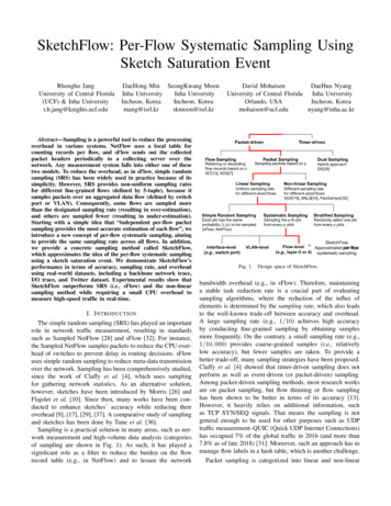
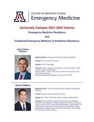
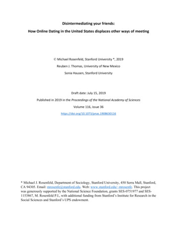
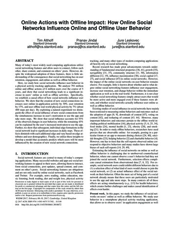
List of Figures1.11.21.32.12.22.3Traditional hand-drawn techniques for progressive shape depiction[Gol99] [DGK99] [Gup77]. Skirt drawing, Copyright 1998-2004 RioAucena. Used with permission. . . . . . . . . . . . . . . . . . . . . .A figure from an art book, “Figure Drawing For All It’s Worth” byAndrew Loomis [Loo43]. This figure illustrates various shapes byusing cross sections. Though these cross sections wouldn’t be presentin a finished work, they are useful when describing form to otherartists, or in our case, to a computer. . . . . . . . . . . . . . . . . . .A figure from an art book, “Drawing the Head and Figure” by JackHamm [Ham63]. This figure illustrates the form of the nose by usingcross sections. Though these cross sections wouldn’t be present in afinished work, they are useful when describing form to other artists,or in our case, to a computer. . . . . . . . . . . . . . . . . . . . . . .Examples from Igarashi’s Chameleon system, which allows the userto sketch shapes, perform CSG operations on them, and then paintcolor onto them. . . . . . . . . . . . . . . . . . . . . . . . . . . . . . .Examples from Owada et al’s system. Sketch based operations areused to define volume data and perform CSG operations on them. . .Examples from Araujo et al’s BlobMaker system. Also pictured isits minimalized interface. The Blobmaker system allows the user tosketch and edit variational implicit surfaces interactively. . . . . . . .Top Left: A 2D texture. The rest of the figure shows a torus fromvarious angles. It has been texture mapped according to Equation 3.1.3.2 A: A torus with only four samples in the u and v directions. B: Atorus with eight samples in the u and v directions. C: A torus with16 samples in the u and v directions. D: A torus with a high numberof samples, 210 in both the u and v directions. . . . . . . . . . . . . .3.3 A strip of four triangles. Notice that there only six vertices in all ifthe triangles can share vertices, but there are twelve vertices if thetriangles can’t share the vertices. In a triangle strip, the first triangleneeds to specify three vertices, and all other triangles need just onevertex each. Quad strips are similar to triangle strips. . . . . . . . . .3.4 Surfaces of revolution and their generating curves. . . . . . . . . . . .3451111133.1ix22232426
3.53.63.73.84.14.2Various ruled surfaces and their generating curves. (A): Two circlescan define a cylinder, shown in (B) and (C). (D): Two circles, one ofradius zero, can define a cone, shown in (E) and (F). (G) and (H):Here we see another ruled surface, the hyperbolic paraboloid. Thegenerating curves, which are just two straight lines, are shown in redand blue. . . . . . . . . . . . . . . . . . . . . . . . . . . . . . . . . . .(A-D): Here we see the four edge curves of the Coon’s patch. (E): ACoon’s patch created by using the curves pictured in (A-D). . . . . .(Left: A control mesh (red) and the resulting B-Spline patch (blue).Right: A shaded version of the same patch. . . . . . . . . . . . . . . .A seashell and the control mesh used to create it. The seashell is asingle B-Spline patch . . . . . . . . . . . . . . . . . . . . . . . . . . .Stroke capture: unfiltered stroke (left), after applying the reverseChaikin filter (middle) and the final stroke showing its control points(right). . . . . . . . . . . . . . . . . . . . . . . . . . . . . . . . . . .An unfiltered stroke is shown in (a). (b-f) show successive applicationsof the reverse Chaikin subdivision. Each time the subdivision is applied, the curve is smoother but deviates from the original, unfilteredstroke. . . . . . . . . . . . . . . . . . . . . . . . . . . . . . . . . . . .(a): A tube surface created with one stroke. (b): a rotational blending surface created with two strokes. (c): A cross sectional blendingsurface created with three strokes. (d): a B-Spline patch created withfour strokes. . . . . . . . . . . . . . . . . . . . . . . . . . . . . . . . .5.2 Here are some models created with our sketch system, and parts ofeach model were created using tube surfaces. The flower uses a tubesurface for the stem, and the demon’s arms and pitchfork were alsocreated using tube surfaces. Shown below the models are the strokesused to create them. . . . . . . . . . . . . . . . . . . . . . . . . . . .5.3 Construction of a tube surface. Left: S(u) is the input stroke. Acircular cross section, Cu (v) is pictured in red. It lies in a plane whosenormal is tangent to S(u) at u, and is centered at S(u). This tangentvector is shown in purple. For each u, we use give the associated circlea constant radius. The resulting tube surface is shown on the right. .5.4 A rotational blending surface. The left and middle images show theconstructive curves (green), ql (u) and qr (u), the center curve c(u)(blue), and a circular slice of the surface, denoted tu (v). The rightimage shows a completed surface overlaid with the blending curvesformed by holding v constant. . . . . . . . . . . . . . . . . . . . . . .2830303136375.1x41424345
5.5A variety of shapes is possible to generate using few strokes (top row)by using just rotational blending surfaces. We created the pear in fourstrokes, the candle in eight and the laser gun in six strokes. . . . . . .5.6 A unit circle from the cylinder has been mapped via an affine transformation to the pear. All rotational blending circles can be thoughtof as a cylinder where each circle in the cylinder has undergone atransformation. . . . . . . . . . . . . . . . . . . . . . . . . . . . . . .5.7 From left to right: sketching two constructive strokes (black), onecross sectional stroke (red) and the resulting leaf model in front andside views. . . . . . . . . . . . . . . . . . . . . . . . . . . . . . . . . .5.8 Modeling a sword blade using cross sectional blending surfaces. Toprow, left to right: drawing the constructive curves only (dotted lines)results in a perfectly rounded object. Sketching the cross sectionaloutline (red line) results in a better, sharper, faceted blade. Bottomrow: the sword in a different view. Notice the final surfaces, withsharper features . . . . . . . . . . . . . . . . . . . . . . . . . . . . . .5.9 A sphere being projected onto a 2D plane. The dotted line shows howthe 3D shape is being projected onto a 2D plane. Notice that thedotted line passes through two points on the sphere, one on the backof the sphere, and one in front. This means that two points on thesphere are projected to the same point on the 2D plane. . . . . . . . .5.10 The user hovers the mouse cursor near where he wishes to create across section. A sample cross section, indicated by the dashed andsolid grey lines appears. This sample cross section is the similar tothe cross section of a cylinder, and is inspired by the style of Figure5.12. The dashed grey line indicates a concave
1.3 A figure from an art book, “Drawing the Head and Figure” by Jack Hamm [Ham63]. This figure illustrates the form of the nose by using cross sections. Though these cross sections wouldn’t be present in a finished work, they are useful when describing form to other artists,