Transcription
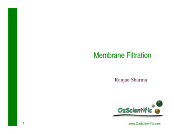
Membrane FiltrationRanjan Sharma1www.OzScientific.com
Traditional vs membrane filtrationTraditional2Membrane
Membrane filtrationAPV3
Batch membrane filtration plantFeed productConcentration loopPermeateCooling medium1. Product tank2. Feed pump3. Circulation pump4. Strainer5. Membrane module6. CoolerDairy Processing Handbook. Published by Tetra Pak Processing Systems AB, S221 86 Lund, Sweden.4
Membrane filtration spectrumDairy Processing Handbook. Published by Tetra Pak Processing Systems AB, S221 86 Lund, Sweden.5
Filtration spectrumGEA6
Membrane filtration - dairyDairy Processing Handbook7
Filtration processes - dsWaterBacteriaionsMFUFNFRO8
Membrane filtration applications Reverse osmosis (RO) Concentration of solution by removal of water Concentration of organic components by removal of part ofmonovalent ions like sodium and chlorine (partialdemineralisation) Nanofiltration (NF) Ultrafiltration (UF) Concentration of large and macro molecules Removal of bacteria, separation of macromolecules Microfiltration (MF)9
Comparison of membrane processesWagner, 2001, Membrane Filtration Handbook10
Wagner, 2001, Membrane Filtration HandbookApplications of membrane filtration11
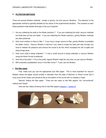
Membrane material Membranes may be composed of natural (e.g modifiednatural cellulose polymers ) or synthetic polymers (plasticmaterials) or inorganic ceramic materials 12be good film formers,manage high permeate flows,have high selectivity,have good chemical and bacteriological resistance,be resistant to detergents and disinfectants,be inexpensive.
Membrane material – cellulose acetate Mostly for RO and UF Advantages easy to manufacture, provide high flux and have high saltrejection properties Disadvantages 13limited temperature range (max 30 C),limited pH range (pH 3-6) – problem for cleaning withdetergentspoor resistance to chlorine as a sanitiser,poor membrane properties at high operating pressuressusceptibility to microbial attack due to their natural origin
Membrane material – synthetic polymers 14Polyamide and polysulphoneWidely used for UFWide tolerance to pH, temperature and chlorine
Membrane material – ceramic 15Made from mineral materials such as glass,aluminium oxide and zirconium oxideHigh resistance to chemical degradation, andtolerate wide pH and temperature rangesExpensive and can be brittleMainly used for microfiltration
Chemical resistance of membrane materialWagner, 2001, Membrane Filtration Handbook16
Membrane manufacturersWagner, 2001, Membrane Filtration Handbook17
Membrane modules 18Plate and frameSpiral woundTubular, based on polymersTubular, based on ceramicsHollow-fibre
Plate and frame design 19Membrane sandwiched between membranesupport plates which are arranged in stackssimilar to a plate heat exchangerTypically polymers (e.g polyethersulfone) withpolypropylene or polyolefin supportUF ( 1 to 1000 kDa MWCO)MF (0.1 to 0.16 um diameter)
Plate and frame membrane systemsRetentatePermeateFeedOval shapedRectangle shaped20
Plate and Frame moduleNirosoft waste water system21http://www.nirosoft.com/site/item.php?ln en&item id 189&main id 110
Plate and Frame moduleNirosoft waste water system22http://www.nirosoft.com/site/item.php?ln en&item id 189&main id 110
Spiral Wound membraneWagner, 2001, Membrane Filtration Handbook23
Spiral Wound membrane – cross-section24
Hollow fibre membrane Hollow-fibre a narrow tube made of anon-cellulosic polymerwww.norit.nl25
Hollow fibre membranewww.tifac.org.in26
Hollow fibre membrane27
Tubular design - polymers Stainless steel tubes in 28shell and tubeconstructionMembrane insertPCI – Patterson andCandy International
Tubular design - ceramic Channels fine-grained ceramic Support Coarse-grained ceramic Applications removal of bacteria frommilk, whey, WPC, brine French company - SCTDairy Processing Handbook29
Comparison of membrane modulesSystemAdvantagesFlat Sheet/ 1. Low hold up volumePlate and 2. Permeate from individualFramemembrane element3. Membrane replacement easyDisadvantages1. Difficult to clean2.Susceptible to pluggingSpiral1. Compact1.Not suitable for very viscous fluidWound2. Minimum energy consumption 2.Dead spaces3. Low capital/operating cost3. Difficult to clean4.Faulty membrane - change whole moduleHollowFibre1. Low hold up volume2. Backflushing possible3. Low energy consumption1. Susceptible to end-face fouling2. Not suitable for viscous fluids3. Single fibre damage - replace entire moduleTubular1. Feed stream with particulatematter can be put throughmembrane2. Easy to clean1. High energy consumption2. High hold-up volume30
Comparison of membrane modules31Wagner, 2001, Membrane Filtration Handbook
Filtration modulesRONFUFSpiral-wound Plate and frame Tubular (polymers) Tubular (ceramics) Hollow-fibre 32Dairy Processing HandbookMF
Membrane structure Asymmetric Same material throughout, but has a thin, tight skin on thesurface of the feed side so that the skin is the effective filtrationlayer, and the more open and thicker sub layer serves as asupport for the skinMost widely used for both UF and RO Same material with the same structure throughout A thin polymer membrane on a microporous sub layer ofanother material Symmetrical Composite asymmetric membranes33
Batch operationEnergy inefficient34
Continuous operation with single passNot practicalToo large area requirement35
Continuous operation feed and bleed36
Multistage operation37
Factors affecting membrane performance fouling Concentration polarisation Differential solute conc between membrane surface and bulk streamReversibly affected by operation parametersFouling Formation of deposits Irreversibly affected by operation parameters38
Concentration polarisation39
Membrane fouling Two types Surface (temporary) fouling Pore (permanent) fouling40
Membrane fouling Surface (temporary) fouling Foulant appears an evenly deposited layer on the 41membrane surfaceCan be easily removed by cleaning solutionPermeation rate of membrane can be regenerated bycleaningMost common type of fouling in UF plantMost studies dealt with this type of fouling
Membrane fouling Pore (permanent) fouling Particulate matter diffuses into the membrane Could be caused by the poor quality of the cleaning 42waterUneven distribution of the foulant and compression ofthe separation zoneFlux cannot be regenerated by cleaningDetermines the lifetime of the membraneReceived much less attention in literature
Membrane fouling Implications More energy consumption Duration of continuous operation without need for 43cleaningMembrane durabilityProperties and quality of concentrateOverall economy of the membrane process
Ultrafiltration 44Can be defined as a pressure-driven membraneprocess that can be used in separation andconcentration of substances having a molecularweight between 103 – 106 DaltonsMost widely used in dairy industry
Applications of UF in dairy industry Protein standardisationMilk solids fortification for yogurtCheese Whey protein concentrate and isolate (WPC/WPI) Milk protein concentrate and Isolate (MPC/MPI)45 Increased yield Protein concentration Protein concentration
Five fold concentration of milk by UFMilkComponent% Fat% Protein% Lactose% Salts% Total Solids% Water46Feed Retentate/Permeate100 L MilkConcentrate 20L 04.80.75.594.5
UF – Commercial UF plant set upDairy Processing Handbook47
WPC 48UF spiral-wound membrane MW cutoff: 10000 Da DF required for higher than 60% protein
Whey protein concentrate35-85% protein in dry matter 49UF : 25-30% solidsMF to remove fatDF to remove more lactose and mineralsSpray drying
WPI ( 90% protein) UF/DF Microfiltration to remove fat50
WPC manufacture51
WPC – Whey compositionTotal oferrin52Sweet wheypH:6.2-6.4Acid wheypH: 4.6-5.0
WPC To increase flux Demineralisation Calcium removal 53(electrodialysis)Sequestering agent (SHMP)Increase pH to 7.5 (calcium phosphateprecipitate)Preheating 60 C for 30 min; UF at 50 CMicrofiltration
Effect of diafiltration on Diluted50:50with water40L .020.00.0Protein%17.58.7517.50.0Lactose %4.82.42.42.4Salts0.70.350.350.35Total Solids%43.021.540.252.75Water57.078.558.7597.25%%
Modern WPC plantFeed flow – 100,000 L/h constant feed rateTemperature - cold55
Milk protein concentrate Concentrating both casein and whey proteinsRatio similar to milkApplications: Cheese milk extension Nutritional beverages56
MPC CompositionComponentsNFDMMPC-56 MPC 75MPC 80(% 21.51.7Lactose51.33110.95.5Minerals7.78.08.27.457
MPC Manufacturing ProcessPasteurization/UHTRaw ionCreamWaterUF/EV concentrateSkimmilkmilkSkimUltra/diafiltrationUF Concentrate58WaterPermeateSpray DryingMPCWater
UF in cheese making Protein standardisation 3.6-4.0% Consistent cheese quality Increased throughput Open structure cheeseModified equipment needed Suitable for closed structure cheeseModified equipment needed Pre-concentration – 2X Partial concentration 20% and 40% TS Total concentration59
Applications of UF in dairy industryDairy Processing Handbook60Tilsiter cheese using ultrafiltration
Reverse osmosis Osmosis Pure water flows from a dilute solution through asemipermeable membrane(water permeation only) to ahigher concentrated solutionRise in volume to equilibrate thepressure (osmotic Water
Reverse osmosis Reverse osmosis If pressure greater than the osmoticpressure is applied to the highconcentration the direction of waterflow through the membrane can bereversed.http://www.trionetics.com/an001.pdf62
Reverse osmosishttp://www.trionetics.com/an001.pdf63
Reverse osmosis 643-10 MPaRemove water against osmotic pressureΠ 0.7 MPaWater and small molecules diffuse through30% dry matter achievableGel layer formed by caseinWhey proteins at pH 6Calcium phosphate a problem at pH 6.6
Reverse osmosis Milk - Can be used for concentration up to 30% TS Fat globules increases viscosity Homogenization in retentate through the pressure 65release valveLactose crystallizationApplied to permeate from UF or whey
Whey powder - RO Separation of fat and casein fines Pasteurization Concentration Reverse osmosisVacuum evaporation (45-65%)(Lactose crystallization) Spray drying66
Nanofiltration (NF) 67New class of pressure-driven membraneprocesses that lies between UF and ROPressure range - 10-50 barRejects ions with more than one negative charge(such as SO42- , CO32-)
Nanofiltration Removal of inorganic salts Na, K, Cl, urea, lactic acid, Partial demineralization Membranes that leak particle species with a radius in thenanometer range 68Reduce salty tastePretreatment for electrodialysis, ion exchangeAcid removalReduce salt from cheese making
Lab NF equipment – DDS Lab 20 Plate & Framehttp://www.ivt.jku.at/Lehre/pdf2/04NF PRws2006.pdf69
NF -Salt rejection by different NF membranes - 0.2M NaClΔ - 0.2M Nasulphatehttp://www.ivt.jku.at/Lehre/pdf2/04NF PRws2006.pdf70
NF – rejection at 30 bar at 25CMW 200-1500 Da - 90% rejectedhttp://www.ivt.jku.at/Lehre/pdf2/04NF PRws2006.pdf71
NF - Commercial NF membraneshttp://www.ivt.jku.at/Lehre/pdf2/04NF PRws2006.pdf72
MF - Microfiltration 73Two filter modules connected in seriesOne retentate circulation pumpOne permeate circulation pump
MF – industrial two module MF system 74Dairy Processing HandbookTwo filter modulesconnected in seriesOne retentatecirculation pumpOne permeatecirculation pump
MF – Design principle of MF filter loopDairy Processing Handbook75
MF - Hollow fibre designA – filtrationB – Back flushingC - CleaningDairy Processing Handbook76
GEA Filtration77
MF - buttermilkMF (0.8 um) 50C; 25C; ¡7CJ Dairy Sci 2004, 87, 26778
MF - buttermilkMF using 0.8 um membraneJ Dairy Sci 2004, 87, 26779
Other membrane techniques 80Counter diffusionOsmotic distillationElectrodialysisIon-exchange
Counter diffusion81Separate small ions from large moleculesHollow fibre cellulose diffusion tubesCounter diffusion can produce 50% demineralisationwhich may represent 70% removal of monovalents
Osmotic distillationLow pressure and low temp separationHollow fibre or spiral wound hydrophobic membrane82
ElectrodialysisUses electrical force to separate charged particles83
Non-dairy uses of membrane technology 84Potable water desalination – ROSea water desalinationJuice processingWine processing
Cleaning, sanitation & storage of membrane CIP 85Flushing with water to remove loose dirt;Circulatory cleaning with a caustic detergent;Rinsing with water;Circulatory cleaning with acid detergent;Rinsing with water
Cleaning 86Factors affecting cleaning TemperaturepHTimeType of soilMembrane materialWater qualityModule designMechanics of cleaningTypes of cleaning agent
Sanitation and storage To minimise the bacterial attack Sodium hypochlorite Store in weak sodium hypochlorite, 5 ppm or sodiummetabisulphite at 0.1% (short term) or 0.25% (longterm)87
Typical cleaning procedureOperationAgentFeed pressure (Bar)InletOutletTemp CDuration(min)pH6012.61.Flushing until all product hasbeen removed2.Caustic cleaningWater/ROpermeate0.5%Ultrasil - 253.51.51-153.51.5753.Flushing out cleaning agent3.51.54.Acid cleaningWater/ROpermeate0.3%Ultrasil - 753.51.555202.35.Flushing out cleanin
Dairy Processing Handbook. 33 Membrane structure Asymmetric Same material throughout, but has a thin, tight skin on the surface of the feed side so that the skin is the effective filtration layer, and the more open and thicker sub layer serves as a support for the skin Most widely used for both UF and RO Symmetrical Same material with the same structure throughout .
