Transcription
Automatic ChessboardESE 350: Final ProjectSpring 2011Brian & JamesPage 1 of 16
Page 2 of 16
IntroductionThe purpose of this project was to create a physical chessboard that is able to interactwith a human player and a computer. The game begins when the player makes a move. Thecoordinates of the piece’s original location and its current location are fed into a computer chess engineafter being detected by sensors embedded in the chessboard. The computer then replies with its move,giving the piece’s current location and the desired destination. An XY positioning table underneaththe board moves to the location of the piece to be moved. A magnet is then raised to attract theabove piece and the piece is moved to the desired destination. The magnet is then lowered, and the XYpositioner returns to its origin at the center of the board to await the next human move.General Hardware DescriptionHardware and Parts List 1 Freescale HCS12 MC9S12C Microcontroller Board1 Freescale PBMCUSLK Development Board1 Serial cable1 USB cableCodeWarrior Development Studio for HCS12(X)Epoxy and glueWireFor the Detection Board: 64 Reed h/dksus.dll?lang en&site US&WT.z homepage link hp go button&KeyWords HE558-ND&x 0&y 064 1N4148 Diodes8 10kΩ resistors1 2’ by 2’ total punch board1 clear Plexiglas plastic sheet for the actual chessboard (2' x 2' x 1/4")32 (3” by 3”) Post-it notes for the squares1 ( 0.5”) diameter metal pipe16 small steel disks16 small weaker refrigerator magnets1 chess setFor the XY Table: 1 main very flat and heavy wood board to mount everything on (2' x 2' x 7/8")3 twenty-four inch Drawer Tracks: city/dp/B0000DD4AB/ref sr 1 1?ie UTF8&qid 1299258131&sr 8-11 ( 6’ x 4” x .5” ) piece of pine woodPage 3 of 16
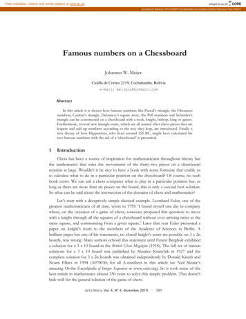
4 wood screws2 Bipolar Stepper Motors: http://www.pololu.com/catalog/product/12002 Stepper Motor Drivers: http://www.pololu.com/catalog/product/12011 servo motor2 one inch diameter gears: tion/276-2250.html2 sets of linear gears: http://www.vexrobotics.com/276-1957.html6 small Neodymium disc magnets: http://www.kjmagnetics.com/proddetail.asp?prod DB212 10kΩ resistorsDetection Board Hardware DescriptionThe detection chessboard consisted of a 2 foot by 2 foot, 0.25” inch clear plastic board that was placedon top of a 0.125” thick 2 foot by 2 foot punchboard. The chess pieces were placed on top of the plasticboard, and the electrical circuit elements and switches were placed on the punchboard. The result wasthat the circuit elements were sandwiched between the punchboard and plastic sheet, and not able tobe damaged by the magnet underneath. The magnet then had to be able to move pieces with metallicdisks attached to them through about 0.5” thickness of material.The choice of a 2 foot by 2 foot chessboard, which corresponds to 3” by 3” squares was made aftertesting four key things; the effectiveness of the six neodymium magnets connected together to movethe metal disks we chose through 0.5” of material, how close the metal disks could get to each otherwithout being attracted to each other when the magnet was attracting one of them was roughly 1.5”,and the distance from being attracted to the smaller weaker refrigerator magnets placed on thehuman’s chess pieces was also about 1.5”, the weak magnets were powerful enough to penetrate the0.25” of plastic board and trigger the magnetic reed switches however not too powerful that theywould trigger a neighboring reed switch 3” away. The metal disks were punched out from steel electricalboxes that you’d use in your home to wire light switches or other things, as shown in Figure 1.Figure 1: weak magnets and metal disks usedTo build the detection board we first started by gluing several smaller punchboards into one large 2 footby 2 foot punch board so that all the circuit elements and sensors could easily be mounted onto it. Theboard was then wired like a very large keypad. Eight independent column wires separated by 3” wereweaved parallel through the punchboard for the length of the punchboard. Also, eight independent rowwires separated by 3” were weaved parallel through the punchboard for the length of the punchboard,and perpendicular to the column wires. The 64 magnetic Reed switches were soldered exactly in thecenter of each 3 inch by 3 inch square. The Reed switches are normally open, meaning that they shortwhen a magnet is brought close to them. A 1N4148 diode was also connected to the row wires in seriesPage 4 of 16
with each of the switches. This was to make it so that we could have multiple closed switches at once,rather than only being able to only be able to close one switch at a time. Without the diodes, with threeor more pieces there would be ghosting and shorting of wires that not allow us to detect multiple chesspiece locations at once since the microcontroller is using an real time interrupt that successively sends asingle column high every 4ms. Thus there are no shorts of 5V to the row inputs from other columnswhen a single column was driven high because the diodes stop current flow in the wrong direction andact as open circuits. For more detail see http://www.dribin.org/dave/keyboard/one html/. We used1N4148 diodes because they have a faster switching time than 1N4004 diodes. The entire circuitdiagram can be seen in Figure 2. All 8 rows were connected to PORTAAll 8 columns (or each lettered column line “a” to “h” of a general chessboard) were connected tomicrocontroller output pins PB0 to PB7, and all 8 rows (or each horizontal numbered row) wereconnected to microcontroller input pins PA0 to PA7. We inserted 10kΩ pull-down resistors to groundfor stability, and so that the 5V input would not be directly shorted to the input. It is effectively a highasserting switch. For someone trying to save space on ports, we recommend using 3 bit multiplexers anddecoders so that you only need 6 total inputs and outputs to the board rather than 16.Figure 2: Detection Board Circuit DiagramHere is a photo of the wired board:Page 5 of 16
Figure 3: Fully wired detection boardIn order to support the board, help keep it from warping, and obtain full range of the XY position systemmetal poles were mounted on all four sides of the board. Finally, due to the wires being weaved to makethe columns and rows, it was necessary to tape printer paper of the thickness of three sheets to thebottom of the punchboard. This ensured the XY position magnet would not get caught on these wiresand break off. Also the magnet can then be pressed up flatly against the board to so that the board canstill be used even if it is warped. The finished detection board is shown in Figure 4.Figure 4: Finished Detection BoardAs a final note on the detection board, the human’s chess pieces have the weak refrigerator magnetsglued to the bottom of them, and the computer’s pieces have the metal disks glued to the bottomof them. This is because it is only necessary to detect the movement of the user’s pieces, not thecomputer’s pieces. In addition the human pieces could also therefore have sticky tack attached tothem since the XY positioner doesn’t need to move them and so that the strong neodymiummagnet on the XY positioner does not attract them.Page 6 of 16
Detection Board Software DescriptionA general chessboard’s layout is labeled as in the following diagram.This is therefore the type of coordinates that the computer chess algorithm that we found outputted.Thus we needed to perform some conversions to interface with the chess program. We needed toconvert the numerical move coordinates of the human’s chess momoveve detected by the detection boardinto a (letter, number) to (letter, number) coordinate.Recall that the circuit diagram for the detection board is shown in Figure 2. By successively driving asingle column line high,, and the other columns low, the microcontrollerocontroller could then read the input portsto see whether any of them are highhigh. A coincidence of a row and column line being high means that ahuman’s piece is occupying that particular square. If the input to the microcontroller is low when thecolumn is driven high, this means there is no piece on that particular square.The scanning of the column lines was done using a realreal-time interrupt. About 4 ms of low output wasspent on each column. Every 4 ms the RTI interrupt is called, and the next column is sent high. The nextcolumn to send high is determined by the variable rti cnt which ranges from 0 to 7. When rti cnt is 0this means column “a” (or 0 numerically), (corresponding to PB0) is low, when rti cnt is 1 this meanscolumn “b” (or 1) is low, etc.An 8 by 8 matrix stores the current state of the board. For example when the game first starts out theprogram will obtain the following board state matrix:{ {1, 1, 1, 1, 1, 1, 1, 1}{1, 1, 1, 1, 1, 1, 1, 1}{0, 0, 0, 0, 0, 0, 0, 0}{0, 0, 0, 0, 0, 0, 0, 0}{0, 0, 0, 0, 0, 0, 0, 0}{0, 0, 0, 0, 0, 0, 0, 0}{0, 0, 0, 0, 0, 0, 0, 0}{0, 0, 0, 0, 0, 0, 0, 0} }A '1' represents a piece has been detected, aand a '0' represents an empty square. Note only the player'spieces will be detected since the computer pieces do not have magnets on them. 64 bytes may seemsPage 7 of 16
like a waste of space when only 64 bits are needed, but C does not have a bool type and bitmanipulation can be difficult.Note that the state matrix won’t look exactly like the chessboard. It will look like a flipped mirroredimage because the matrix starts at (0,0) at the top left, whereas the chessboard starts at (A,1). This is ok,because the program just needs to extract the start coordinates and end coordinates of the piece thehuman moves. It will be a direct map from the board to this matrix.For example, say we move a pawn from C2 to C3 on the physical chessboard. The RTI system sees thisas moving from (1,2) to (2,2). Note that chess labeling is not (row, column) like matrix notation, it’s(column, row). The program will catch the change from 0 to 1 in the board state matrix at coordinate(1,2), (we incorporated some debouncing here). The program has a four character long string andchange the first two characters to “C2 “. Then the program will catch the change from 1 to 0 in theboard state matrix at coordinate (2,2), (again some debouncing). The character string will then beupdated to “C2C3”. This move of “C2C3” will then be passed into the computer program. The computerwill then output its move.The following is the correspondence table. The row number 1 corresponds to the second coordinate,whereas the column number corresponds to a letter which is the first coordinate:Figure 5: Converting Human Piece Moves to Computer InputLines 213 to 272 perform the human move detection in the main function. The accompanying functionsare getPositions(), arrayCopy(), and arrayCompare(). The getPositions() function is the function that goesthrough each of the 64 chess squares and writes a 1 if the Reed switch is closed (therefore a piecepresent) and otherwise a 0 for no piece present. This function relies upon the RTI to bit rotate PORTBand rti cnt to increase. The arrayCopy() function copies the contents of one 8x8 array to another 8x8array. This then later allows us to compare the present board state to a previous board state todetermine which square a piece moved from and to which square it went to. The arrayCompare()function essentially just compares two 8x8 arrays to see if they are different, so that we can see if ahuman made a move, and then where it went to. It takes the address of two arrays. Then column bycolumn, row by row each element is compared. If there are no differences then 0 is returned, otherwise1 is returned and the two variables at the memory address of Xchange and Ychange are changed toreflect the difference.After the start and destination coordinates are obtained they are output through serial as the human’smove.Page 8 of 16
XY Table Hardware DescriptionThe XY table positioner needed a very flat and heavy base on which to mount everything. We chose arelatively cheap particle board that was 2' x 2' x 7/8", which looked like it might be used on acountertop. The first step was to mount two drawer tracks exactly parallel to each other, one on eachside of the board. These tracks serve as the X-axis direction of motion, and they had to be perfectlyparallel. If the bottom tracks are not mounted perfectly parallel, the stepper motor would only be ableto move in the X-axis direction a limited distance before stopping at some arbitrary location instead ofgoing the full two feet desired range of motion.Next, the circular gears were glued onto the stepper motors, which involved drilling a hole through thegears that was large enough so that the gear would fit the axle. Then, linear gears were glued onto a 2foot long piece of pine wood in a perfectly straight line, and the wood was glued right next to the track.This effectively raised the linear gears up because the 1” circular gear was too small to reach the gears ifthey were glued directly on the flat board next to the drawer rack. Thus after this, the motor had to bemounted at a specific height using an 8 inch piece of the pine wood and then the pine wood glued ontothe track with the circular gear mated with the linear gear. This was tedious as the gear needed to beable to run along the entire length of the two feet of linear gears. After this another 8 inch piece of pinewood needed to be mounted in the same place on the track directly across from the first support. Thesetwo pieces of wood will then serve to support the Y-axis motor. Here is a photo of the X-axis motormounted. Note that the linear gears are not glued in place yet, but the glue is still drying:Figure 6: X-axis of the XY tableThe next step was to mount the Y-axis drawer track. First a two foot piece of pine was mounted directly on top ofthe 8 inch pine supports shown in Figure 6. It was mounted with 4 wood screws so that it was perfectlyperpendicular to the X-axis drawer tracks. Then, one drawer track was mounted on this piece of wood. Then,similar to the X-axis, linear gears were raised and placed on a two foot long piece of pine wood and placed directlyPage 9 of 16
along the drawer track. The Y-axis motor was also mounted on another 8 inch board to raise the motor to have thecircular gear mate with the linear gears. This motor was not mounted as stable as the X-axis motor due to the lackof a cross support, so a counterweight was needed on the pine wood to help the gear stay in contact with thelinear gears. Note that the motors were mounted in the same direction such that we could have an intuitivepositive direction in the X-axis and Y-axis corresponding to the same rotation direction of the motor axles.The next step was to mount the servo motor that would flip up the magnet. The servo was placed very close to theY-axis stepper motor so that we could get the full range of motion from the entire system. Then the magnet wasglued to one end of a wooden dowel rod that was about 6 inches long. This dowel rod was then glued to the servomotor when it was in the raised position so that we could make it be perfectly flat facing upward when in the onposition. The dowel rod had to be this long because the magnet needed to be at least 4 inches away from theboard when it was lowered so that it wouldn’t trigger any Reed switches when the board was to detecting moves.This then completes the construction of the XY table. It was rather tedious to build, and I recommend anyone thatis building one to take their time to get all the measurements exactly correct so that you won’t have to end uptaking it apart and rebuild it. We were pretty lucky in that itworked perfectly after the first try of building it.Figure 7: Completed XY TableThe final part of construction on the XY table involved wiring up the stepper motors. A motor driver wasneeded for each stepper motor.Figure 8: Stepper Motor DriverPage 10 of 16
The motor we chose can be either unipolar or bipolar and has 6 leads. We chose to use it as bipolarsince it only required the use of four of the leads. Bipolar steppers have a single coil per phase. Thethree inputs we had that were controlled by the microcontroller were DIR, STEP, and . The DIRdetermines the direction of rotation of the motor. When low, the direction will be clockwise and whenhigh, counterclockwise. A low-to-high transition on the STEP input sequences the translator andadvances the motor one increment. The size of the increment is determined by the combined state ofinputs MS1, MS2, and MS3. We tied MS1 to high (5V) to get half-steps. The Sleep input minimizespower consumption when the motor is not on. It was necessary to use this because the motors draw 1to 1.2A constantly if they are not disabled. If left on, the drivers could become overheated and burn.This happened to one of our drivers, and luckily we had an extra one.The VMOT input controls the voltage and current input to the motor. The motors were rated at 4V and1.2A. The minimum voltage needed by the board at VMOT is 8V. For stepper motors, the voltage is notas important as the current, so we could set this to 8V with no problem. However, the current limit tothe motors had to be set. The driver has a built in current limiter that can be changed for different sizemotors. There is a small circular Vref pin in the center of the driver board. If everything is connected upcorrectly and the logical voltage and motor voltage is applied, this voltage can be measured. The currentlimit is then Vref/(8*.05). The value of Vref can be changed by adjusting the potentiometer on the backof the board with a screwdriver. The current limit was adjusted to 1.2A for these motors. The enable pin was constantly tied to ground so that the motors would stay enabled. Also, the reset was tied to 5V so that the motor wouldn’t reset. VDD was the logic voltage and had to be tied to5V. The entire circuit is shown in Figure 9.Figure 9: Stepper and Servo Motor WiringPage 11 of 16
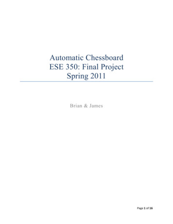
The blue wire of the stepper was connected to 2B, the red wire to 2A, the black wire to 1A, and thegreen wire to 1B. PT2 and PT5 of the microcontroller were utilized as output compare to control the Xaxis step and Y-axis step respectively. PT3, PT4, PT6, and PT7 were used as GPIO output pins to controlDIR and since all of PORTA and PORTB were used by the detection board.Figure 9 also contains the wiring for the servo motor as well. We used PP0 as input to the servo, which isa pulse-width modulation port.XY Table Software DescriptionLines 273 to 456 control the XY table movements of the computer’s move. The segment of the codedealing with XY table movement begins with the getMove() function on line 273. This function obtainsthe computer’s move over serial and places it in a length 4 array called computerMove.We needed to have another conversion of coordinates to be able to interface the XY table movementwith the computer’s coordinate outputs. We needed to convert the computer’s letter, numbercoordinates to numerical coordinates for the XY table to perform its task.The moves will come in the form (letter,number,letter,number). For example a move could be C7C6,which would mean move the piece at square C7 to square C6. Again recall that the computer outputs in(column, row) coordinates instead of matrix coordinates (row, column). Thus we do an inversecoordinate transform as that shown in Figure 5 to get the correct numerical coordinates. Thus C7 wouldcorrespond to (6,2), and C6 would correspond to (5,2).We designed the XY magnet system so that it can transport the pieces along the lines in between thesquares so that the pieces do not collide. This is another reason why the board squares needed to be alarge 3” by 3”. Thus the XY magnet system needed to have a finer coordinate system so that it can bothgo to the location of the piece and go in between other pieces. The following grid shows the coordinatesystem of the XY magnet system.Figure 10: XY Positioner Coordinate SystemPage 12 of 16
The coordinates now range from 0 to 16 in both X and Y directions. The actual chess squares are coloredso that the coordinate system can be visualized overlaying the actual chessboard. The chess pieces canonly be located at coordinates where both the X and Y coordinates are both odd.Note that the transformed numerical move coordinates will again need to be changed to fit thegranularity of the XY system coordinate system. This involves multiplying each coordinate by two andadding 1: (2x 1,2y 1). Thus if the instructions are move piece at (6,2) to space (5,2) are received, thiswould correspond to the XY system needing to move the piece at (13,5) to (11, 5). This is done on lines277 to 280.The XY system starts at the center of the board at the start of each computer move, which is position(8,8). The XY system is then returned to (8,8) after each move so that it can maintain a constantreference point. Luckily the stepper motors are extremely accurate and no recalibration was needed toprevent error. Even after moving a piece from one corner of the board to the opposite corner, themotors would return back to the exact center after completion.So when the origin coordinates are received, we subtract (8,8) from the coordinates. For example, (13,5)– (8,8) (5,-3). The X stepper motor then shifts up five coordinate steps; each coordinate step of 1.5”has a specified number of motor steps that was determined through testing. The number of steps is 255and defined as SET COUNT X and SET COUNT Y just in case the X-axis and Y-axis motors happened tobe different, but they weren’t. The Y stepper motor then shifts left 3 coordinate steps.Note that the stepping is done using the stepSpace(motorselect,numsteps) function. This function stepseither the X or Y axis stepper motor the distance of numsteps coordinate steps (each coordinate step is1.5 inches). The direction is changed accordingly if numsteps is negative or positive. WhenmotorSelect 0, the X-axis motor will step. When motorSelect 1, the Y-axis motor will step. Whennumsteps 0 then DIR 0; the direction is clockwise (set PT3 or PT6 to 0). When numsteps 0 then DIR 1;the direction is counterclockwise (set PT3 or PT6 to 1). The corresponding motorselect motor is firstwoken up, the motor then turns the specified number of turns corresponding to the value of numsteps,and then it is put back to sleep.After the XY magnet positioner arrives to the start coordinates, the magnet is then flipped up with theservo motor to attract the piece (line 299). Some delay ensures that the magnet has time to attract thepiece.Then the current coordinates are subtracted from the next coordinates. For example, (11,5) – (13,5) (2,0). Thus the X stepper motor will need to shift down 2 coordinate steps. The Y stepper motor will notneed to shift in this case. However, to avoid piece collision we want to travel along the lines instead ofthrough the squares. Thus, each time we are moving a piece, we first shift up and right 1 coordinatestep. So we’d go from (13,5) to (14,6). Then we’d do the (-2,0) shift, thus going from (14,6) to (12,6).Then we’d cancel out the offset shift by going down and left one coordinate, thus going from (12,6) to(11,5). The piece has then arrived at the destination coordinates.Page 13 of 16
Lines 309 to 351 take care of the offset. For most coordinates we simply apply the generic offset as justexplained, so that it is no longer centered on the square but on the grid line. The piece is then moved towherever it needs to go. This is not the shortest route but it does get the piece there. However, sinceour board has a metal pipe border we could not have the magnet anywhere near the border, as it wouldget attracted to the pipe and the range of motion can’t go beyond the border anyway. Thus a lot of thecode in lines 309 adds exceptions to certain moves. For example, if we want to move a piece from thetop row, we now shift down instead of up when offsetting initially. And, if the destination is a bottomsquare on the right side of the board, we shift in from the top left or bottom left of the square instead ofthe top right.To finish the move, the magnet is flipped down, and the stepper motors move the system back to thecenter (8,8) coordinate by subtracting the current coordinates from (8,8). For example, (8,8) – (11,5) (3, 3). The loop then starts over again and the computer then waits for the next human movement on thedetection boardChess Algorithm Software DescriptionThe chess engine communicates to the MCU via a RS232 interface (serial port). The chess engine runs ona computer and is fed chess moves via coordinates (C3C4), the engine replies to these moves bygenerating its own move and outputting its own coordinates. Originally, the engine sent and receiveddata from the terminal, however to interface with the MCU we needed an easy and compatible methodof communication.There was a simple library for serial communication included with the IDE for the MCU, so we decided touse serial communication. That meant that the computer chess engine written in C would need to bemodified to send and receive data over serial. By incorporating a PC serial library we were able to dothis. Since the library was initially intended for a windows or Linux environment a few modifications hadto occur.When the computer chess engine is waiting for user input it, it actually waits for data to be receivedover serial. The program takes the first four bytes (four characters for the coordinates) of the serialbuffer and interprets these as a move. The chess engine outputs its moves.ConclusionBy the end we had accomplished all that we set out to do; build a chessboard that can play physicalchess against a computer. The result was that it had the look and feel of playing against an actualopponent in real life rather than playing a computer game on the computer. There were some smallproblems that we could have fixed with more time. The metal disks we chose for the computer’s pieceswere a little bit too big, and sometimes when the magnet was moving in between the other computerpieces they would attract and either switch pieces or drag multiple pieces at once. This effect wassomewhat alleviated by putting some cardboard “bumpers” on each of the pieces in order to stop aPage 14 of 16
strong attraction. Also, the board we used to place the pieces on was not perfectly flat. Therefore someparts of the board, particularly the edges, were higher and the magnet sometimes couldn’t attract andmove these pieces. Another problem was that the human pieces couldn’t be placed directly in thecenter of the Reed switches because at that location for some reason the Reed switch wouldn’t close.Thus the piece had to be placed slightly off-center. The result was that sometimes if the human didn’tplace it correctly the computer wouldn’t register a move taking place and the program would say illegalmove. We didn’t program a back button, so every time an illegal move occurred we would have torestart the entire program. In addition, we didn’t have the capability to castle. At one point thecomputer tried to castle, and we just had to help it by moving the rook to the other side of the king forit. If we were to re-design the program we could make it so that if the king moves as if to castle, wewould also pick up the corresponding rook and move it to the other side. Finally, the biggest problemwas combining the detection board together with the XY table. This was difficult because the board hadto be mounted at a specific height above the XY table magnet so that the magnet was flush against thebottom of the detection board. You can see from the photos that we used some chairs to prop it up onsince they were adjustable to any height. The result is that it takes a while to get the board alignedcorrectly, but after that it works great as long as nothing moves.We are proud of our accomplishment of finishing a complicated and very lengthy project in such ashort amount of time. At many points throughout the project we were uncertain that it would everbe possible to do this. We thought it was very interesting that we used a lot of the subjects welearned in the labs to complete this project, and the whole project used the HCS12.Please see the videos on our blog at: www.acboard.blogspot.comOur final Demo video: http://youtu.be/2r53uC6XEgA(it was too large to upload to the file)The code (for both the hcs12 and chess algorithm) is in the same folder as this reportOur presentation slides.Figure 11: The Finished ProjectPage 15 of 16
ReferencesFor figuring out how to get multiple key presses: http://www.dribin.org/dave/keyboard/one html/.We used this website for some initial guidance on how to build the XY table. From this we got the ideaof using drawer tracks on a flat board in combination with the linear and circular gears to get the X-Ymotion, and a servo for a z-axis. We also got the idea of using a computer to play chess against but wedidn’t use or even look at any of the code on this website at all. We made all the code ourselves. And,everything else we did was different. duinoPowered-Chess-Playing-Robo/The stepper motor driver 3 DMOS microstepping driver with translator.pdf?file id 0J199Page 16 of 16
16 small weaker refrigerator magnets . 6 small Neodymium disc magnets: . To build the detection board we first started by gluing