Transcription
Water Wash Hood,Dry Grease ExtractorMaintenanceManual 2002Spring Air Systems Inc., Oakville, OntarioPhone (905) 338-2999, Fax (905) 338-0179, info@springairsystems.comwww.springairsystems.com
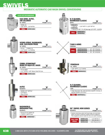
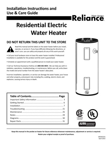
Water Wash HoodDry ExtractorOPERATING AND MAINTENANCE MANUALINTRODUCTIONThank you for selecting a SPRING AIR SYSTEMS INC. commercial exhaust water wash grease extractor. Your systemconsists of a water wash hood hood, a water wash control panel and plumbing box, an exhaust fan and make air unit.Others may have supplied the exhaust fan and make up air unit.SPRING AIR commercial kitchen hoods have been designed and constructed in accordance with the National BuildingCode, the National Fire Protection Association (NFPA-96), and listed by Underwriters Laboratories of Canada andUnderwriters Laboratories Inc. In addition the SPRING AIR SYSTEMS hood will meet all municipal code requirements.Each SPRING AIR hood is individually constructed to suit the space limitations of your commercial kitchen. The SPRINGAIR hoods are fabricated from No. 4 finish stainless steel with all the edges ground and polished. All hoods aremanufactured to stringent quality standards and are guaranteed to enhance the appearance of any commercial kitchen.Model HT-B Water wash Hood and model MP10H-19 Control PanelFigure 1The exhaust fan operation is controlled by a selector switch on the control panel or automatically by an electronicmicroprocessor based, 24-hour timer. Each time the exhaust fan is turned off the internal grease extractor portion of thehood hood is washed with a detergent and hot water mixture.The SPRING AIR water wash grease extractor was designed to best meet the needs of your commercial kitchen. TheSPRING AIR hood (hood) provides the following important benefits:1.Maximum Grease Extraction.2.Automatic Daily Wash.3.Second Line Fire Protection.4.Minimum Exhaust Requirements.Please read the manual carefully to familiarize yourself with your water wash hood. A factory trained service technicianwill complete a startup of your system. A copy of the start up report is available upon request.Each hood and control panel is described in detail. Refer to the UL/ ULC plate on your hood and water wash control panelfor your model numbers before proceeding.MODEL NUMBER DESIGNATIONS - HOODSA well-designed commercial kitchen ventilation system must consider proper ventilation, superior grease collection, anddaily cleaning and second line fire protection.Spring Air Systems Water Wash Hood Maintenance Manual 20021
There exist numerous types, styles and arrangements of SPRING AIR SYSTEMS hoods that meet these designrequirements. Refer to the ULC label for the complete model number of your hood. The ULC label is located on theunderside of the grease trough on the right hand side of the hood.SPRING AIR SYSTEMS HOOD MODEL NUMBER DESIGNATIONSHCHDCold water spray/hot water washHot water washDry Grease ExtractorTFDThermostatic Fire DamperFusible link, spring loaded fire damperFusible link, dead weight fire damperSBBSDBShelf type hoodBox type hoodBox shelf type hoodDouble box type hoodMGMPMIFMake up air through front grillesMake up air through perforated panelsMake up air internallySingle row canopy finished on all sides, RevLow type104The length of the hood in feetThe width of the hood in feetTBMP10C194Model Number Designation - HoodsChart No1MODEL NUMBER DESIGNATIONS - CONTROL PANELSAAMSAutomatic stop/start with time clockManual stop/startSingle sequence small panelPBBALarge size plumbing boxSmall size plumbing boxSmall size plumbing box with time clock1020304050One sequenceTwo sequenceThree sequenceFour sequenceFive sequenceCHCold water spray/hot water washHot water wash19Diameter of inlet to panel in mmP10Model Number Designation - Control PanelsChart No.2An integral part of any SPRING AIR SYSTEMS water wash hood is the water wash control panel. The water wash controlpanel controls the exhaust fan operation the daily wash and second line fire protection system.Spring Air Systems Water Wash Hood Maintenance Manual 20022
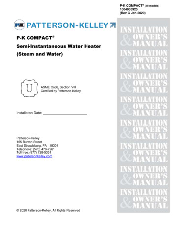
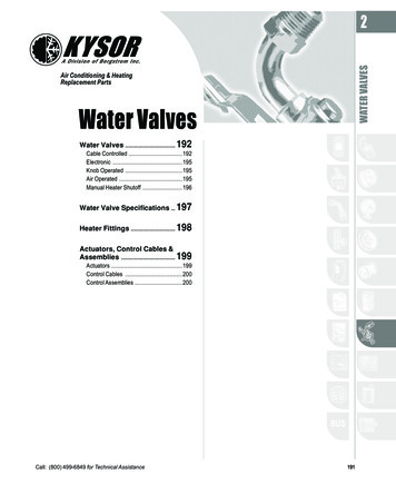
CONTROL PANEL OPERATIONSequence of Operation: All panelsExhaust fan: To start the exhaust fan rotate the fan selector switch to the “ON” position. The green “FAN ON” pilot andexhaust fan will turn on. The exhaust fan starter coil is energized through terminals 3 and 4 in the water wash controlpanel.Supply fan: Power is provided for a fresh air motorized shut offdamper through terminals 4, 8, & 9. The damper motor is energizedthrough terminals 4, & 8. Once an end switch closes 120V/1/60power is supplied back to the control panel through terminal 9. Thesupply fan motor starter is then energized through terminals 4 & 9.When a motorized damper with end switch is not used in theinstallation the field electrician must jumper terminals 8 & 9 in thewater wash panel to provide 120V/1/60 power to the supply fan motorstarter.MP10C & MP10H Wash PanelFigure 2Cold Water Spray Panels (SB10C/MPx0C/APx0C)When the fan selector switch is rotated to the “ON” position the cold water spray solenoid valve is energized. The coldwater spray operates while the exhaust fan is operating. The cold-water spray can be observed by looking into the inletslot of the grease extractor. All nozzles should be spraying to form a uniformed water pattern along the length of thehood.To stop the exhaust and supply fan rotate the selector switch to the “OFF” position. The green fan “ON” pilot and theexhaust fan will turn off.Cold Water Spray Panels (SB10C/MPx0C/APx0C).In addition the cold-water spray solenoid valve will close.SINGLE SEQUENCE WASHMODEL: SB10C, SB10HCAPACITY:One ¾” (19 mm) to 1.25” (32 mm) hot water inlet and one ¾” (19 mm) to 1.25” (32 mm) hot water outlet connections forwashing p to 46 ft. (14 m) of hood.Model SB10C and SB10H control panel internal wiringFigure 3MODELS: MP10C, MP10HCAPACITY:One ¾” (19 mm) to 1.5” (38 mm) hot water inlet and one ¾” (19 mm) to 1.5” (38 mm) hot water outlet connections forwashing up to 50 ft. (15 m) of hood.Spring Air Systems Water Wash Hood Maintenance Manual 20023
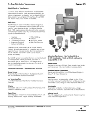
When the selector switch has been rotated to the “OFF” position, after a 60 second time delay, the blue “WASH” pilot thedetergent pump and hot water solenoid valve are energized. The hot water and detergent mixture flow to the hood andenter the grease extractor through an inlet pipe connected to the spray manifold. The detergent water mixture is sprayedfrom nozzles spaced uniformly along the length of the wash manifold washing the grease dirt and lint from the greaseextractor baffle and into the drain.The wash continues for the period of time set on the wash timer adjustable from 0 to 600 seconds. At the end of the washcycle the blue “WASH” pilot, the detergent pump and the hot water solenoid valve shut off. The system remains idle untilthe next time the fan selector switch is turned to the “ON” position.Single Sequence Wash MP10C & MP10H Electrical WiringFigure 4TWO SEQUENCE WASHMODELS: MP20C, MP20HCAPACITY: One ¾” (19 mm to 1.5” (38 mm) hot water inlet and two ¾” (19 mm) to 1.5” (38 mm) hot water outletconnections for washing up to 100 ft. (30 m) of hood.When the fan selector switch has been rotated tothe “OFF” position, after a 60 second delay, the blue“WASH #1” pilot, the detergent pump, and the hotwater solenoid #1 are energized.The detergent and water mixture washes the firstgroup of hoods (up to 50-ft. (15 m)). The washcycle remains on for the length of time set on washtimer #1 (T1) adjustable from 0 to 600 seconds. Atthe end of wash cycle #1 the “WASH #1” pilot andthe hot water solenoid #1 shut off and the blue“WASH #2”MP20C & MP20H water wash panelFigure 5Spring Air Systems Water Wash Hood Maintenance Manual 20024
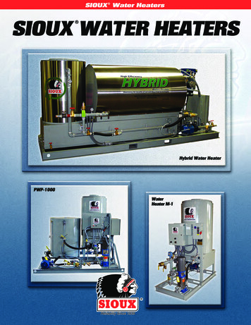
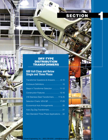
pilot and hot water solenoid valve #2 is energized. The detergent and water mixture washes the second group of hoods(up to 50 ft. (15 m)). The wash cycle continues for the length of time set on wash timer #2 (T2) adjustable from 0 to 600seconds. At the end of wash cycle #2 the “WASH #2” pilot detergent pump and hot water solenoid valve #2 shut off. Thesystem remains idle until the next time the fan selector switch is turned to the “ON” position.INTERNAL WIRING BY SPRING AIRCURCUIT BREAKERREMOTE WIRING BY TRADESFIRE TESTPUMP TESTFAN SWITCHOFF/AUTO/ON1o o x14POWER SUPPLY TO THE AP10H/C PANEL24 HOURS/DAY - 120V/1/60 - 15 AMPS34POWER TO THE EXHAUST FAN MOTOR STARTER120V/1/60 - 2 AMPS MAXIMUM.ORPOWER TO THE SPRING AIR SYSTEMS ENVIRO FILTER UNITLV10 PANEL - 120V/1/60 - 2 AMPS MAXIMUM.49(OPTIONAL) POWER SUPPLY TO SUPPLY FANMOTOR STARTER - 120V/1/60 - 2 AMPS MAXIMUM489(OPTIONAL) THREE (3) WIRES TO SUPPLY AIR MOTORIZEDSHUTOFF DAMPER AND END SWITCH 120V/1/602 AMPS MAXIMUM.410POWER TO SHUNT TRIP TO DE-ACTIVATE ELECTRICCOOKING EQUIPMENT IN THE EVENT OF A FIRE120V/1/60 - 2 AMPS MAXIMUM. (SHUNT TRIP ORRELAY SUPPLIED AND INSTALLED BY ELECTRICAL DIVISION)1o x x2x x o53LNI1I2I3I4I54I64I: 1 2 3 4 5 6Mo 09:00Q: 1 2 3 4 RUN48SMART RELAYQ1ESCQ2OKQ39Q410CFAN PILOTG5WHITE1REDNORMALLY OPENEND SWITCHTWO (2) WIRES TO THEWET CHEMICAL CONTROLHEAD 120V/1/60 - 1A.OPTIONAL COLDWATER SOLENOIDDETERGENTPUMPREMOTE WIRING FOR ARRANGEMENT "F" & "T" TYPE FIRE DAMPER HOODSONLY. ARRANGEMENT "D" FIRE DAMPER HOODS REQUIRES NO REMOTE WIRING.HBWASH PILOT1DAMPER END SWITCH2ENSHOT WATER SOLENOIDARRANGEMENT "F" FIRE DAMPERS:TWO (2) WIRES TO EACH ENS ENCLOSURE LOCATEDAT EACH EXHAUST DUCT COLLAR ON EVERY HOOD120V/1/60 - 1 AMPS. WIRE EACH ENS IN PARALLEL.1FENWALL DETECTOR24DAMPER SOLENOIDSOEORARRANGEMENT "T" FIRE DAMPER:THREE (3) WIRES TO EACH SOE ENCLOSURE LOCATEDAT EACH EXHAUST DUCT COLLAR ON EVERY HOOD120V/1/60 - 3 AMPS - WIRE EACH SOE IN PARALLEL.Two Sequence Wash Panel Model AP10C & AP10H Electrical WiringFigure 6THREE SEQUENCE WASHMODELS: MP30C, MP30HCAPACITYOne ¾” (19 mm) to 1.5” (38 mm) hot water inlet and one ¾” (19mm) to 1.5” (38 mm) hot water outlet connection piped to three¾” (19 mm)to 1.5” (38 mm) hot water connections to threegroups of hoods for washing up to 150 ft. (45 m) of hoods.When the fan selector switch has been rotated to the “OFF”position, after a 60 second time delay, the blue “WASH #1” pilot, thedetergent pump, and the hot water solenoid #1 are energized.MP10C & MP10H Water Wash PanelFigure 7Three sequence control panels have remote hot water solenoid valves. A 120/1/60 signal is supplied to each hot watersolenoid valve through terminals H1, H2, H3, and 4 in the control panel.TerminalsComponentH1 & 4Hot water solenoid valve #1H2 & 4Hot water solenoid valve #2H3 & 4Hot water solenoid valve #3Spring Air Systems Water Wash Hood Maintenance Manual 20025
INTERNAL WIRING BY SPRING AIRCURCUIT BREAKERFIRE TESTREMOTE WIRING BY TRADESALL HOT WATER SOLENOID VALVESARE LOCATED REMOTE FROM PANELPUMP TESTFAN SWITCHOFF/AUTO/ON1o o xPOWER SUPPLY TO THE AP20H/C PANEL24 HOURS/DAY - 120V/1/60 - 15 AMPS34POWER TO THE EXHAUST FAN MOTOR STARTER120V/1/60 - 2 AMPS MAXIMUM.ORPOWER TO THE SPRING AIR SYSTEMS ENVIRO FILTER UNITLV10 PANEL - 120V/1/60 - 2 AMPS MAXIMUM.49(OPTIONAL) POWER SUPPLY TO SUPPLY FANMOTOR STARTER - 120V/1/60 - 2 AMPS MAXIMUM489(OPTIONAL) THREE (3) WIRES TO SUPPLY AIR MOTORIZEDSHUTOFF DAMPER AND END SWITCH 120V/1/602 AMPS MAXIMUM.410POWER TO SHUNT TRIP TO DE-ACTIVATE ELECTRICCOOKING EQUIPMENT IN THE EVENT OF A FIRE120V/1/60 - 2 AMPS MAXIMUM. (SHUNT TRIP ORRELAY SUPPLIED AND INSTALLED BY ELECTRICAL DIVISION)2x x o5R5Set clockand lengthof firstwash here.B01 WASH1B04 CLOCK141o x x3LI1NI2I3I4I5I64I: 1 2 3 4 5 6Mo 09:00Q: 1 2 3 4 RUN4R5SMART RMALLY OPENEND SWITCHHOT WATER SOLENOID #1H1BFAN PILOTCTWO (2) WIRES TO THEWET CHEMICAL CONTROLHEAD 120V/1/60 - 1A.WASH PILOT #1REMOTE WIRING FOR ARRANGEMENT "F" & "T" TYPE FIRE DAMPER HOODSONLY. ARRANGEMENT "D" FIRE DAMPER HOODS REQUIRES NO REMOTE WIRING.GOPTIONAL COLDWATER SOLENOIDARRANGEMENT "F" FIRE DAMPERS:1DAMPER END SWITCHTWO (2) WIRES TO EACH ENS ENCLOSURE LOCATEDAT EACH EXHAUST DUCT COLLAR ON EVERY HOOD120V/1/60 - 1 AMPS. WIRE EACH ENS IN PARALLEL.2Set lengthof secondand thirdwash here.B02 WASH2B03 WASH3LNI1I2I3I4I5ORI6I: 1 2 3 4 5 61FENWALL DETECTOR2Q: 1 2 3 4 RUNSMART RELAYQ1Q2ESCQ3H2ARRANGEMENT "T" FIRE DAMPER:THREE (3) WIRES TO EACH SOE ENCLOSURE LOCATEDAT EACH EXHAUST DUCT COLLAR ON EVERY HOOD120V/1/60 - 3 AMPS - WIRE EACH SOE IN PARALLEL.4OKQ4HOT WATER SOLENOID #2BH3DAMPER SOLENOIDWASH PILOT #2HOT WATER SOLENOID #3BWASH PILOT #3Three Sequence Wash Panel Models AP30C and AP30H ElectricalFigure 8The detergent water mixture washes the first group of hoods (up to 50-ft. (15m)). The wash cycle continues for the lengthof time set on wash timer #1 (T1), adjustable from 0 to 600 seconds. At the end of wash cycle #1 the blue WASH #1” pilotand the hot water solenoid valve #1 shut off and the blue “WASH #2” pilot and hot water solenoid valve #2 energize. Thedetergent and water mixture washes the second group of hoods (up to 50 ft. (15m)). The wash cycle continues for thelength of time set on wash timer #2, adjustable from 0 to 600 seconds. At the end of wash cycle #2 the blue “WASH #2”pilot and the hot water solenoid valve #2 shut off and the blue “WASH #3” pilot and the hot water solenoid valve #3energize. The detergent water mixture washes the third group of hoods (also up to 50 ft. (15 m)). At the end of washcycle #3 the blue “WASH #3” pilot the hot water solenoid valve #3 and the detergent pump shut off. The system remainsidle until the next time the fan selector switch is rotated to “ON” position.FOUR AND FIVE SEQUENCE WASH SYSTEMSFour and five sequence wash control panels operate similarlyto the three-sequence wash. After the third wash cycle iscomplete the system proceeds to the fourth and fifth washcycles.Due to space limitations within the kitchen the four and fivesequence wash system also have remote solenoid valves.The detergent pump and tank are still located in the washcontrol panel. See wiring and piping diagrams in the back ofthe manual for the four and five sequence wash systems.MP4
Each SPRING AIR hood is individually constructed to suit the space limitations of your commercial kitchen. The SPRING AIR hoods are fabricated from No. 4 finish stainless steel with all the edges ground and polished. All hoods are manufactured to stringent quality standards and are guaranteed to enhance the appearance of any commercial kitchen. Model HT-B Water wash Hood and model