Transcription
Study guide toUltrasound Physics Registry ReviewMelessa Cizik RDMS, RVTwww.myultrasoundtutor.com2020 edition
Table of ContentsPhysics principlesProperties of sound . . .1Properties of the medium . .3Sound propagation in tissue . . 4Resolution 8TransducersConstruction and function . .11Types . . 13Imaging Principles and InstrumentationPulse-echo principle and modes. .17Image processing and Instrumentation . . .18Harmonics. 24Artifacts . 25Doppler and HemodynamicsDoppler principles and Instrumentation . 28Hemodynamics 34Safety and Quality AssuranceBioeffects and safety . 39Quality Assurance . 41New technologies . 43
Ultrasound Physics ReviewPhysics principles (15%)Properties of soundSound is a mechanical, longitudinal wave. Longitudinal means parallel from soundsource. Mechanically moves through medium by vibration of molecules or physicallychanging pressure, compressions (high pressure) and rarefactions (low pressure)One complete cycle 1 compression and 1 rarefactionFrequencyWavelengthPeriod# cycles per second Hzlength of one cycle mmtime of one cycle µsƛ cfƛ wavelengthc prop speedf frequencyRelationshipsDirect: If one increases, the other increases and vice versa (go together)Inverse: If one increases, the other decreases (opposites)Wavelength depends on 2 things - frequency (determined sound source)and propagation speed (determined by medium)Wavelength and frequency are inversely relatedWavelength directly related to propagation speedMediums with fast prop speed longer wavelengthMediums with slower prop speed shorter wavelengthPropagation speed is NOT affected by either freq or wavelengthThink about the terms! Physics is very literal. If you do not know what something means, think aboutwhat it means in everyday language.Example: frequency means how often something happens in a period of time. So in ultrasound, itmeans how many waves occur in one secondDifferent types of sound Infrasound 20 HzAudible sound 20-20,000 HzUltrasound 20,000 HzDiagnostic US2-20 MHzCommon unit pre xeskila(k) thousandmega(M) millioncenti(c) 1/100milli(m) 1/1,000micro(µ) 1/1,000,000Simply exchange the word with the pre xExample: 20,000 Hz 20kHzfifiNot for Distribution1
Ultrasound Physics ReviewMeasuring energyPower- rate of ow of energy (Watts)Intensity- power/area (Watts/cm²)Example: 40 Watt light bulb. That’s power. Imagine the 40W bulb in a small closet vs it in alarge room. Which appears more intense? The closet smaller space greater intensity.Increase the space decreases the intensityAmplitude- height of pressure wave (MPa megapascals). Hydrophone: used to measure thepro le of US beam by measuring the pressure amplitudes (intensities)These describe the strength of the energy. These are NOT related to frequency/wavelength/period.IntensityDecibelsIn US, we use deciBels to describe the relative intensity of our wave.We only care about what happened to the intensity, not the value.In other words, to describe HOW much our intensity has changed, we usedeciBels.When we multiply our intensity by 2 rise of 3 dB (increase or gain)If we half the intensity loss of 3 dB (decrease or attenuation)Half-value layer when sound reaches 1/2 its original intensity -3dBQ: A reduction of 6dB means the intensity is reduced by how much?(we will see more about dB affects us when we look at 61/10-101/100-201/1000-30A: Losing 6 dB corresponds to intensity reduced to 1/4. So if sound attenuated 6dB, that means it isnow 25% what is was originallyQ: Adjusting overall gain from 25dB to 28dB will cause what affect to the intensity of the echoes?A: There was an increase of 3dB which means the intensity was doubled.flfiNot for Distribution2
Properties of the MediumPropagation speedSpeed of sound in a medium. Totally dependent on medium only.Before we discuss how sound interacts with the tissue, we have to rst understand theproperties of our tissue. So forget about sound for a moment.Propagation speed is a property of the medium. It will only change if the medium changes.In soft tissue 1.54 mm/μs or 1540 m/s ALWAYSIt is based on a mediums stiffness (how hard) and density (how packed together) Stiffness issame as BULK MODULUS. Each medium has its own propagation speed.Elasticity and CompressibilityOpposite to stiffness!Think of something elastic and compressible.Ex- marshmallows are very compressible and NOT stiff.So if elasticity increases stiffness decreasesstiffnessprop speedbulk modulusprop speedcompressibilityprop speedelasticityprop speedPropagation speed is NOT affected by frequency or wavelengthBased on the formula, technically density and prop speed are inversely related. Butgenerally, mediums that are dense are also more stiff, that means prop speedincreases.MediumDensityProp Muscle10701580Bone18004080Increasing propaga on speedIncreasing densityIncreasing wavelengthsEach medium also has its own IMPEDANCE value. To impede means to obstruct or hinder. Impedance is a measure of resistance (Rayls). It is a property of the medium, so It is only dependent on the medium.Z pcZ impedancep densityc propagation speed density impedance prop speed impedanceImpedance is NOT affected by frequency or wavelength3fiNot for Distributionti ︎ ︎ ︎ ︎ ︎ ︎ ︎ ︎Ultrasound Physics Review
Ultrasound Physics ReviewHOW DOES THIS AFFECT US?When sound encounters an interface (tissue change), 2 things can happen: some of thesound can be re ected (bounce back) and the rest continues traveling or is transmitted.There will only be a re ection if there is difference of impedance or impedance mismatch.REFLECTION IMPEDANCE MISMATCHNo mismatch (equal impedances) NO re ection 100% transmissionAmount of re ection is proportional to the change in impedance levels.Small change in impedance small amount re ectionGreater the impedance mismatch, the greater the re ection.Typical re ection coef cients in soft tissue imaging: 0.1% and over 99% transmitted.That means the majority of the sound is transmitted with soft tissue imaging. And that’swhat we want! The more similar they are, the more will transmit** Soft tissue to air/lung interfaces greatest energy re ection**Think about what that means for you. What happens when you scan on bone or air? What do you see?Not much. Why? Think about how different bone and air are to soft tissue. Big difference in tissue meansbig impedance mismatch big reflection and that means nothing left to transmit.AttenuationWeakening of sound. Depends on medium, different mediums will weaken the sounddifferently (as we learned with bone or air)Average rate of attenuation in soft tissue 1/2 dB/cm/MHz (decibels change in intensity)Frequency and attenuation are directly related. Increase freq increase attenuationAttenuation coef cientHow much is the frequency going to attenuate per cm. Simply half the frequency!!Frequency and AttenuationDirectly relatedExample:4 MHz will attenuate 2 dB/cm8 MHz will attenuate 4 dB/cmDouble the frequency Double attenuationInc Frequency Inc attenuation Less penetrationDec frequency Dec attenuation More penetrationThe more sound attenuates, the weaker it gets which meansit will not be able to travel as deepApply to how you choose frequency. Imagine: You have a 4 MHz, 8 MHz, and 12 MHz to choose from.Do you always choose the highest one you have? No.Why not? The 12 MHz cannot penetrate or travel as deep as the 4 MHz. All because of attenuation! Wechoose a frequency that is able to reach the depth we need.flflfl4flflfififlflflNot for Distribution
Ultrasound Physics ReviewHOW DOES SOUND ATTENUATE?Absorption: energy is lost as it is converted into heat.Re ection: Main source of attenuation. When sound encounters tissues with differentimpedances. Some energy gets re ected back, some is transmitted. The followingare different re ector types:Specular re ector: large, smooth interfaceRe ected back to us if 90 degrees incidence.*** Angle of incidence is important! It will determine where there ection will go (not if it will occur) Normal incidence90 Right anglePerpendicularRESULTS : since 100% of re ections come back to transducerwhen at normal incidence, then boundaries on US appearsstrong, bright and clear.(ie- diaphragm, large cyst, renal capsule, etc)Diffuse re ector: large, rough interface.Re ected in all directions, regardless of angle of incidence.Angle does not matter RESULTS : not all re ections return back to transducer,boundaries appear ill-de ned, shadowy, and unclearScattering: small interfaces. Size is equal to one wavelength,re ections are scattered in all directions, creating softer re ections andappearance. Scattering is responsible for the appearance of organparenchyma. (ie- liver, pancreas, placenta echo texture)Rayleigh’s scattering: when the interface is smaller than one wavelength,the scattered re ections are equal in all directions. (ie- red blood cells)flfl5flflfiflflflflflflflflflNot for Distribution
Ultrasound Physics ReviewRefraction: when the sound beam changes direction or bends as it transmits from onemedium to the next. Change to the angle of transmission2 things are requiredOblique incidenceANDDifferent propagation speedsIf normal incidence NO refractionIf identical prop speeds NO refractionIf NO refraction takes place angle of transmission is equal to the angle of incidenceIf there is an impedance mismatch, then re ection will also take place. But re ection andrefraction are very different.Snell’s Law: relationship between the incident angle and refracted angle when the twomediums have different propagation speeds and oblique incidenceCritical angle: When the US beam is extremely oblique, C2 C1, and the angle ofrefraction is parallel with medium NO transmission of soundDivergence: same power spread over larger area (far eld).Intensity reduction.Diffraction is a form of divergence and also reducesintensityIdentify the principle. When given a question regarding basic sound principles, first identify what it isasking. Is it about reflection? Transmission? Refraction? Once you know what key principles are involved inthe question, then you’ll be able to solve what will or will not happen.flfi6flNot for Distribution
Pulsed Ultrasound ParametersPulsed US generates pulses of 2-3 cycles only. Pulse echo principle sends pulse thenwaits for echo. Uses listening time to know the location of the re ectionPRF: pulse repetition frequency number pulses in 1s. Depends on depth since themachine must wait for the echo before it sends the next pulse (to avoid range ambiguity).The longer the distance the pulse must go, the longer it must wait means less pulses persecond. If PRF is too high, machine will not know the location or depth. Inversely relatedto depthDepthPRFDepthPRFPRP: pulse repetition period time between beginning of 1 pulse to beginning of the nextpulse. Includes listening time or wait time. So inversely related to PRF and directly relatedto depthPRFPRPPRFPRPSPL: spatial pulse length length of one pulse. Depends on frequencyPD: pulse duration time for one pulse to occur. Depends on SPLIn Diagnostic US- PRF is in kHzDuty Factor“on duty”Fraction of time the machine is actively working and sending pulses. Onlythings that change the time the machine is pulsing will change DFPRFDFPDDFPRPDFPRPDFdepthPRFDFDF of Pulsed US only 0.1-1.0%Over 99% of time listeningfl ︎7 ︎ ︎ ︎ ︎ ︎ ︎ ︎ ︎ ︎ ︎ ︎ ︎Not for Distribution ︎ ︎ ︎ ︎ ︎ ︎Ultrasound Physics Review
Ultrasound Physics ReviewRESOLUTIONResolution is the machine’s ability to detect and display accurately.2 main types of resolution: SPATIAL(space) and TEMPORAL(time)Spatial resolution : the machine’s ability to distinguish between 2 closely spaced objectsand display them separately. The spatial resolution will be measured in space or distance(mm)Axial and LateralAxial verticalLateral horizontalAxial 1/2 SPL2 vertical objects parallel or along axis of pulseLARRD (longitudinal, axial, radial, range, depth)Minimum distance 2 vertical objects must be separated by to be resolved 1/2 SPLIn this example:SPL of 1.8mm Axial res of 0.9mmThe 2 objects are separated by 1mm. They areseparated by the minimum distance resolved!SPL of 2.2mm Axial res of 1.1mmThe same 2 objects no longer meet therequirements blurred together verticallyEven though 2 echoes are produced, theechoes are blended because the pulse is longerGOAL: shorten the pulse Increase frequencyDecreases wavelength decreases pulse Damping/backing materialReduces ringing of crystal shortens the pulse Wide Bandwidth shorter pulse (lo Q)Not for Distribution8
Ultrasound Physics ReviewTrade offWhen you gain something by giving something else up. All resolutions have a trade offMain way to improve axial increase frequency. Do you always choose the highestfrequency you have? NO. Because you will not be able to scan deeperNow think about when you choose a lower frequency what do you gain? imagingdepth or penetration what do you give up? axial resolutionAxial resolution for penetrationHow to choose? The highest possible frequency with adequate penetrationLateral Beam width2 horizontal objects perpendicular to beamLATA (lateral, azimuthal, transverse, angular)Two objects must be separated by a distance greater than the beam widthAs long as the 2 objects are hit by their own beam, thenthey will produce separate echoes and then machine willdisplay both of them. Not resolved blurred horizontallyThe smaller the cuts are through the tissue, the more likelythey will be seen separately. Notice what happens whenline density increases (increase the # of scan lines) thebeams are smaller. Closer lines better lat resGOAL: narrow the beam Focusing : Position and NumberAt the area of interest (target within near eld)Multiple focal zones overall beam narrowing # Scan lines / scan line densityScan lines beams. Increase line density smaller beam size Sector angleDecreasing sector size increases line density Transducer choiceSector FOV ( eld of view) lower line density in far eld, lat res worsensfi9fifiNot for Distribution
Ultrasound Physics ReviewTemporal Frame RateDetermined by time it takes to make the frame (# frames per second)Adequate FRAME RATE in order to visualize 2 separate events (frames) in time. Basicallythe machine needs to ‘keep up’ with whatever is going on in the body so that it candisplay the events accurately. If the frame rate is poor, the images appear to be blurredtogether giving a slow motion effect.Frame rate is determined by the amount of work the machine has to do or time it needs toproduce the frame. Anything that will add more work or more time slower frame rateGOAL: Faster frame rate PRF/depthHigher PRF faster FR. Decrease depth to increase PRF Reduce # transmit focal zonesMultiple pulses per scan line more workReduce # focal zones to improve FR # Scan lines / scan line densityScan lines work. More scan lines slower FRReduce scan lines/line density to improve FR. Sector angleDecreasing sector size reduces # lines and smaller frameLess work faster FR and better lat resTrade offLateral resolution is improved by more information, more detail. Temporal resolution isworsened by more info, more detail. When we improve one, the other is degradedLateral resolution for temporalHow to choose? Optimize your lateral resolution without sacri cing the frame rate.Some exams require faster frame rates.Cardiac highest frame rates since heart is constantly in motion. MSK and small partsusually have minimal motion frame rate can be lower and lateral resolution optimal** More motion involved, the faster the frame rate needs to be.Not for Distribution10
Ultrasound Physics ReviewTransducers (16%)Act as both transmitter and receiverTransducer element converts one form of energy into another electrical mechanicalPiezoelectric (literally pressure-electric)When electric voltage is applied, crystal vibrates (becomes mechanical) produces pressureWhen pressure is put onto crystal crystal produces electricity (converts back to electric)Crystal materials : PZT - lead zirconate titanate (man made ceramic crystal) or QuartzCurie temperature/point: @ 400 C the point the crystal loses its piezoelectric propertiesOperating frequency is determined by the thickness of the crystal (typically 0.2- 1.0mm)Crystal thickness 1/2 wavelengthSince wavelength and frequency are inverses, then crystal thickness and frequencyare also inversely relatedThinner the crystal, higher the frequencyLensMechanical means of focusing to reduce divergence.Mechanical focus lens, curved element, or mirrorsFixed focal point with all mechanical ways to focus(Fixed means we cannot control)Impedance Matching LayerA layer at the transducer face that matches the impedances. We need to “match” the twoimpedances so that most of the beam can be transmitted easily into the body. The Z valueof the matching layer is halfway between the Z of the crystal and the Z of soft tissue.Purpose of the matching layer is the same as the coupling medium or gel.Aids transmission of sound into the body by reducing re ection.11flNot for Distribution
Ultrasound Physics ReviewBacking/Damping materialWhen the crystal is hit with electricity it rings like a cymbal on a drum set. If nothing isdone, the cymbal will ring on and on. The stop the ringing you can put your hand on theback of the cymbal. That is what backing does, it stops the ringing and shortening thepulse. We do not want long uncontrolled pulses.For Pulsed US : we want 2-3 cycles onlyBacking and damping shortens the pulseBandwidthThe range of frequencies.The size of the pulse determines the bandwidth.Short and FatShort pulse/wide BWTall and SkinnyLong pulse and narrow BW* Center operating frequency MAIN operating frequencyBene ts of wide BW- since larger BW means shorter pulses. Wide BW better axial resQuality Factor or Q-Factor: quality of frequency of the transducer. Does NOT meanquality image!Q-factor resonant freqbandwidthBandwidth and Q factor are inversely related.Narrow BW Hi QJust main frequency cleanWide BW Lo QMultiple frequencies and good axial resDo we want Hi Q transducers?Think about this. If we choose Hi Q : hi Q narrow BW and that means longer pulses. Longerpulses have poor axial resolution. So we prefer Lo QfiNot for Distribution12
Beam CharacteristicsFresnel Zone: Near eldThe point from the transducer face to the point of divergence. If it is afocused transducer, then the beam is converging in the near eld.Fraunhofer Zone: Far eldBeam divergence.Focal zone/pointThe area the beam reaches its smallest diameterWhat in uences beam shape in single element transducers?Crystal size or diameter Smaller diameter gives a narrower beam, but shortens the neareld. Larger diameter longer near eldFrequency Increasing freqlengthens the near eld less divergence.Both are directly related to the length of the near eld (depth of focus)Longer near eld larger diameter and higher frequencyTransducer TypesThe whole idea of real-time imaging transducers is to send multiple cuts or scan linesthrough the medium in order to produce a frame. There are mechanical and electronic(array) transducers. All modern day transducers are arrays.Mechanical: “moving parts”. The piezoelectric crystal is mechanicallymoved from side to side, sending out scan lines across the face of thetransducer. Since the whole transducer is mechanical, the focusing isonly done mechanically ( xed focus).Rotating or oscillating mechanical transducers produce a sector eldof view (swinging or pendulum like motion)fifififi13fififififiNot for DistributionflfiUltrasound Physics Review
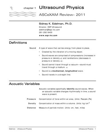
Ultrasound Physics ReviewArray (electronic): Imagine the inside of a digital watch, no moving parts, computerized orprogrammed. The goal is the same as the mechanical, to re off a sequence of scan linesacross the transducer face. But the crystals do not move. Instead there are multiple ofcrystals lined up in a row: 128-256 crystals. These crystals are electronically red or set offin a series individually or in groups across the face of the transducer in a sequentialmanner.Beam Former sets the order and timing of the sequenceNotice in the diagram to the left. The elements areorganized into sequential groups. Each group is onescan line/one beam. Together these elements in agroup form the aperture.Increase aperture increase beam sizeHuygens’ PrincipleBasically states that each wave produced by the elementswill combine or link together to form a wavefront. Thewavefront is a single beam of sound. This is what allows usto manipulate the beam shape electronically by focusingand/or steering.Electronic Focusing and SteeringIn addition to mechanical focus (lens), array transducers can also do electronic beamfocusing. Some arrays can also do electronic steering. Both work by using time delays.Since all the elements in a group will be linked together to become a wavefront, theyaffect each other. Just as a marching band can be guided in different shapes and directionsby timing the actions of the people, the shape and direction of the beam can bemanipulated by changing the timing or sequence of the elements. This is done by thebeam formerElectronic FocusingTime delays on the center elements shape of the beam becomes U shaped Beamconverges or get smaller as it travels. Adjustable focal positionFocal depth/position determines timing. Change position change timingMultiple focal zones: One pulse is needed for each focal point. Mult focal pointsmeans we will need multiple pulses(ie- 3 focal points 3 pulses per scan line)All array transducers can do dynamic / electronic / transmit focusing because theyall have a series of elements.fi14fiNot for Distribution
Ultrasound Physics ReviewElectronic Steering / PhasingSame principle as focusing except the time delays are now across the group ofelements to guide it in that direction phasing. The beam direction will gotowards the side the delay is on.Not all array transducers are capable of electronic steering.ONLY PHASED ARRAYSThe beam goes in the direction of the delay.Focusing : delay in center, beam focuses towards the centerSteering : delay on side, beam steered to the sideSlice thickness AKA elevational dimensionThickness of the beam.Beam is 3 dimensional. Like beam width, the narrower the better.Like a sharp knife, a thin slice thickness is able to “slice” through tissue clearly, especiallysmall echo free structures. When the elevational resolution is poor (thicker): unable toclearly display small cystic objects, blends surrounding echoes into structures.1 row of elements 1DTypical array transducers have one row of elements.One row mechanical focus xed (curved element, lens, or mirror)Unable to control elevational resolutionMulti rows 1.5D and 2DTransducers capable of 3D or 4D imaging, several rows of elements.Having multiple rows, dynamic elevation focusing is possible andbetter elevational resolution. 2D has more rows than 1.5D betterbeam control, thinner slice, and better eld of view. 2D can also do3D/4D imaging.fi15fiNot for Distribution
Ultrasound Physics ReviewLinear : High frequency 7MHzSmall parts, Vascular, MSKAka Linear sequential array. When scanning super cial structures thatrequire high resolution imaging but do not require penetration. Higherfrequencies provide improved axial resolution but reduced penetration. Linedensity is maintained in the far eld. Rectangular display Linear phased arrayLooks the same as linear probe. Capabilities of electronic beamsteering (phased). Gives option of wider FOV as a trapezoid display.Curvilinear : 2-6 MHzAbdomen, OB, Gyn, PelvisWhen exam requires larger FOV and penetration. Usually lowerfrequencies since large depth is normally required. Always choosethe highest possible frequency but with adequate penetration.Sector display (elements arranged in curve. Does NOT steer) Endocavity probes AKA tightly curved linear6-8 MHz (Transvaginal, Transrectal) Allows scanning closerto the area of interest, higher frequency transducer can beused, resulting in superior spatial resolution. Very low linedensity in far eld. Lateral resolution degrades with depth.Phased Array : 2.5-4 MHz EchoSmall footprint with wide FOV. Chosen for echo exams since views areobtained intercostally and heart is larger organ which requires wideFOV.Pie shaped display (sector). Obtains FOV by phasing (steering)Annular array: no longer used but here’s what you need to know:Concentric rings of elements (target sign) produces a symmetrical beam shape (cone orcylinder). Very poor elevational resolution. Electronic focusing but mechanical beamsteering. Sector FOVThink about which transducer and frequency you choose for each exam type.What? When? Why?Example: Why would you choose a low frequency curved for an abdomen exam on a large patient? Whywould you not choose a linear? How would you choose what frequency within the range?fi16fifiNot for Distribution
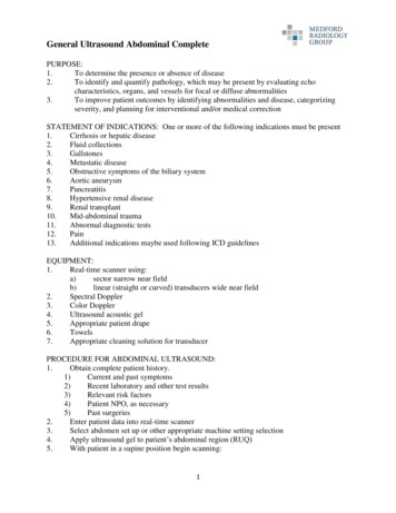
Ultrasound Physics ReviewImaging Principles and Instrumentation (28%)Pulse echo principle: When a sound wave encounters an interface of 2 differentimpedance levels, part of the pulse is re ected and the rest is transmitted. The machine isable to determine the distance of the re ector based on the time the echo takes to returnto the transducer. 1st use of pulse-echo principle was with SONAR (SOund NAvigationand Ranging) in WWI. 1st contact form of US- B scanner.A-mode (amplitude mode)- Displays re ections as height of the spikes. Strongre ections (signal amplitudes) would be plotted as a tall peak, low intensity assmaller peaks, and no echoes as a at line. Graph of received voltagesrepresenting the echoes and plots them according to their received time is plottedby oscilloscope.Time corresponds to distance distance measurements can be made.No longer used on modern machines.B-mode (brightness mode)- A-mode info converted into dots of varying brightnessand displayed on video screen. The higher the amplitude, the brighter the dot.Tall spike bright dot Small spike dark dot Flat areas echo-free. Usespulse echo principle, distance can be measured.Originally bi-stable (only black and white) now grey scale (shades of grey)M-mode (motion mode)- Detects the location of allstructures along a single scan line (line of sight) and displaysit according to time. If location changes with time MOTION. Displays stationary objects as well as movingobjects. The purpose is to see the motion of the movingtargets.Distance can also be measuredRange EquationAllows us to use the “time of ight” or round trip timeto calculate the distance travelled.Speed and time neededDistance RT time x prop speed213 microsecond ruleFor every 13µs of RT time re ector is 1cm deeperflflfl17flflflflNot for Distribution
Ultrasound Physics ReviewPulse Echo ProcessingPULSER controls the electric voltage that will be sent to transducer. Power and RatePowerAdjusting the Output Power will adjust the power of the voltages used. Increasing thestrength of the voltages will in turn increase the intensity of transmitted US pulse.Result to image increases overall intensity of the echoes (brighter image)To increase brightness of image do we always increase output power rst? Why not?RatePulser also controls the rate that pulses are sent. Adjusted when tech changes imagingdepth changes PRF. In order the change PRF, rate of voltages must also be changed.BEAM FORMER receives these pulses of voltage and programs order and timing ofsequence. Controls beam shape, focusing and direction of beam (by time delays)Anything that changes shape of beam or scan lines will be accomplished using the beamformer. Example: line density, sector angle, multiple focal zones, steering.TRANSDUCER converts voltage into pressure. Sound transmitted into body, echoproduced. Echo returns to transducer as a pressure wave. When hits crystal, pressure isconverted back into electric signal. Sent to machine for processing!What naturally occurs as sound travels through tissue? It attenuates. It loses energy. Whenthe echo is produced, that echo (which is still a sound wave) now has to travel through thesame tissue. Echo also attenuates. VERY WEAK!18fiNot for Distribution
Ultrasound Physics ReviewPRE-PROCESSINGRECEIVER receives the returning signals and knows that they have been weakened byattenuation and compensates by amplifying the received echoes.Compensation, ampli cation, gain all refer to this same processHow do we control?Overall gain- Increases overall brightness of ALL echoes(received signal amplitudes)TGC (time gain compensation)- attenuation worsens withdepth. TGC allows us to compensate for loss withincreasing depth RESULT: even brightness level acrossthe screenQ: How would your image appear if you had no TGC?A: Brighter at top with gradual darkening down the screen.Why? Because attenuation increases with depthRemember decibels? Let’s bring it full circle.Say your current gain setting is at 25 dB and you increase it to 28dB. What is the overall effect tothe intensity of the echoes? Doubles (3dB gain double intensity) pg 2When you make that change, what does increasing the gain actually do? Only increases receivedinfo nothing changes in the transmitted sound SAFE!The SIGNAL PROCESSOR is going to clean up thesignal and turn it into something machine can display.Like a processing plant, we start with raw material. Goalis to have a clean digital signal ready to be displayedRecti cation Turns
Ultrasound Physics Review Properties of the Medium Propagation speed Speed of sound in a medium. Totally dependent on medium only. Before we discuss how sound interacts with the tissue, we have to first understand the properties of our tissue. So forget about sound for a moment. Propagation speed is a property of the medium.