Transcription
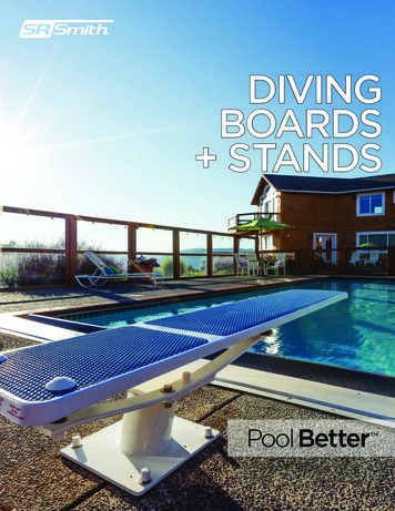
TECBOR BOARDSTECBOR A & B BOARDS: METAL STRUCTURE: COLUMNS AND BEAMS CABLE TRAY VENTILATION DUCTS: HORIZONTAL AND VERTICAL NON-STRUCTURAL ELEMENTS. WALLS SUSPENDED CEILINGS AND SLABS PROTECTION CURTAIN WALLS TUNNELS2
TABLE OF CONTENTSINTRODUCTION3TECBOR PRESENTATION4TECHNICAL CHARACTERISTICS AND SPECIFICATIONS5SOLUTIONS61 – Metal Structure62 – Cable Tray103 – Ventilation Ducts124 – Non-structural Elements. Walls265 – Suspended Ceilings and Slabs Protection386 – Curtain Walls447 – Tunnels48REFERENCE WORKS56 TECBOR BOARDS CATALOGUEFire protectionThermal insulationAcoustic absorptionFire protectionin industrial plantsReference works
2
INTRODUCTIONMercor is the largest manufacturer and supplier of comprehensive passive fireprotection systems in Poland. Together with its subsidiaries: Spanish Tecresa,Hasil in the Czech Republic, and the Polish company BEM, represents a capitalgroup being one of the largest sector entities in Europe.At present, products labelled as Mercor, like fire doors and partitions, naturalsmoke and heat exhaust systems, fire ventilation systems and fire protectionsystems for building structures, set the standard for many domestic and foreignbuilding projects.Mercor Group continually enhances its product range, offering its customersthe most innovative solutions available on the market. The products are certifiedaccording to European standards and tested in accredited laboratories.The catalogue we have made has been fashioned to present all interested partieswith the Tecbor fireproof boards. They are manufactured by the Spanish companyTecresa Protección Pasiva, which joined the Mercor Group in February 2008.Tecresa Proteccion Pasiva s.l. as an owner of fire protection plate systemtechnologies for building structures has made a great deal of effort in order todesign new fire protection solutions. All of the Tecbor boards manufactured byTecresa are backed by several tests performed in certified laboratories accordingto EN and ASTM standards, as well as internal protocols such as RWS for tunnels,HCM heating curves, etc. They bear the CE Mark which requires the strictestquality controls in order to offer its customers fully warranted products.Tecbor has achieved an outstanding reputation on the Spanish market over thelast six years. In 2009, Mercor begun marketing Tecbor across a wide range ofinternational markets including the UK, South East Europe, Poland, the MiddleEast and selected markets in Asia and currently successfully extends its activityin new ones.Customer response has been extremely positive and already several projects havebeen signed up including the highly prestigious Al Salam Street tunnel in AbuDhabi and the new Olympic Village in London. Already the Tecbor brand nameis achieving a high level of awareness and a reputation for quality, value, andperformance on a global scale.3
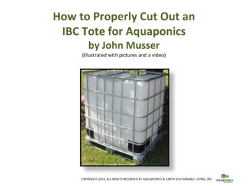
TECBOR – GENERAL CHARACTERISTICSCOMPOSITIONTecbor A and B boards are rigid fire protection panels made ofmagnesium oxide, silicates, and other additives, finished with afibreglass mesh on both sides.TESTSTecbor A and B boards are tested in official laboratories certifiedby ENAC or other similar international entities and pursuantto EN and ASTM standards, among others. Given our concernto make Tecbor an integral solution, we conduct real-scale testsin tunnels, hydrocarbon curve tests, RWS curve tests or testsunder the American UL standard.10 mm12 mmTecbor A and B is classified as A1 (non combustible) pursuant toEuropean Standard EN 13501-1.TRACEABILITYTecbor AFIRE REACTION15 mmQUALITYTecbor A and B boards bear the CE Mark (ETA 09/0057) pursuantto the specifications of the ETAG 018-4 Guide approved by EOTA.Tecbor BAll of our products undergo internal quality control procedures toguarantee the history, location and path of our batches.20 mmCommitment to and effort in the creation of a market leadingproduct, certified by BSI pursuant to standard ISO 9001.HEALTH AND SAFETYTecbor A and B boards do not contain hazardous substances,according to the Commission’s Database DS041/051.30 mmTECHNICAL ASSISTANCEWe provide customised assistance on both building solutionsand building regulations.APPLICATIONWe seek to make our products easy and quick to assemble, thusdelivering the most competitive solutions in the market.440 mm
TECHNICAL CHARACTERISTICS AND SPECIFICATIONSSPECIFICATIONSTECBOR ATECBOR BNORMATIVEMagnesium oxide, silicates& other additivesMagnesite based, silicate& other additives–Fire PerformanceNon-combustible Euroclass A1Non-combustible Euroclass A1EN 13501-1:2002Dry Density (40ºC)700 kg/m 10%650 kg/m 10%EN 12467Density (23ºC and 50% HR)730 kg/m 10%680 kg/m 10%EN 124670.27 W/mk0.19 W/mkEN 126648 - 108 - 10EN 13468CompositionThermal ConductivityAlkalinity pHWater absorption capacity331.9 kg/m2334.12 kg/m2EN 16093.9 x 10 (Kg/m sPa)3 x 10 (Kg/m sPa)EN ISO 12572Lengthwise tolerance 5 mm 5 mmEN 12467Widthwise tolerance 3 mm 3 mmEN 124673.6 (1/ C)* 10E-53.1 (1/ C)* 10E-5EN ISO 10.545-8/97Thickness margin 1 mm 2 mm / -1 mmEN 12467Edge straightnessLevel l – 0.1%Level l - 0,1%EN 124674.55%3.30%103 204/93Resistance to water erosionRL 0.75RL 0.75EN 12467Modulus of elasticity (MPa)3018.72149.2EN 12089; EN 310Flexural strength MOR (MPa)7.23.58EN- 12467Tensile strength perpendicularto fibre (MPa)1.20.68EN - 1607Tensile strength paralellto fibre (MPa)1.590.81EN 1608Comprenssive strength (MPa)7.074.64EN - 826Dimensional stability 0.25% 0.25%EN 326-1Microbial proliferationNoNoEN 1340325 years Z2 (indoor use)25 years Z2 (indoor use)ETA 09/0057Steam permeabilityThermal expansion (20-100 C)Organic matter contentLife-92-92SOME VALUES QUOTED RELATE TO INTERNAL TESTING ACROSS THE SIZE RANGE. INDIVIDUAL TEST CERTIFICATESARE AVAILABLE UPON REQUEST.WE RESERVE THE RIGHT TO IMPROVE PRODUCT PERFORMANCE AT ANY TIME AND WITHOUT PRIOR REFERENCE .STRICTER BOARD TOLERANCES CAN BE ACHIEVED TO SUIT SPECIFIC PROJECT REQUIREMENTS.ALL DATA AND TECHNICAL PARAMETERS GIVEN IN HEREWITH CATALOGUE WERE ESTIMATED AND PROVIDED ACCORDINGTO THE BEST TECHNICAL KNOWLEDGE AND AVAILABLE INTERNAL TESTS AND EXPERTISE.DATA IN DETAILS WILL BE ACCOMPANIED BY RELEVANT TECHNICAL TESTS UPON REQUEST, WHICH TESTS WILL BE CARRIED OUTIN LABORATORIES AND RESEARCH ESTABLISHMENTS ENTITLED TO PROCEED SUCH.5
1 – Metal Structure6Steel structures are used for building purposes worldwide.One of the main advantages is that they have great resistanceper weight unit, which provides them with huge versatility andthe possibility of creating complex yet light structures.Several tests with Tecbor have been performed pursuantto standard EN 13381-4 to determine the board’s fire protectionproperties when applied to steel structural elements suchas beams, columns or tension elements.However, the thermal conductivity of steel representsa disadvantage. Therefore, in the event of a fire, the gradualincrease in temperature plus steel high heat transmissionresult in a substantial reduction of the structure’s bearingcapacity and mechanical resistance. The resistance andelastic limit are modified above 250 C, and above roughly500 C the drop in resistance is significant enough not tosupport its design capacity.Tecbor has been tested to cover a great variety of steel profilescharacterised by their section factors. Likewise, it has beentested for several standard specified design temperatures.
TECBOR A & B ENCLOSED SECTION FACTOR (A/V)The necessary board thickness for the steel structure protection depends on the A/V ratioof the steel section.The A/V rate is a measure of the speed at which a steel section is heated during a fire.The higher section factor is the thicker the board will be for the profile fire protection.A/V (m-1)where A heated perimeter in meters (m)where V total crossed sectional area in sqm (m2)The information in this chart appears in the test report under file 10/1483-1014.Valid chart for 500 C design temperature on steel pursuant to ENV 13381-4.Section Factor (A/V)THICKNESS (mm)mˉ¹30 min60 min90 min120 min180 min240 �–265[19][19][24][31]––VALUES WITHOUT BRACKETS ARE VALUES OBTAINED DIRECTLY FROM TESTING.VALUES IN BRACKETS COME FROM EXTRAPOLATION PERFORMED BY THE LABORATORY ACCORDING TO THE NORMATIVE.7
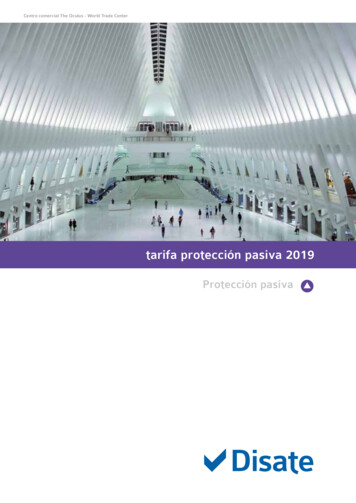
1.1 – METAL STRUCTURE PROTECTION. COLUMNSTESTSStandard: ENV 13381-4Laboratory: APPLUSTest No: 10/1483-1014467SOLUTION1 Tecbor boards.2 Tecbor B 40 mm boards.3 Self-tapping screw (size according to board).34 Steel column.5 Tecbor joint paste.6 30x30x0.6 mm angle section.7 45x15x0.6 mm omega.8 5x80 mm self-tapping screw.DESCRIPTION OF ASSEMBLYFix 45x15x0.6 mm omega profiles to the outer side of the metalprofile’s flange to be protected with steel nails every 725 mm.5Fix 30x30x0.6 mm angle section to the Tecbor board strips, andthen the strips onto the omega profiles with self-tapping screwsevery 250 mm. Assemble the strips.Use Tecbor joint paste in screw heads and between boards.NOTE: If protection procedure is done with 40 mm Tecbor B boards,they may be joined without auxiliaries using 5x80 mmscrews every 250 mm.1346452185PLAN87PLAN 40 mm board assembly plan
1.2 – METAL STRUCTURE PROTECTION. BEAMS732615TESTSStandard: ENV 13381-4Laboratory: APPLUSTest No: 10/1483-1014SOLUTION1 Tecbor boards.2 Self-tapping screw (size according to board).3 Steel beam.4 Tecbor joint paste.5 30x30x0.6 mm angle section.6 45x15x0.6 mm omega.7 Slab.8 6x60 mm metal plug.783DESCRIPTION OF ASSEMBLY2Fix 45x15x0.6 mm omega profiles to the outer side of the metalprofile’s flange to be protected with steel nails every 725 mm. Fixthe 30x30x0.6 mm angle to the slabs with 6x60 mm plugs every300 mm.15Fix 30x30x0.6 mm lower angle section to the Tecbor board stripsand these onto the omega profiles and onto the angle anchored tothe slabs with self-tapping screws every 250 mm.Use Tecbor joint paste in screw heads and between boards.4PLAN69
2 – Cable TrayProtecting the wiring adequately will be crucial when electricalsupply systems must be kept in optimal running conditionsduring fires. In tunnels, heavy traffic buildings or high-rises,it is of paramount importance to perform orderly evacuationswhile basic systems keep running.Tecbor B 40 mm boards have been tested pursuant togeneral requirements in standard EN 1363-1 by covering acable tray from different sections. Then, other tests have beenrun on electrical conductivity, short-circuits in cables andgrounding.10Facilities may be accessed through inspection hatches.Likewise, Tecsel Grids allowing for ventilation and sealingthe hole in case of fire have been tested (For additionalinformation, please contact our Sales Department.).
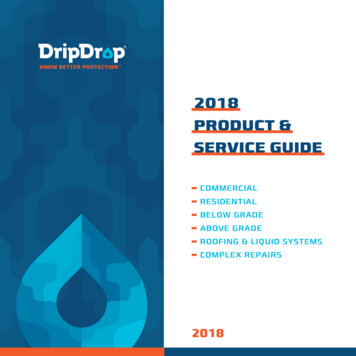
2.1 TECBOR B 40 – EI-120 CABLE PROTECTION317854TESTS62Standard: ENV 1363-1. UL 1709 Heating CurveLaboratory: CIDEMCOTest No: 2541710SOLUTION1 Tecbor B 40 mm boards.2 Tecbor B 20 mm boards.3 M12 rod.4 Tecbor joint paste ready to use.95 50x50x5 mm angle section every 1000 mm.36 3.5x45 mm self-drilling screw.7 5.2x80 mm self-tapping screw.8 3.5x45 mm self-tapping screw.29 Slab.110 Cable tray.5CROSS VIEWDESCRIPTION OF ASSEMBLY378106The duct is anchored to the slabs with a 12 mm rod and supportedby 50x50x5 mm angle sections.4Board joints and screw heads should be covered with Tecbor joint paste ready to use.215The tray is protected by a layer of Tecbor B 40 mm boards settogether with 5.2x80 mm self-tapping screws. At duct sectionjoints, place a 200 mm wide board strip of 20 mm Tecbor Band fix it to the metal tray and to each other using 3.5x45 mmscrews.Penetrations seals:DETAILED VIEWFill the hole between the duct and the structural work with 50 mmand 145 kg/m3 rock wool and paint both sides with Tecbor jointpaste ready to use.11
3 – Ventilation DuctsMost of new constructions are crossed by several servicessuch as cables, piping, ducts, ventilation ducts, etc. Thisuninterrupted design alters the subdivisions of the splittingelements, allowing fire and smoke to pass through differentfire areas.For ventilation ducts there are several solutions to preventsmoke and fire propagation throughout the installations.Our solution consists in providing elements with a resistanceequal to or above the resistance of crossed elements.12
3.1 TECBOR B 20 20 TYPE A – EI-120 HORIZONTAL DUCT725116314TESTSStandard: EN 1366-1Laboratory: CIDEMCOTest No: 18037-1-2/M1SOLUTION1 Tecbor B 20 mm boards.2 M16 threaded rod.3 40x40x2 mm angle section.4 3.5 x 45 mm self-drilling screw.5 Tecbor joint paste ready to use.8116 50x50x5 mm L-shaped support.7 Tecbor B 20 mm plate to cover joints.8 10x100 mm metal plug.9 Masonry.10 50 mm and 145 kg/m3 density rock wool.111 3.5x45 mm self-tapping screw.107A-A SECTION9DESCRIPTION OF ASSEMBLYThe duct comprises 2 Tecbor B 20 mm boards. Lower layerboards are fastened through 3.5x45 mm self-tapping screwsevery 300 mm. Once built, the duct inner part is reinforced with40x40x2 mm steel angle sections. The second layer of the boardis fastened with 3.5x45 mm self-drilling screws directly onto theangle sections. Duct sections are connected covering the jointwith 250-300 mm wide Tecbor B 20 mm plates fastened to theduct with 3.5x45 mm self-tapping screws every 250 mm.Joints between boards, other joints and screw heads should besealed with Tecbor joint paste ready to use.Crossing fire sectors:VERTICAL VIEWThe space between the duct and the structural work is filled withrock wool 145 kg/m³ density. Then, 250 mm wide Tecbor B 20 mmboard strips are placed around the duct and anchored to thestructural work with 10x100 mm plugs on both sides. Afterwards,a ring surrounding the duct is made with 250 mm strips fastenedwith 3.5x45 mm self-tapping screws.13
3.2 TECBOR B 40 TYPE A – EI-120 HORIZONTAL DUCT42751TESTSStandard: EN 1366-13Laboratory: APPLUSTest No: 10/101165-131SOLUTION1 Tecbor B 40 mm boards.2 M16 threaded rod.3 50x50x5 mm L-shaped support.4 Tecbor B 40 mm plate to cover joints.5 5x80 mm self-tapping screw.76 Masonry.7 Tecbor joint paste ready to use.5DESCRIPTION OF ASSEMBLYBoards are fastened with 5x80 mm self-tapping screws every 250 mm.Duct sections are connected covering the joint with 250-300 mmwide Tecbor B 40 mm plates fastened to the duct with 5x80 mmself-tapping screws every 250 mm.SCREW DETAILS2641The duct is supported by 50x50x5 mm horizontal angle sectionsand hung from the slabs with M16 rod, nut and bolt. Distancebetween hanging elements is 1 m. Joints between boards, otherjoints and screw heads should be sealed with Tecbor joint pasteready to use.Crossing fire sectors:PLAN14The space between the duct and the structural work is filled withrock wool 145 kg/m³ density. Then, 250 mm wide Tecbor B 40 mmboard strips are placed around the duct and anchored to thestructural work with 10x100 mm plugs on both sides. Afterwards,a ring surrounding the duct is made with 250 mm strips fastenedwith 5x80 mm self-tapping screws.
3.3 TECBOR B 20 20 TYPE B – EI-120 HORIZONTAL DUCT725631SOLUTIONTESTSStandard: EN 1366-11 Tecbor B 20 mm boards.Laboratory: AFITI LICOF2 M16 threaded rod.Test No: 7169/063 40x40x2 mm angle section.4 3.5x45 mm self-tapping screw.5 Tecbor joint paste ready to use.6 50x50x5 mm L-shaped support.7 Tecbor B 20 mm plate to cover joints.8 M16 nut and bolt.9 3.5x45 mm self-drilling screw.94DESCRIPTION OF ASSEMBLYThe duct comprises 2 Tecbor B 20 mm boards. Lower layerboards are fastened through 3.5x45 mm self-tapping screwsevery 300 mm. Once built, the duct inner part is reinforced with40x40x2 mm steel angle sections. The second layer of the boardsis fastened with 3.5x45 mm self-drilling screws directly onto theangle sections. Duct sections are connected covering the jointwith 250-300 mm wide Tecbor B 20 mm plates fastened to theduct with 3.5x45 mm self-tapping screws every 250 mm.35SCREW DETAILSThe duct is supported by 50x50x5 mm horizontal angle sectionsand hung from the forging by means of M16 rod, ring and bolt.Distance between hanging elements is 1 m. Joints betweenboards, other joints and screw heads should be sealed withTecbor joint paste ready to use.12Crossing fire sectors:386PLANThe space between the duct and the structural work is filled withrock wool 145 kg/m³ density. Then, 250 mm wide Tecbor B 20 mmboard strips are placed around the duct and anchored to thestructural work with 10x100 mm plugs on both sides. Afterwards,a ring surrounding the duct is made with 250 mm strips fastenedwith 3.5x45 mm self-tapping screws.15
3.4 TECBOR 40 TYPE B – EI-120 HORIZONTAL DUCT479521TESTSStandard: EN 1366-1Laboratory: CIDEMCOTest No: 19078-1/-2 M1SOLUTION1 Tecbor B 40 mm boards.2 50x50x5 mm L-shaped support.3 50 mm and 145 kg/m3 density rock wool.4 Tecbor B 40 mm plate to cover joints.5 5x80 mm self-tapping screw.86 Masonry.57 M16 rod.8 10x100 mm metal plug.9 Tecbor joint paste ready to use.13DESCRIPTION OF ASSEMBLY4Boards are fastened with 5x80 mm self-tapping screws every 250 mm.Duct sections are connected covering the joint with 250-300 mmwide Tecbor B 40 mm plates fastened to the duct with 5x80 mmself-tapping screws every 250 mm.67641The duct is supported by 50x50x5 mm horizontal angle sectionsand hung from the slabs with M16 rod, nut and bolt. Distancebetween hanging elements is 1.00 m. Joints between boards,other joints and screw heads should be sealed with Tecbor jointpaste ready to use.Crossing fire sectors:PLAN16The space between the duct and the structural work is filled withrock wool 145 kg/m³ density. Then, 250 mm wide Tecbor B 40 mmboard strips are placed around the duct and anchored to thestructural work with 10x100 mm plugs on both sides. Afterwards,a ring surrounding the duct is made with 250 mm strips fastenedwith 5x80 mm self-tapping screws.
3.5 TECBOR B 20 20 TYPE A – EI-120 VERTICAL DUCTTESTSStandard: EN 1366-18Laboratory: CIDEMCO6Test No: 19052-2/-315472109SOLUTION1 Tecbor B 20 mm boards.2 3.5x15 mm self-tapping screw.3 3.5x45 mm self-tapping screw.4 40x40x0.6 mm angle section.5 3.5x45 mm self-drilling screw.6 40x40x2 mm angle section.7 Tecbor B 20 mm plate to cover joints.8 Tecbor joint paste ready to use.9 10x100 mm metal plug.10 Masonry.365DESCRIPTION OF ASSEMBLY1The duct comprises 2 Tecbor B 20 mm boards. Lower layerboards are fastened through 3.5 x 45 mm self-tapping screwsevery 300 mm. Once built, the duct inner part is reinforced with40x40x2 mm steel angle sections. The second layer of the boardsis fastened with 3.5x45 mm self-drilling screws directly onto theangle sections.DETAILED VIEW101Crossing fire sectors:97PLANDuct sections are connected covering the joint with 250-300 mmwide Tecbor B 20 mm plates fastened to the duct with 3.5x45 mmself-tapping screws every 250 mm. Joints between boards, otherjoints and screw heads should be sealed with Tecbor joint pasteready to use.The space between the duct and the structural work is filled with145 kg/m³ rock wool. Then, 250 mm wide Tecbor B 20 mm boardstrips are placed around the duct and anchored to the structuralwork with 10x100 mm plugs on both sides. Afterwards, a ringsurrounding the duct is made with 250 mm strips fastened with3.5x45 mm self-tapping screws.17
3.6 TECBOR B 40 TYPE A – EI-120 VERTICAL DUCT73164298TESTSStandard: EN 1366-1Laboratory: CIDEMCOTest No: 19318-2/-3 M1SOLUTION1 Tecbor B 40 mm boards.2 3.5x15 mm self-tapping screw.3 5x80 mm self-tapping screw.4 40x40x0.6 mm angle section.5 50 mm and 145 kg/m3 density rock wool.96 Tecbor B 40 mm plate to cover joints.67 Tecbor joint paste ready to use.88 10x100 mm metal plug.9 Masonry.DESCRIPTION OF ASSEMBLYPLAN891365Boards are fastened with 5x80 mm self-tapping screws every 250 mm.Duct sections are connected covering the joint with 250-300 mmwide Tecbor B 40 mm plates fastened to the duct with 5x80 mmself-tapping screws every 250 mm. Joints between boards, otherjoints and screw heads should be sealed with Tecbor joint pasteready to use.Crossing fire sectors:A-A SECTION18The space between the duct and the structural work is filled withrock wool 145 kg/m³ density. Then, 250 mm wide Tecbor B 40 mmboard strips are placed around the duct and anchored to thestructural work with 10x100 mm plugs on both sides. Afterwards,a ring surrounding the duct is made with 250 mm strips fastenedwith 5x80 mm self-tapping screws.
3.7 TECBOR B 20 20 TYPE B – EI-120 VERTICAL DUCTTESTS8Standard: EN 1366-16Laboratory: CIDEMCO1547Test No: 19052-1/-32109SOLUTION1 Tecbor B 20 mm boards.2 3.5x15 mm self-tapping screw.3 3.5x45 mm self-tapping screw.4 40x40x0.6 mm angle section.5 3.5x45 mm self-drilling screw.6 40x40x2 mm angle section.7 Tecbor B 20 mm plate to cover joints.8 Tecbor joint paste ready to use.9 10x100 mm metal plug.10 Masonry.11 50 mm and 145 kg/m3 density rock wool.74917DESCRIPTION OF ASSEMBLY310211Duct sections are bonded covering the joint with 250-300 mmwide Tecbor B 20 mm plates fastened to the duct with 3.5x45 mmself-tapping screws every 250 mm. Joints between boards, otherjoints and screw heads should be sealed with Tecbor joint pasteready to use.SECTION3615PLAN DETAILThe duct comprises 2 Tecbor B 20 mm boards. Lower layerboards are fastened through 3.5 x 45 mm self-tapping screwsevery 300 mm. Once built, the duct inner part is reinforced with40x40x2 mm steel angle sections. The second layer of the boardsis fastened with 3.5x45 mm self-drilling screws directly onto theangle sections.Crossing fire sectors:The space between the duct and the structural work is filled withrock wool 145 kg/m³ density. Then, 250 mm wide Tecbor B 20 mmboard strips are placed around the duct and anchored to thestructural work with 10x100 mm plugs on both sides. Afterwards,a ring surrounding the duct is made with 250 mm strips fastenedwith 3.5x45 mm self-tapping screws.19
3.8 TECBOR B 40 TYPE B – EI-120 VERTICAL DUCT231645TESTSStandard: EN 1366-1Laboratory: CIDEMCOTest No: 19318-1-3/M1SOLUTION1 Tecbor B 40 mm boards.2 5x80 mm self-tapping screw.3 Tecbor joint paste ready to use.4 10x100 mm metal plug.55 Masonry.614DESCRIPTION OF ASSEMBLYBoards are fastened with 5x80 mm self-tapping screws every 250 mm.Duct sections are connected covering the joint with 250-300 mmwide Tecbor B 40 mm plates fastened to the duct with 5x80 mmself-tapping screws every 250 mm. Joints between boards, otherjoints and screw heads should be sealed with Tecbor joint pasteready to use.PLANCrossing fire sectors:21DETAILED VIEW206 Tecbor B 40 mm plate to cover joints.The space between the duct and the structural work is filled withrock wool 145 kg/m³ density. Then, 250 mm wide Tecbor B 40 mmboard strips are placed around the duct and anchored to thestructural work with 10x100 mm plugs on both sides. Afterwards,a ring surrounding the duct is made with 250 mm strips fastenedwith 5x80 mm self-tapping screws.
3.9 TECBOR 40 10 TYPE A – EI-180 HORIZONTAL DUCT71154812TESTSSOLUTIONStandard: EN 1366-11 Tecbor B 40 mm boards.Laboratory: CIDEMCO2 Tecbor A 10 mm boards.Test No: 205293 5x80 mm self-tapping screw.4 3.9x35 mm self-tapping screw.5 50x50x5 mm angle section.6 50 mm and 145 kg/m3 density rock wool.7 Tecbor B 40 mm plate to cover joints.118 Tecbor joint paste ready to use.109 10x100 mm metal plug.67210 Masonry.11 M16 rod.DESCRIPTION OF ASSEMBLYThe duct comprises one Tecbor B 40 mm layer and one Tecbor A 10 mm layer. First layer boards are fastened with 5x80 mm selftapping screws. The 10 mm board is fixed to the first layer with3.9x35 mm screws. Duct sections are bonded covering the jointwith 250-300 mm wide Tecbor B 40 mm plates fastened to theduct with 5x80 mm self-tapping screws every 250 mm.PLAN2The duct is supported by 50x50x5 mm horizontal angle sectionsand hung from the slabs with M16 rod, nut and bolt. Distancebetween hanging elements is 1 m.73Joints between boards, other joints and screw heads should besealed with Tecbor joint paste ready to use.9Crossing fire sectors:10The space between the duct and the structural work is filled withrock wool 145 kg/m³ density. Then, 250 mm wide Tecbor B 40 mmboard strips are placed around the duct and anchored to thestructural work with 10x100 mm plugs on both sides. Afterwards,a ring surrounding the duct is made with 250 mm strips fastenedwith 5x80 mm self-tapping screws.1VERTICAL VIEW21
3.10 TECBOR 40 10 TYPE B – EI-180 HORIZONTAL DUCT7954812SOLUTIONTESTSStandard: EN 1366-11 Tecbor B 40 mm boards.Laboratory: CIDEMCO2 Tecbor A 10 mm boards.Test No: 199673 5x80 mm self-tapping screw.4 3.9x35 mm self-tapping screw.5 50x50x5 mm angle section.6 50 mm and 145 kg/m3 density rock wool.7 Tecbor B 40 mm plate to cover joints.8 Tecbor joint paste ready to use.39 M16 rod and nut.DESCRIPTION OF ASSEMBLY8142SCREW DETAILS1The duct is supported by 50x50x5 mm horizontal angle sectionsand hung from the slabs by means of M16 rod, washer and bolt.Distance between hanging elements is 1 m.Joints between boards, other joints and screw heads should besealed with Tecbor joint paste ready to use.2Crossing fire sectors:95DUCTS FASTENING DETAIL22The duct comprises one Tecbor B 40 mm layer and one Tecbor A 10 mm layer. First layer boards are fastened with 5x80 mm selftapping screws. The 10 mm board is fixed to the first layer with3.9x35 mm screws. Duct sections are connected covering the jointwith 250-300 mm wide Tecbor B 40 mm plates fastened to theduct with 5x80 mm self-tapping screws every 250 mm.The space between the duct and the structural work is filled withrock wool 145 kg/m³ density. Then, 250 mm wide Tecbor B 40 mmboard strips are placed around the duct and anchored to thestructural work with 10x100 mm plugs on both sides. Afterwards,a ring surrounding the duct is made with 250 mm strips fastenedwith 5x80 mm self-tapping screws.
3.11 TECBOR 40 10 TYPE A – EI-180 VERTICAL DUCT8321457109TESTSStandard: EN 1366-1Laboratory: CIDEMCOTest No: 19966 M1SOLUTION1 Tecbor B 40 mm boards.2 Tecbor A 10 mm boards.3 5x80 mm self-tapping screw.4 3.9x35 mm self-tapping screw.5 40x40x0.6 mm angle section.6 50 mm and 145 kg/m3 density rock wool.7 Tecbor B 40 mm plate to cover joints.8 Tecbor joint paste ready to use.9 10x100 mm metal plug.1010 Masonry.71DESCRIPTION OF ASSEMBLY9The duct comprises one Tecbor B 40 mm layer and one Tecbor A 10 mm layer. First layer boards are fastened with 5x80 mm selftapping screws. The 10 mm board is fixed to the first layer with3.9x35 mm screws.2PLAN91275106A-A SECTIONDuct sections are connected covering the joint with 250-300 mmwide Tecbor B 40 mm plates fastened to the duct with 5x80 mmself-tapping screws every 250 mm. Joints between boards, otherjoints and screw heads should be sealed with Tecbor joint pasteready to use.Crossing fire sectors:The space between the duct and the structural work is filled withrock wool 145 kg/m³ density. Then, 250 mm wide Tecbor B 40 mmboard strips are placed around the duct and anchored to thestructural work with 10x100 mm plugs on both sides. Afterwards,a ring surrounding the duct is made with 250 mm strips fastenedwith 5x80 mm self-tapping screws.23
3.12 TECBOR 40 10 TYPE B – EI-180 VERTICAL DUCT8321475109TESTSStandard: EN 1366-1Laboratory: CIDEMCOTest No: 20330 M1SOLUTION1 Tecbor B 40 mm boards.2 Tecbor A 10 mm boards.3 5x80 mm self-tapping screw.4 3.9x35 mm self-tapping screw.5 40x40x0.6 mm angle section.6 50 mm and 145 kg/m3 density rock wool.7 Tecbor B 40 mm plate to cover joints.8 Tecbor joint paste ready to use.9 10x100 mm metal plug.1010 Masonry.71DESCRIPTION OF ASSEMBLY9The duct comprises one Tecbor B 40 mm layer and one Tecbor A 10 mm layer. First layer boards are fastened with 5x80 mm selftapping screws. The 10 mm board is fixed to the first layer with3.9x35 mm screws.2PLAN912710A-A SECTION246Duct sections are connected covering the joint with 250-300 mmwide Tecbor B 40 mm plates fastened to the duct with 5x80 mmself-tapping screws every 250 mm. Joints between boards, otherjoints and screw heads should be sealed with Tecbor joint pasteready to use.Crossing fire sectors:The space between the duct and the structural work is filled withrock wool 145 kg/m³ density. Then, 250 mm wide Tecbor B 40 mmboard strips are placed around the duct and anchored to thestructural work with 10x100 mm plugs on both sides. Afterwards,a ring surrounding the duct is made with 250 mm strips fastenedwith 5x80 mm self-tapping screws.
BUILDING SOLUTIONS FOR DUCTS*1. 3-sided horizontal duct.2. 2-sided horizontal duct.3. Section changes.4. Dislevelment.5. Elbow-shaped elements.6. Branches.7. Vertical anchor and horizontal coupling.8. 3-sided vertical duct.9. 2-sided vertical duct.* For building details on connections, please contact the Sales Department.25
4 – Non-structural Elements – WallsNon-structural walls, which separate fire areas, should befire resistant as stipulated in standard EN 1364-1.When in fire resistance tests for non-structural elements oneedge is left free (Part 1: Walls), the standard allows increasingthe width. With regard to increasing the height, the standardis clear and precise. When the test is run at least at 3 metreshigh, it may be increased up to 4 metres.26Very often, internal partitions are higher than 4 metres.We have been the first to develop large partitions and offersthe most efficient and convenient solution for this type ofworks. Besides, penetrations produced between differentfire sectors must be sealed off; for example, in the case ofcrossing installations.
4.1 TECBOR A 12 – EI-120 PARTITION25371413645TESTSStandard: EN 1364-1Laboratory: CIDEMCOTest No: 17826-1/-
Tecresa Protección Pasiva, which joined the Mercor Group in February 2008. Tecresa Proteccion Pasiva s.l. as an owner of fire protection plate system technologies for building structures has made a great deal of effort in order to design new fire protection solutions. All of the Tecbor boards manufactured by