Transcription
OPENLight: Science & Applications (2016) 5, e16060; doi:10.1038/lsa.2016.60& 2016 CIOMP. All rights reserved 2047-7538/16www.nature.com/lsaORIGINAL ARTICLEPixel super-resolution using wavelength scanningWei Luo1,2,3, Yibo Zhang1,2,3, Alborz Feizi1,2,3, Zoltán Gö rö cs1,2,3 and Aydogan Ozcan1,2,3,4Undersampling and pixelation affect a number of imaging systems, limiting the resolution of the acquired images, whichbecomes particularly significant for wide-field microscopy applications. Various super-resolution techniques have been implemented to mitigate this resolution loss by utilizing sub-pixel displacements in the imaging system, achieved, for example, byshifting the illumination source, the sensor array and/or the sample, followed by digital synthesis of a smaller effective pixel bymerging these sub-pixel-shifted low-resolution images. Herein, we introduce a new pixel super-resolution method that is basedon wavelength scanning and demonstrate that as an alternative to physical shifting/displacements, wavelength diversity can beused to boost the resolution of a wide-field imaging system and significantly increase its space-bandwidth product. We confirmedthe effectiveness of this new technique by improving the resolution of lens-free as well as lens-based microscopy systems anddeveloped an iterative algorithm to generate high-resolution reconstructions of a specimen using undersampled diffraction patterns recorded at a few wavelengths covering a narrow spectrum (10–30 nm). When combined with a synthetic-aperture-baseddiffraction imaging technique, this wavelength-scanning super-resolution approach can achieve a half-pitch resolution of250 nm, corresponding to a numerical aperture of 1.0, across a large field of view (420 mm2). We also demonstrated theeffectiveness of this approach by imaging various biological samples, including blood and Papanicolaou smears. Compared withdisplacement-based super-resolution techniques, wavelength scanning brings uniform resolution improvement in all directionsacross a sensor array and requires significantly fewer measurements. This technique would broadly benefit wide-field imagingapplications that demand larger space-bandwidth products.Light: Science & Applications (2016) 5, e16060; doi:10.1038/lsa.2016.60; published online 8 April 2016Keywords: holographic imaging; on-chip microscopy; pixel super-resolution; wavelength scanning; wide-field imagingINTRODUCTIONHigh-resolution imaging across a wide field of view (FOV) is essentialfor various applications in different fields and requires imagingsystems to have large space-bandwidth products. Ever since thewidespread adoption of CCDs (charge-coupled devices) and complementary metal-oxide semiconductor (CMOS)-based image sensors tocapture digital images, a tremendous amount of research anddevelopment effort has been devoted to optics, semiconductortechnologies and signal processing to create high-resolution andwide-field imaging and microscopy systems. In conventional lensbased optical imaging designs, a large space-bandwidth product can beachieved by using higher magnification and larger lenses, and theimage sensors are accordingly made larger in area with higher pixelcounts. Another approach is to make image sensors with a smallerpixel pitch while still maintaining a relatively large active area.However, both of these approaches have drawbacks: Larger opticalcomponents make the imaging system bulky and significantly moreexpensive; in contrast, physically reducing the pixel size sacrificesthe signal-to-noise ratio because a smaller light sensing area is made1available for each pixel, reducing the external quantum efficiency ofthe imager chip1.As an alternative, the optical signal processing community hasprovided a powerful framework, termed pixel super-resolution2–6, toobtain a high-resolution image from a series of low-resolution (that is,undersampled) images. Pixel super-resolution was originally developedin lens-based, point-to-point projection imaging systems2–6 and waslater applied to lens-free and holographic imaging techniques7–12 tosignificantly enhance the space-bandwidth product of the reconstructed images using both CCD and CMOS imager chips. In eitherimplementation, lens-based or lens-free, this super-resolution framework requires low-resolution undersampled measurements to havesub-pixel shifts with respect to each other so that new andindependent information can be exploited at each raw measurement(even though pixelated) to digitally synthesize a much smaller effectivepixel size for the reconstructed image.Herein, we introduce a fundamentally new pixel super-resolutionmethod that utilizes wavelength scanning to significantly improve theresolution of an undersampled or pixelated imaging system, withoutElectrical Engineering Department, University of California, Los Angeles, CA 90095, USA; 2Bioengineering Department, University of California, Los Angeles, CA 90095, USA;California NanoSystems Institute (CNSI), University of California, Los Angeles, CA 90095, USA and 4Department of Surgery, David Geffen School of Medicine, University ofCalifornia, Los Angeles, CA 90095, USACorrespondence: A Ozcan, Email: ozcan@ucla.eduReceived 29 September 2015; revised 9 December 2015; accepted 11 December 2015; accepted article preview online 14 December 20153
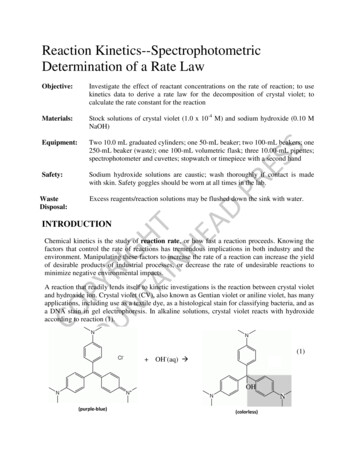
Wavelength scanning pixel super-resolutionW Luo et al2to recover the phase of the optical wavefront in digital holography.Previous studies26–29 have demonstrated a phase retrieval technique bytuning the wavelength of the illumination for non-dispersive objects.This wavelength-diversity-based phase retrieval approach requires theillumination to be tuned over a rather large spectral range26–29 (that is,460 nm) and assumes that the specimen maintains similar transmission properties across such a large bandwidth. Recently, a means ofusing wavelength diversity to provide a modest (for example, 16%)improvement in resolution has also been reported30. However, thismethod also assumes that the transmission properties of the specimenremain unchanged across an even larger spectral range of 4400 nm(that is, 460–870 nm), a condition that would not be satisfied forrealistic samples, including, for example, pathology slides and mostbiological specimens.In addition to significantly improving the resolution and the spacebandwidth product of the imaging system, our wavelength-scanningpixel super-resolution approach over a narrow band also helps inrobust phase unwrapping to determine the optical path lengthdifferences between the sample and surrounding mediumaccurately31–33. For samples in which the optical path length is longerthan the wavelength, the obtained phase map will be wrapped. Inparticular, when the object has sharp boundaries, such errors may bedifficult to correct using state-of-the-art phase unwrapping techniquesbased on a single wavelength reconstruction34–37. By making use of allthe illumination wavelengths in our super-resolution approach, wealso demonstrated robust phase unwrapping in our high-resolutionmicroscopic phase images, correctly revealing the optical path lengthinformation of the samples.In addition to lens-free holographic imaging techniques, weexperimentally demonstrated that the same wavelength-scanning-the use of any lateral shifts or displacements. In this technique, thespecimen is sequentially illuminated at a few wavelengths that aresampled from a rather narrow spectral range of 10–30 nm. Comparedwith sub-pixel displacement or lateral shift-based super-resolutiontechniques, wavelength scanning introduces a uniform resolutionimprovement across all the directions on the sample plane andrequires significantly fewer raw measurements to be made. Makingfewer measurements without sacrificing performance could greatlybenefit high-speed wide-field imaging, field-portable microscopy andtelemedicine applications, which are all sensitive to data transmissionand storage.We demonstrated the effectiveness of this new wavelengthscanning-based pixel super-resolution approach using lens-free holographic microscopy (Figure 1) to improve the resolution and theeffective numerical aperture (NA) of a unit magnification imagingsystem by a factor of 4 in all directions. Using 12 differentillumination wavelengths between 480 and 513 nm, we achieved ahalf-pitch resolution of 250 nm and an effective NA of 1.0 across alarge FOV of 420 mm2, which constitutes a space-bandwidth productof 41 billion. At the heart of these results is an iterative pixel superresolution algorithm that was developed to obtain high-resolutioncomplex (that is, phase and amplitude) reconstructions from undersampled (that is, pixelated) lens-free digital holograms acquired atdifferent wavelengths.In the previous work, wavelength diversity in illumination has beenmainly utilized for two general purposes. The first has been to obtaincolor or spectral information of a sample13–25; wavelength-dependenttransmission, absorption or scattering features of the specimenenhance the contrast of the image and might reveal chemical and/orphysical properties of biological samples. The second purpose has beenabWavelength scanning range: 10–30 nmLens-free hologramsBefore samplingAngle range:–40 :10 :40 2-axisAfter sampling(image sensor output) 530 nm 5–10 cm 533 nmyxObject plane(z 0)z 100 μm –1 mm 536 nmVertical scanSensor plane(z z 0)2 mFigure 1 Optical setup of wavelength-scanning pixel-super resolution. (a) A lens-free holographic on-chip microscope using wavelength-scanning pixel superresolution. A fiber-coupled tunable light source is placed above the object. When performing pixel super-resolution, the wavelength is scanned within aspectral range of 10–30 nm. Multi-height and synthetic aperture imaging configurations are also integrated into this setup to enable phase retrieval. (b) Lensfree holograms at different wavelengths before and after digital sampling at the image sensor plane.Light: Science & Applicationsdoi:10.1038/lsa.2016.60
Wavelength scanning pixel super-resolutionW Luo et al3based super-resolution framework can also be applied to improve theresolution of lens-based imaging systems with the introduction of aslight defocus, making this work broadly applicable to variouscoherent or partially coherent wide-field imaging modalities that arelimited by pixelation or undersampling. Therefore, we believe that thisnew wavelength-scanning-based super-resolution technique wouldlargely benefit wide-field and high-throughput microscopy applications that require enhanced space-bandwidth products.MATERIALS AND METHODSOptical setupAs depicted in Figure 1, the optical setup of the lens-free microscopeconsists of three major components: a light source, an image sensorarray, and a specimen. A fiber-coupled, wavelength-tunable lightsource (WhiteLase-Micro, model VIS, Fianium Ltd, Southampton,UK) is used to perform the wavelength scanning. During the imagingprocess, the central wavelength of the source is scanned within aspectral range of 10–30 nm (for example, from 498 to 510 nm) with astep size of 3 nm. The spectral linewidth of illumination at eachwavelength is 2 nm, and the power of the light source is adjusted to 20 μW. The image sensor chip is a color CMOS sensor chip with apixel size of 1.12 μm manufactured for cellphone camera modules(IU081, Sony Corporation, Tokyo, Japan). During the imaging process,the specimen is mounted on a transparent substrate and placed 100–500 μm above the image sensor chip. We merged our wavelengthscanning-based pixel super-resolution approach with both multiheight11 and synthetic aperture imaging12 configurations to obtainphase-retrieved, high-resolution reconstructions of the specimen. Forsynthetic-aperture-based imaging12, the fiber outlet of the light sourceis mounted on a rotational arm (PRM1Z8, Thorlabs, Newton, NJ,USA), and the image sensor is placed on a stage that can rotate over ahorizontal plane. Therefore, the incident light can be set to arbitraryillumination angles, which is required for the synthetic apertureapproach. For multi-height-based phase retrieval9,11, the incrementalheight change between the image sensor and the specimen is enabledby a mechanical positioning stage (MAX606, Thorlabs). The imagesensor is mounted on this mechanical stage, whereas the specimen isheld by a three-dimensional-printed sample holder. After completingimage capture for each height, the stage lowers the image sensor by 10–15 μm on average before the image capture for the next height starts.During the imaging process, all the necessary steps, including thewavelength scanning of the light source, multi-height and syntheticaperture-related scans and data acquisition using the image sensor chipare automated by a custom-written LabVIEW code (Version 2011,National Instruments, Austin, TX, USA).Wavelength calibration and dispersion compensationWavelength calibration of our light source is achieved using an opticalspectrum analyzer (HR2000 , Ocean Optics, Amersham, UK). Theintensity-weighted average wavelength of each measured spectrum isconsidered as our illumination wavelength. To achieve optimalresolution, the refractive index of the glass substrate (100 μm,N-BK7, Schott AG, Mainz, Germany) at each wavelength is alsocorrected using the dispersion formula for borosilicate glass.Sample preparationThe grating lines used for resolution quantification are fabricated on a 100 μm glass slide (N-BK7, Schott AG) using focused ion beammilling. Unstained Papanicolaou (Pap) smear slides are preparedthrough the ThinPrep method (Hologic, Inc., Marlborough, MA,USA). The blood smear samples are prepared using EDTA(ethylenediaminetetraacetic acid) anticoagulated human blood andstained with Wright’s stain38.Mathematical formalism of wavelength-scanning pixelsuper-resolutionWe assume that the specimen is a thin object mounted on a planeparallel to the image sensor chip and that the specimen is sequentiallyilluminated by multiple wavelengths {λk}. At a given wavelength λk, theobject wave can be written as ok(x, y) 1 sk(x, y), where sk(x, y)represents the scattered object wave, immediately at the exit of theobject plane (z 0, in Figure 1a). The two-dimensional Fouriertransform of ok(x, y) can be written as Ok(fx, fy) δ(fx, fy) Sk(fx, fy).At the image sensor plane (z z0 in Figure 1a), the Fourier transformof the intensity distribution, ik(x, y), can be written as (seeSupplementary Information for details): þ SSkI k ¼ d þ T k ? Sk þ T k ? Skð1ÞTo simplify our notation, we hide the expression of the variables forspatial frequencies (fx, fy), and the superscript ‘ ’ represents ( fx, fy). On the right-hand side of Equation (1), the first item, δ,represents the background intensity; the second and third items areconjugate holographic terms, which represent the interference of thescattered object wave with the background wave at the sensor plane.The fourth item is the self-interference term, which can be considerednegligible for weakly scattering objects. The expression for Tk can bewritten as follows: T k ðf x ; f y Þ ¼ H k f x;k ; f y;k ? H k f x þ f x;k ; f y þ f y;kð2ÞWhere Hk(fx, fy) is the free space transfer function, and the frequencyshifts fx,k and fy,k are determined by the illumination wavelength andthe incident angle (refer to the Supplementary Information fordetails). After the object intensity is sampled by an image sensorarray with a pixel pitch of Δx and Δy, the discrete Fourier transformof the sensor’s output can be expressed as follows39:I sampled; k ¼ uvI pix; k f x ; f y DxDy7 1;:::Xu; v¼0;ð3Þwhere u and v are integers and fx and fy are discrete spatial frequencyvalues. Note that Ipix,k(fx, fy) Ik(fx, fy)·Pk(fx, fy), where Pk(fx, fy)represents the Fourier transform of the pixel function, that is, thetwo-dimensional responsivity distribution40 within each pixel: pk(x, y).Variables u and v represent the order of spatial aliasing due topixelation, and (u, v) (0,0) corresponds to the non-aliased real (thatis, target) signal. The periodic nature of the discrete Fourier transformenables us to extend the expression of Isampled, k to a broader frequencyspace by upsampling (Figure 2). Based on these definitions, we canexpress the undersampled or pixelated lens-free hologram at a givenwavelength λk as follows:I sampled;k¼ iXh duv þ T uv; k ? Suv; k þ T þ SSuv; k ? P uv; kuv; k ? Suv; ku; vð4ÞThe non-aliased target signal ok(x, y) or its spatial Fourier spectrumcan be obtained under (u, v) (0,0), that is, δ00 S00, k, which can bedoi:10.1038/lsa.2016.60Light: Science & Applications
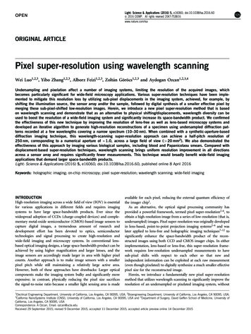
Wavelength scanning pixel super-resolutionW Luo et al4Stage I: generation ofhigh-resolution initial guessHigh-resolution initial guessStage II: iterative artifactelimination & phase retrievalFFT of high-resolutioninitial guessAperture No. kHigh-resolution, phaseretrieved reconstructionsAperture No. k 1IFFTNyquist window of rawmeasurements4Upsample,back-propagate &summationRaw measurement No. kUpdate in frequency domainForward1 propagation Object planeΣSensor plane2FFT of raw measurement No. kBack-3 propagationAmplitude update usinglow-resolution measurementsRaw pixelpitchFFTSub-pixelFigure 2 Reconstruction algorithm for wavelength-scanning pixel super-resolution, integrated with multi-height or synthetic-aperture-based lens-free phaseretrieval. Refer to the Materials and Methods section for further details. The fourth column shows super-resolved and phase-retrieved reconstruction of thespecimen. FFT, fast Fourier transform; IFFT, inverse fast Fourier transform.written as follows: d00 þ S00; k ? P 00; k ¼ T 00; k ? I sampled; k T 00; k ? T 00; k ? P 00; k ? S00; k X T 00; k ? T uv; k ? P uv; k ? Suv; k þ T 00; k ? T uv; k ? P uv; k ? Suv; kua0; va0 XT 00; k ? duv ua0; va0Xu; v¼0; 7 1;:::T 00; k ? P uv; k ? SSuv; kð5ÞOn the left side of Equation (5), we retain the pixel function P00, k,which can be removed later in the last step of the image reconstruction, using, for example, spatial deconvolution with a Wiener filter41, asillustrated in ref. 40. Equation (5) also shows that to obtain the nonaliased object at (u, v) (0,0), one needs to eliminate or subtract fourterms from the upsampled and back-propagated holographic term (thatis, T 00; k ? I sampled; k ). To this end, the first item to eliminate, T 00; k ? T 00; k ? P 00; k ? S00; k , is the twin image noise, a characteristicartifact of in-line holography. The second term in Equation (5), whichcontains Suv; k and S uv; k (ua0, va0) in the summation, represents theeffects of spatial aliasing and undersampling for both the real and twinimage terms. The third item, which contains duv in the summation, isthe periodic background artifact generated during the upsamplingprocess, and the last item is the self-interference term and itsupsampling related artifacts. Starting with the next sub-section, we willdiscuss a two-stage reconstruction algorithm for eliminating all four ofthese items listed on the right side of Equation (5) using wavelengthscanning to enable super-resolved reconstructions of complex (that is,phase and amplitude) object functions.Reconstruction Stage 1: generation of a high-resolution initial guessof the specimen using wavelength diversityAs depicted in Figure 2, the reconstruction of the specimen imageinvolves two stages. First, it should be noted that in Equation (5) theLight: Science & Applicationsfunctions {T 00; k ? T uv; k (u 0, v 0)} have complex values with unitamplitude, and their phases are highly sensitive to changes inwavelength (see the Supplementary Information for details). Therefore, when the illumination wavelength (λk) is scanned over Kdifferent wavelengths that are uniformly spread across a narrowbandwidth, the set of functions {T 00; k ? T uv; k (u 0 or v 0)} can beconsidered rotating unit vectors, and by summing all these rotatingvectors as a function of wavelength, we obtain the following: K X T 00; k ? T uv; k ? Puv; k ooK ? Puv; k ð6Þ k¼1 This expression indicates that by summing all the back propagations atdifferent wavelengths (for example, over a narrow spectral range of10–30nm), the reconstructed image, that is, d00 þ S00; k or d00 þ S00; k ? P00;k , can be significantly enhanced, whereas the spatialaliasing and undersampling-related terms with T 00; k ? T uv; k will beconsiderably suppressed. Therefore, in this first stage of our reconstruction process, we generate a high-resolution initial guess of thespecimen by summing all the upsampled and back-propagated rawmeasurements, that is, low-resolution diffraction patterns. We subtractthe artifact items {δuv (u 0, v 0)} before the back-propagation step tocreate a cleaner image.It should be noted that modifying Equation (6) into a weightedaverage at each spatial frequency point could achieve better suppression of spatial aliasing and undersampling-related artifacts. However,using our current computation platform, which is based on a centralprocessing unit, the search for optimal weighting factors at eachfrequency point will significantly increase the total computation time.Therefore, in this proof-of-concept implementation, we choose asimpler summation approach to minimize the computation time forthe generation of the initial object guess. The spatial aliasing anddoi:10.1038/lsa.2016.60
Wavelength scanning pixel super-resolutionW Luo et al5undersampling-related artifacts of this initial guess will be furthereliminated and cleaned up during the second stage of our algorithm,as will be detailed next.Reconstruction Stage 2: multi-wavelength-based iterative pixelsuper-resolution and phase retrievalThe second stage of our numerical reconstruction involves an iterativealgorithm, which contains four sub-steps in each iteration:(1) Knowing each raw measurement’s corresponding wavelengthand incidence angle, we apply the corresponding plane wave illumination on the initial guess of the specimen (from Stage 1, discussedabove) and propagate the optical field from the object plane to theimage sensor plane using the angular spectrum approach42.(2) The amplitude of the high-resolution field on the image sensorplane is updated using the low-resolution measurement at thecorresponding wavelength. To this end, the intensity of the highresolution field is convolved with the image sensor’s pixel functionand downsampled to the same grid size as the pixelated rawmeasurement. The difference between the raw measurement and thedownsampled intensity map is considered a low-resolution ‘correction’ map for each illumination wavelength. A high-resolutioncorrection map can then be generated by taking the Kroneckerproduct of this low-resolution map and the pixel function. To performa smooth update, this high-resolution correction map is added to thehigh-resolution intensity distribution with a relaxation parameter,typically set to 0.5 (see the Supplementary Information for details).After the smoothed update, a Wiener deconvolution filter thatincorporates the image sensor’s noise level is applied to this updatedintensity distribution. The square root of this filtered high-resolutionintensity distribution is then applied to the amplitude of the field onthe sensor plane while the phase map is kept unaltered.(3) This updated field is then back-propagated to the object plane.(4) The back-propagated field is used to update the transmissionfield on the object plane. This update is performed in the frequencydomain (Figure 2) within a circular area whose center is determinedby the corresponding illumination wavelength and angle. The radius ofthis circle is defined by the boundary within which all the spatialfrequencies experience an attenuation of less than 3 dB after propagation in the spatial domain. This update on the object plane is alsosmoothed using a relaxation factor of 0.5. After the update, thephase of the field on the object plane is converted to an optical pathlength map, and its amplitude is directly used as the transmission ofthe object.The four steps described above are performed for every raw (that is,undersampled) measurement captured by the image sensor array. It isconsidered one iteration cycle when each one of the raw measurements has been used for amplitude update. Typically after 5–10iteration cycles, the reconstruction converges. The convergence condition for the iteration is defined as follows43: itr ð7Þ SSEavg SSEitr 1avg oεwhere SSEitravg is the sum-squared error between the raw measurementand the downsampled intensity map43, ‘itr’ is the iteration number,and ε is a convergence constant determined by the noise level of theraw (that is, undersampled) measurements.Phase retrieval using multi-height and synthetic aperturetechniquesMulti-height9,11,44–46 and synthetic aperture12 techniques have beenproven to be robust phase retrieval methods for lens-free on-chipimaging. In previously reported lens-free reconstructions9,11,12, pixelsuper-resolution and phase retrieval are carried out sequentially: ateach height or illumination angle, lateral shift-based pixel superresolution is first performed to obtain high-resolution diffractionpatterns on the image sensor plane. These super-resolved diffractionpatterns are then used by an iterative phase retrieval algorithm, inwhich wave propagations between the object plane and the imagesensor plane are executed repeatedly9,11,12. However, in wavelengthscanning-based pixel super-resolution, raw measurements are essentially undersampled versions of different holograms. Therefore, wechoose to use the same iterative algorithm detailed in the previoussub-section (that is, Reconstruction Stage 2) to realize resolutionenhancement and phase retrieval altogether. More specifically, in themulti-height configuration, the specimen is illuminated sequentially ateach wavelength, and the corresponding lens-free holograms arecaptured before the vertical scanning stage moves the sample or theimage sensor to the next height. Each height will be labeled with indexl; therefore, all the measurements {Isampled, k} and the correspondingtransfer functions {Hk} and {Tuv, k} that are used in the previousderivations can be relabeled as {Isampled, kl}, {Hkl} and{Tuv, kl}, respectively. During the numerical reconstruction process,all the raw holograms are upsampled, back-propagated, and thensummed together to generate the high-resolution initial guess at agiven height. In Stage 2 of our reconstruction algorithm, theaforementioned four-step process is applied to each raw measurement.The same set of operations and processing also apply to the syntheticaperture technique12, except that index l now refers to each illumination angle instead of sample height.In general, for pathology slides such as blood smears and Papsmears, the optical path length difference between the specimen (thatis, biological tissue) and the medium (that is, air or the sealing glue) israther small. Under these circumstances, phase unwrapping is not aconcern; therefore, in the phase recovery process, we can use ascrambled order of {Isampled, kl} in each iteration cycle. However, whenworking with samples with larger optical path length differences, suchas grating lines carved into a glass substrate, one extra step, that is,phase unwrapping, must be added after the reconstruction, and theorder of iterations must be modified accordingly, which will bedetailed in the next sub-section.Multi-wavelength phase unwrappingA robust phase unwrapping algorithm requires high-resolution andphase-retrieved reconstructions at multiple wavelengths; therefore, wedivide the raw measurements into subsets, in which the wavelengthsare identical or very similar (for example, Δλ 5 nm), and performthe four-step reconstruction process previously discussed (as part ofthe Reconstruction Stage 2) on each subset separately. For example,reconstruction number 1 uses subset {Isampled, kl k 1, l 1, L}, No.2 uses {Isampled, kl k 2, l 1, L} and so on. When the iterations forall these subsets are completed, we obtain high-resolution (that is,super-resolved) phase-retrieved reconstructions at multiple wavelengths, that is, {Ok}, whose phase maps {ϕk,wrapped} need unwrapping.Using these wrapped phase maps {ϕk,wrapped} at multiple wavelengths,we perform phase unwrapping to accurately reveal the optical pathlength differences between the specimen and the surroundingmedium. Assuming that the optical path length difference is ΔL(x,y), the phase distribution at the object plane at each wavelength can bewritten as ϕk(x, y) 2π·ΔL(x, y)/λk. The wrapped phase can thus beexpressed as ϕk,wrapped (x, y) ϕk(x, y) 2Nπ, where πoϕk,wrapped π and N is an integer. These resulting wrapped phase maps {ϕk,wrapped} that are generated through super-resolved and phase-retrieveddoi:10.1038/lsa.2016.60Light: Science & Applications
Wavelength scanning pixel super-resolutionW Luo et al6Reconstruction from singlemeasurement (z 320 μm)abSingle measurement at 510 nmSmallest resolved half-pitch: 0.98 m5 shifted measurementsHologramSmallest resolvedshift tablehalf-pitch: 0.69 msensorpixel7 m 00Wavelength scanningpixel super-resolution (z 320 μm)Lateral shift-based pixel super-resolution (z 320 μm)6.5 m0cd9 shifted measurementsHologramshift tableSmallest resolvedhalf-pitch: 0.62 m5 wavelength measurements(498 nm : 3 nm :510 nm)Smallest resolved half-pitch: 0.62 msensorpixel5 m 04.5 m4 m 004 m04 m04 mFigure 3 Resolution improvement introduced by wavelength-scanning pixel super-resolution. (a) Reconstruction from a single raw measurement captured byan image sensor chip with a pixel pitch of 1.12 μm. (b, c) Lens-free reconstructions using lateral shift-based pixel super-resolution. b and c are reconstructedusing super-resolved holograms synthesized from five and nine sub-pixel-shifted raw measurements, respectively. The corresponding sub-pixel shifts of theraw measurements are marked within the hologram shift tables. (d
synthetic-aperture-based imaging12,thefiber outlet of the light source is mounted on a rotational arm (PRM1Z8, Thorlabs, Newton, NJ, USA), and the image sensor is placed on a stage that can rotate over a horizontal plane. Therefore, the incident light can be set to arbitrary illumination angles, which is required for the synthetic aperture .