Transcription
Mechanical Power TransmissionFundamentalsCourse No: M03-018Credit: 3 PDHRobert P. Tata, P.E.Continuing Education and Development, Inc.9 Greyridge Farm CourtStony Point, NY 10980P: (877) 322-5800F: (877) 322-4774info@cedengineering.com
Mechanical Power TransmissionFundamentalsCopyright 2012Robert P. TataAll Rights Reserved
Table of ContentsSubjectGear TrainsPlanetary GearsDifferential GearsGearboxesMulti-Speed GearboxesCouplingsClutchesBelts and PulleysChains and SprocketsPage2681114192326311
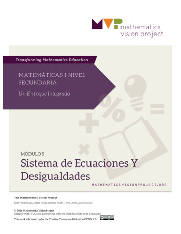
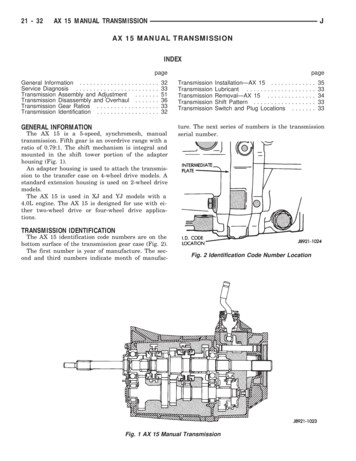
Gear TrainsGear trains are multiple sets of gears meshing together to deliver power andmotion more effectively than can be accomplished by one set of gears. Figure 1shows the various types of gears that can be used in a gear train. Gears 2 and 3can be either spur or helical gears and are mounted on parallel shafts. Gears 4and 5 are bevel gears that mount on shafts that are 90 apart. Gears 6 and 7comprise a worm gear set and mount on shafts that are at 90 but are nonintersecting. Worm gears have a high ratio and can be non-reversing.Figure 2 depicts a simple gear train at the top and a compound gear train at thebottom. The simple gear train consists of four in-line gears in mesh. Thecompound gear train consists of the same four gears, except two are located onthe same shaft. The overall ratio of the simple gear train is the product of thethree individual ratios and is as follows:n equals the rpm and N equals the number of teeth in the respective gears. Whencancelling out like quantities, the equation can be reduced to the following:Suppose Gear 5 has 64 teeth and Gear 2 has 16 teeth, than the overall gear trainratio would be 4 to 1. If Gear 2 is considered the driving member, the simplegear train in Figure 2 is a speed reducing gear train. If the rpm of Gear 2 is 400,the rpm of Gear 5 is 100. Gears 3 and 4 are called idler gears since they have noeffect on the overall gear train ratio.The equation for the overall ratio of the compound gear train is the product ofthe two individual ratios and is as follows:Assuming that the same four gears are used and that Gear 3 has 32 teeth andGear 4 has 48 teeth, the overall ratio for the compound gear train is:2
The following can be said about using compound gear trains over simple geartrains:1) More ratios can be obtained.2) The design is more compact.3) There is one less shaft.Figure 13
Figure 2ShaftGear4
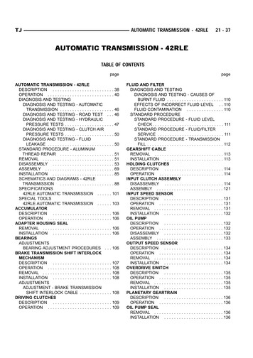
Figure 3 shows that very large Gears 6 and 7 are needed if a simple gear train isnot used. The effect is even greater for a compound gear train.Figure 35
Planetary GearsPlanetary gears consist of a set of gears as shown in Figure 4. The sun gear issurrounded by one or more planet gears which ride inside a ring gear. Theplanet gears are supported by a carrier. Planetary gears are useful in that theycan deliver power over more than one path in a high ratio inline gear setting.One way to do this is to drive the sun gear, hold the ring gear from rotating, andtake off from the carrier on the opposite side of the set. The following equationis commonly used to calculate the speed relationships with planetary gear sets:nc is the carrier rpm.Ns is the number of teeth in the sun gear.Nr is the number of teeth in the ring gear.ns is the sun rpm.nr is the ring gear rpm.Let us assume that in Figure 4 the number of teeth in the sun gear equals 48, thenumber of teeth in the stationary ring gear is 112, and the input speed to the sungear is 100 rpm. Using the above formula, we can now calculate the output rpmof the carrier as follows:nc 30The planetary gear set of Figure 4 can deliver over a 3/1 speed reduction whendriving the sun and taking off from the carrier. It can be shown using thisrelationship, that there are other possibilities planetary gears have in deliveringvarious speed ratios. Planetary gears are used in wind turbine gear boxes. Thesegearboxes speed up the low rpm rotor rotation to a higher speed generatorrotation.6
Figure 47
Differential GearsFigure 5 shows the arrangement of the gears in the center section of anautomotive drive axle. Power is transmitted from the pinion gear to the ringgear. From there it travels through the differential gears to the two output shafts.As long as the vehicle is traveling in a straight line, the four differential gearsrotate as a unit and do not rotate with respect to each other. When a vehicletravels around a corner, the differential gears rotate at different speeds allowingthe outer wheel to travel further than the inner wheel so the tires do not skid onthe pavement surface. A disadvantage of the differential gear system is thatwhen one wheel is on a slippery surface, all the power is sent to that wheelmaking it slip rendering the vehicle immobile. Some vehicles have slip clutchplates mounted behind the differential gears which allows the vehicle to propelitself using the one wheel that is still on a tractive surface. Figure 6 shows thecross section of a complete automotive drive axle.The following relationship holds true for the differential gears:nr is the rpm of the ring gear.Nlo is the rpm of the left output shaft.Nro is the rpm of the right output shaft.Let us assume that the pinion gear has 30 teeth and that the ring gear has 90teeth. With the left hand wheel of the vehicle raised up and free to rotate and theright hand wheel resting firmly on the pavement, what is the rpm of the lefthand wheel when the pinion gear rotates at 1200 rpm? The rpm of the ring gearis as follows:Using the above relationship, the rpm of the left hand wheel which is free torotate is as follows:8
Figure 59
Figure 610
GearboxesGearboxes contain one or more pair of gears inside a housing which has aninput shaft and one or more output shafts. The output shafts may be located onthe sides or at the back of the gearbox. Gearboxes contain a gear lubricant, aresealed, and usually operate maintenance free. Connected to the input shaft is ahigh speed power source such as a motor and connected to the output shafts aredevices which generally use lower rpms and higher torques to perform aparticular task. The device may include a machine tool, a conveyor, an elevator,or the wheels of an automobile.Figure 7 has a worm gearbox at the top and a bevel gearbox at the bottom.Worm gearboxes are generally high reduction devices with ratios ranging from5/1 to 60/1 for single reduction units such as shown in Figure 7 to 3600/1 fordouble reduction units. Because of the high amount of sliding that occurs at themesh, worm gears operate at efficiencies below that of other types of gears. Tominimize this effect, the gear is usually made of a material with a lowcoefficient of friction such as bronze. Worm gears can be made to be nonreversing by keeping the lead angle of the worm thread low.Figure 7 has a bevel gearbox at the bottom. Bevel gearboxes have input andoutput axes 90 apart like worm gearboxes; however, bevel gearbox axesintersect as opposed to worm gearbox axes being offset. Bevel gearboxesgenerally have lower ratios than worm gearboxes and can be used as speedincreasers as well as speed reducers. Bevel gearboxes having all steel gears candeliver more horsepower than worm gearboxes with bronze gears. Spiral bevelgears are stronger and quieter than straight bevel gears but are less efficient.11
Figure 712
Figure 8 has a double reduction gearbox on top and a gearbox-motorcombination unit on bottom. The double reduction gearbox can give twice theratio as a single reduction gearbox in a slightly larger package. It featureshelical gears for quieter, more powerful operation over spur gears. The motorgearbox unit is an integral package that features a double reduction helicalgearbox directly attached to a drive motor. Integral motor mounting featuresexcellent alignment with the gearbox input shaft for smooth, vibration-freeoperation.Figure 813
Multi-Speed GearboxesThe manual transmission of an automobile is a multi-speed gear box. Itincorporates varying the means of reduction through the gearbox in steps forcontrolling vehicle acceleration and deceleration. Figure 9 has a schematic of athree-speed automatic synchromesh manual transmission. It is shown in theneutral or non-drive position. There are three shafts and three sets of gears. Theshafts include the input shaft (1), the counter shaft (2), and the output shaft (3).The gears include the counter shaft drive gears (4) which are always engaged,the first gearset (5) where the upper gear is shown slid out of mesh, and thesecond gearset (6) in which the upper gear spins freely on the shaft. Thesynchromesh clutch (7) is used for second and third gear and is shown in thecentral or neutral position.Figure 10 shows the four shift positions of the manual transmission shown inFigure 9. The top schematic in Figure 10 has the transmission in the neutralposition which is what is seen in Figure 9. In the neutral position, the input shaft(1) drives the counter shaft (2) which spins freely. The second schematic showsthe transmission in first gear. Through a manually operated lever system, theupper first gear (5) is slid into mesh with the lower first gear allowing power tobe delivered to the output shaft (3). The next schematic has the transmission insecond gear. The upper first gear (5) is slid out of mesh and the synchronizerclutch (7) positively connects the upper second gear (6) to the output shaft (3)allowing power to be transmitted through the transmission.Figure 11 shows the operation of the synchronizer with the second gear. Theupper figure shows the synchronizer rotating with the output shaft next to theupper second gear which is free to spin on the same output shaft. The nextfigure shows the synchronizer moved to the right until the conical surfaces ofthe synchronizer and the gear touch. This action causes the second gear and theoutput shaft to rotate as a unit. The third figure has the synchronizer moved allthe way to the right until the teeth of the two members mesh. This mesh provesto be a smooth engagement since the two are rotating at essentially the samespeed.14
Figure 915
Figure 1016
Figure 1117
The last schematic of Figure 10 shows the synchronizing clutch (7) positivelyconnecting the input shaft (1) directly to the output shaft (3) resulting in directdrive through the transmission. The synchronizing clutch is moved to the leftcreating the same action that is described above.Nominally the ratios for gears are 2.75 for first, 1.65 for second, 1.0 or directdrive for third, and 3.25 for reverse which incorporates another shaft not shownin the figures. There are manual transmissions with more than three speedswhich incorporate additional gears and synchronizing clutches.18
CouplingsA coupling is a device that connects two shaft ends together so that power maybe transmitted through the juncture. There is a rigid coupling, a flexiblecoupling, and a fluid coupling. The simplest type is a flanged coupling which isclassified as a rigid type. Since it is rigid, it is used on shafts that are in goodalignment. The drawing at the top of Figure 12 is of a flanged coupling. Itconsists of two members which are loosely fitted on the shafts. When the twomembers are bolted together, tapered keys are wedged between the shaft and thecoupling locking the two shafts together. Flanged couplings can be assembled tothe shafts with loose fitting keys if the flanges are a press fit on the shaft.Flanged couplings are used in wind turbine drive trains.As previously mentioned, the flanged coupling is a rigid type that is used toconnect shafts that are closely aligned. For shafts that are not closely aligned, aflexible coupling is used. One such device is called a double slider coupling.The middle drawing of Figure 12 is of a double slider coupling. It can be seenthat it has a center piece with raised tongues 90 apart that fit in grooves in eachend piece. The end pieces are set screwed to the shafts while the center piece isfree to move to compensate for shafts that have offset and misalignment. Otherflexible couplings use center pieces with rubber, splines, or chains.For shafts with higher amounts of misalignment, a coupling called a universaljoint is used. Universal joints can be used on shafts with as much as 30 ofmisalignment. At the bottom of Figure 12 is a universal joint. It can be seen thatit has two opposing yokes that are connected to a cross-shaped center piece.Needle bearing (very small diameter roller bearings) are used at the fourconnection points to reduce friction. Universal joints that operate undermisalignment do not produce a constant angular velocity output. The outputvelocity fluctuates with each revolution causing unwanted vibrations. Thiseffect increases with increasing amounts of misalignment. For this reason,universal joints are frequently used in pairs which results in a constant velocityoutput.19
Figure 12A Rzeppa universal joint can also operate under a high degree of misalignment.Rzeppa joints are used in front drive shafts of front engine, front driveautomotive vehicles. The drawing at the top of Figure 13 shows the componentparts of a Rzeppa joint. There is a row of six balls in a cage that rides on theoutside diameter of the inner race and the inside diameter of the outer race(housing). The ball row operates at an angle halfway between the inner andouter races making the Rzeppa joint act like a bevel gear with balls rather than20
teeth doing the driving. Because of this operating characteristic, the outputvelocity of a Rzeppa joint is constant.Figure 1321
The third kind of coupling to go along with rigid and flexible couplings is thefluid coupling. An important use of fluid couplings is in automotive vehicleswhere it is mounted between the engine and transmission. The drawing of sucha unit is at the bottom of Figure 13. It can be seen that the main body is in theshape of a torus (donut). On the left is the input shaft to which the flywheel isattached. The flywheel is connected to the right side of the torus which containsa circular row of blades called the impeller. The impeller, when rotated, andwith the aid of centrifugal force, delivers oil across the narrow gap to the leftside of the torus where another row of blades called the runner is located. Theforce of the oil rotates the runner which is attached to the output shaft sendingpower to the vehicle drive wheels. The oil is then recirculated inward and backto the impeller to repeat the cycle.In the fluid coupling, power is not transmitted by mechanical means alone. Atone point in the cycle, all the power is transmitted by the oil across the narrowgap between the two rotors. This feature makes fluid couplings an excellentisolator of engine shock and vibration. Also, fluid couplings negate the need fora manually operated clutch in a vehicle.Since their inception, there have been a number of improvements made toautomotive fluid couplings which has increased their performance. Curvedblades on the impeller and runner have increased the amount of torquetransmitted between the two. The addition of a stationary row of blades calledthe reactor between the inner part of the impeller and the runner reduces thedrag on the impeller. Mounting the reactor on a one-way clutch eliminates aproblem when, during certain operational conditions, oil from the impellerimpinges on the back side of the reactor blades. With the addition of a numberof new features, automotive fluid couplings have now become to be calledtorque converters.22
ClutchesClutches are couplings that are used to engage and disengage the power that istransmitted between two connecting shafts. Positive drive clutches are designedto deliver full power without slippage. Friction clutches are designed to slip atsome predetermined torque setting. This allows smooth engagement anddisengagement and also protect against overload.The three jaw clutches shown at the top of Figure 14 is a positive drive unitdesigned to deliver full power in either direction of rotation without slippage. Itis shown in the fully engaged position. The left hand member is splined to theshaft while the right hand member is fixed to its shaft. For engagement ordisengagement, the left hand member is moved laterally by means of amechanical linkage that fits into the circular groove on its hub. Engagementspeed for a three jaw clutch is limited to approximately 10 rpm. Disengagementspeed is not limited for clutches with precision machined mating surfaces.Shown in the middle of Figure 14 is a spiral jaw clutch. Spiral jaw clutches arealso positive drive units but are designed to deliver power in one direction ofrotation only. For rotation in the opposite direction, units are made with thespiral reversed. Engagement and disengagement is similar to the square jawclutch. Maximum engagement speed is approximately 150 rpm. Disengagementspeed is not limited for clutches with precision machined surfaces.A basic drawing designed to show the fundamental principles of frictionclutches is shown at the bottom of Figure 14. It can be seen that there is afriction disc sandwiched between two rotating flanges. The left hand member issplined to the shaft while the left hand member is fixed to its shaft. A helicalspring acts on the left hand member supplying the force needed to deliver therequired torque. A mechanical linkage that fits into the rotary groove on the hubof the left hand member is used to provide the lateral movement necessary toengage and disengage the clutch. Engagement and disengagement speeds arenot limited with friction clutches as they are with positive drive clutches.23
Figure 1424
Friction discs make these functions perform smoothly and they also act as safetydevices by preventing system overload. Good disc materials are bronze and castiron. Friction clutches can have more than one disc to increase torque carryingcapacity.There are a number of clutches used in automotive vehicles. A friction clutchbased on the one on Figure 14 is used in manual transmissions. Automatictransmissions used hydraulically operated clutches to change gears. Automatictransmissions and torque converters have one-way clutches. One-way clutches,as the name suggests, allow rotation in one direction only. A roller or a sprag(flattened roller) ride up a ramp and lock into place preventing rotation in onedirection while allowing it in the other direction. There is an electronicallyoperated friction clutch that controls the air conditioning compressor. There is afriction clutch that controls the engine cooling fan in some automotive vehicles.A viscous fluid thickens as it heats up increasing the speed of the fan andcooling the engine. Clutches play a very important role in automotive vehiclepower systems.25
Belts and PulleysBelts and pulleys are used when the distance between shafts is too great to makeit practical to use gears. There are basically two kinds of belts: flat belts and Vbelts. Flat belts, as the name suggests, are wider and thinner than V belts whichhave a V shaped section. Both kinds are made of fabric which is impregnatedwith rubber. Belts are a quiet and efficient means of transmitting power and areable to absorb vibration. A cross section of a flat belt and pulley is shown at thetop of Figure 15 while a section of a V belt and pulley is shown at the bottom.Flat belt pulleys have a crown shaped outer surface which acts to keep the beltcentered. V belt pulleys have an internal angle slightly less than the belt. Thisproduces a wedging action of the belt into the pulley aiding traction. Generallyspeaking, flat belts are as efficient and can run as fast as gears, but deliver onlya fraction of the power. V belts are as efficient but can run only about 60% ofthe speed of gears and deliver a fraction of the power.V belts are used extensively in the front end of automobile engines to power thevarious vehicle accessories. At the top of Figure 16 is a diagram of a typicalvehicle engine accessory drive system. It can be seen that the engine crankshaftdrive pulley has one belt that drives the fan pulley and the power steering pulleyand a second that drives the fan pulley and the alternator pulley. The fan pulleyhas a third belt that drives the air conditioner pulley.At the bottom of Figure 16 is a diagram of a typical engine accessory drivesystem using a single poly V belt. At the top of Figure 17 is a cross sectionalview of a typical poly V belt. It can be seen that it is wider and thinner than astandard V belt and, as the name suggests, has a number of smaller V shapedgripping surfaces instead of the one larger surface characteristic of standard Vbelts. Poly V belts have a distinct advantage over standard V belts and arereplacing standard V belts in automotive engine accessory drive systems. Theyare stronger, more flexible, use smaller diameter pulleys, and last longer thanstandard V belts. The back of poly V belts acts like a flat belt and can be used todrive pulleys. Because of these advantages, the design package using poly Vbelts is smaller and simpler than that using standard V belts.26
Figure 1527
Figure 1628
Figure 1729
It is common practice to use a belt tensioner with poly V belts but theadvantages far outweigh any disadvantage this may have.At the middle of Figure 17 is a view of a cog belt. A cog belt, as can be seen,has the small V shaped ribs running across the belt rather than around the belt asthe poly V belt. Advantages of cog belts are greater flexibility and smallerpulleys than other belts. They are used when exact speed ratios between pulleysare required such as in automotive valve timing systems.30
Chains and SprocketsChains are used for lower speed applications when the shafts are too far apartfor gears and the torques are too high for belts. They are also used when exactspeed ratios are needed. At the bottom of Figure 17 is a cross sectional view ofa typical roller chain link assembly. The roller rotates on a bushing which fitson a pin. The roller link assemblies are held together by link plates on each side.The high efficiency and long life of roller chains is dependent on periodiclubrication of the link assemblies. Chains are used on engines, machines,conveyors, and heavy duty apparatus such as oil field and mining equipment.The sprockets for chains have teeth similar to gears. Sprockets with an oddnumber of teeth wear better than those with an even number of teeth. Therecommended number of teeth for smaller sprockets running moderate speeds isfrom 15 to 23. Sprockets running at low speeds can have as few as 7 teeth.31
Mechanical Power Transmission Fundamentals Course No: M03-018 Credit: 3 PDH Robert P. Tata, P.E. Continuing Education and Development, Inc. 9 Greyridge Farm Court