Transcription
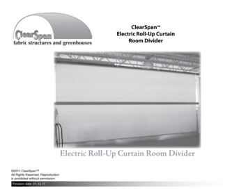
ClearSpan Electric Roll-Up CurtainRoom DividerElectric Roll-Up Curtain Room Divider 2011 ClearSpan All Rights Reserved. Reproductionis prohibited without permission.Revision date: 01.13.111
Important InformationREAD THIS DOCUMENT BEFORE YOU ASSEMBLE THE ELECTRIC CURTAIN ROOM DIVIDER.Thank you for purchasing this ClearSpan Electric Roll-Up Curtain Room Divider. These instructions include helpful hints and important information needed tosafely assemble and properly maintain the curtain and related components. Please read these instructions before you begin. If you have any questions duringthe installation, contact customer service.SAFETY PRECAUTIONS Wear eye, ear, and head protection during assembly. Wear gloves when handling the pipe, brackets, and cable. Use a portable GFCI when working with power tools and cords.WARNING: Exercise caution during installation. Strong winds can lift andblow the curtain during and after installation. Do not install the curtainduring windy conditions or when such conditions are expected. Wheninstalling inside a building, keep large doors closed until the curtain iscompletely installed and secured.REQUIRED TOOLSASSEMBLY PROCEDURERealizing that each room divider is custom-built for a specific opening, theseinstructions are presented to help ensure the proper assembly of the curtainand related components. Understand that you may need to adapt theseinstructions to safely and properly install your room divider. The informationpresented describes one way to assemble and install the divider.If you are not familiar with the installation of similar components and curtainsystems, you must obtain the services of a contractor experienced in thesesystems. Failing to follow these steps can result in an improper and unsafeinstallation of the curtain. The general steps outlining the installation processare as follows:1. Verify that all parts are included in the shipment. Notify Customer Servicefor questions or concerns.The following list identifies the main tools needed to install the electric curtainroom divider. Additional tools and supports may be needed depending onthe structure, location, and application. For safety and easier installation,we recommend at least two (2) people to assemble dividers up to 30' long;additional assistants are required for dividers 30' and longer.2. Read these instructions and all additional documentation included with theshipment before you begin. Tape measures and marker to mark locations. Chalk line or other means to level the curtain mounts.4. Install the curtain components in the order they are presented in theseinstructions. Adapt these instructions as needed to install your curtain. Variable speed drill (cordless with extra batteries works best) and variousdrill bits and a masonry bit (size depends on anchor bolt). Metal saw (for custom installations). Wrench and/or socket set. 5/16" Hex-head/Allen wrench for winch set screw Hammers and additional hand tools as needed. Ladders, work platforms, and other machinerydesigned to work safely at the height of the divider opening.23. Gather the tools, equipment, and assistants needed to install the electricroll-up curtain room divider.5. Read the care and maintenance information.UNPACK AND IDENTIFY PARTSThe following steps will ensure that you have all the necessary parts beforeyou begin.1. Unpack the contents and place where you can easily inventory theshipment. Refer to the Bill of Materials/Spec Sheets.2. Verify that all parts listed on the Bill of Materials/Spec Sheets are present.If you have questions or parts are missing, contact customer service.Revision date: 01.13.11
Important InformationPICTORIAL GUIDEThe following graphics and photos will help identify the different parts of theelectric curtain room divider system. Consult the Quick Start Guide at theback of this guide for additional details and diagrams. (Some parts are notshown.)FA19727/32" Eye ScrewFAW101 (1/4" x 2-1/4")Wedge AnchorCurtain PanelsThis room divider includes two (2) separate panels. Panelsare identical and can be installed in either the upper or lowercurtain position. May not apply to custom room dividers.FA4415BTek Screw109395Double PulleyFA4652#9-15 1-1/2" Woodgrip ScrewAS10261/8" Cable ClampAS1082 CableThimble109784Pulley BracketItems 109395 and 109784 are included to better align thecables from the winch to the room divider pulleys. They areused when the winch position differs from the examplesshown in this guide. Install the 109784 brackets at an anglethat best allows the pulley to remain fully seated in thebracket when the pulleys are under tension. See the note onPage 16 and the diagrams on Page 32 for additional details.ATTENTION: If winchincludes cable and a hook,remove these. They are notused for this roll-up curtain.108517Roll Bar109378Roll Bar Coupler110831Curtain MountingChannel110574Electric Winch100443 DriverRevision date: 01.13.113
PICTORIAL GUIDE (continued)The following graphics and photos will help identify the different parts of theelectric curtain room divider system. Consult the Quick Start Guide at theback of this guide for additional details and diagrams. (Some parts are notshown.)ATTENTION: The parts shown below are used only for room dividersthat are wider than 40'.1106514-Pulley Bracket (left)110394LCable Spool110394RCable Spool1106524-Pulley Bracket (right)1106502-Pulley Bracket(Use for dividers thatare 40' wide or shorter.)109837Mounted Single VerticalPulley1106552-Pulley TensioningBracket110384Roll Bar Coupler110396Roll Bar4110656Tensioning Cable Tie-OffBracketRevision date: 01.13.11
Important InformationCARE AND MAINTENANCEProper care and maintenance of your electric roll-up curtain room divider willhelp to ensure reliable service. The following items identify areas that must beperiodically checked to ensure that the components are maintained properly: Frequently check the curtain mount and mount support structure to verifythat all components are tight and in good condition. Check all fasteners to verify that they remain tight. Inspect the electric winch and related mounting components regularly.Tighten all bolts and mounts as needed. Verify that all connections and connectors are secure. Tighten these ifnecessary. Replace all broken or missing components immediately. Check the curtain to verify that it is in good condition. Repair or replace asneeded. Inspect frequently. Verify that all cables are in good condition. Replace worn or frayed cablesimmediately. Verify that all cable pulleys are in good shape. Inspect frequently to ensurethat all cables and related mounts are intact and functioning as designed. Verify that nothing rubs against the curtain or prevents it from opening andclosing as designed. When cleaning the panel, use tools that will not damage the material.Clean dirt and debris using mild soap and water. Do not use solvents.The diagrams below show two possible room divider positions. The stepspresented in this manual show a divider installed between two walls within abuilding (lower example).Flush (or Face) Mount Example: Top ViewWall of BuildingInteriorSidewallInteriorSidewallHeader andDivider PositionDivider Mounted Between Walls: Top ViewWall of BuildingGeneral InformationThe information contained within the pages of this guide describes one way toattach the electric curtain room divider to the inside of a typical building. Theexamples may not resemble the actual installation of your curtain.It is the customer's/installer's responsibility to use these diagrams asneeded to help with the installation of the actual electric curtain roomdivider. If you are not familiar with the installation of similar roomdividers, consult the services of a qualified contractor.InteriorSidewallInteriorSidewallHeader andDivider PositionUse the following diagrams, photos, and procedures to help assemble andinstall the electric roll-up curtain room divider.Revision date: 01.13.115
Important InformationSPECIAL ASSEMBLY NOTE: Customer-Supplied ComponentsHEADER (Room Dividers: Up to and including 40' Wide)Room dividers within this range require the installation of a 2" x 6" (minimumdimensions) header to mount the curtain channel and to support the cablepulleys. Length of this header is determined by the length of the opening.HEADER (Room Dividers: Greater than 40' Wide)For dividers greater than 40' in width, header must support a minimum of 3000lbs., and withstand the forces generated during the operation of the divider.Consult the services of a contractor experienced with the assembly andinstallation of similar systems to determine the best way to support yourroom divider.The customer is responsible for supplying the header and related mountingbolts that meet or exceed the requirements set forth above.Difficulties, damages, and injuries that arise from departing from therecommended installation procedures are not the responsibility of thecurtain system supplier.Seek the services of a qualified contractor or structural expert if you arenot familiar with the installation and operation of room dividers.CAUTION: Winch includes exposed moving parts and cable. Donot install in an area where people or livestock can contact thecomponents! If possible, construct a shield or border to protectoccupants.Winch is equipped with a manual switch for safety. Never bypassthis switch or alter it in any way. Doing so may damage winch andcurtain components and can cause serious injury.Always inspect the curtain panels and clear the area around thedivider before you raise or lower the curtain.CABLE ASSEMBLY INFORMATIONAll room divider systems include one (1) long and one (1) short main cableassembly: C18L1250K (125') and C18L6500K (65'). Do not cut these cablesuntil you have completely installed your room divider components and haveattached the cables to the winch and cable spools.Each length of cable is wrapped around the cable spool and cut to lengthduring the cable installation procedure shown in this guide.In addition to the above cables, room dividers longer than 40' include two(2) additional cables for the tensioning system. These cables (#AR3550)are of equal length and are installed after the other two cables are installed.DO NOT MIX CABLES DURING THE INSTALLATION PROCEDURES.INSTALL CABLES AS DESCRIBED IN THIS GUIDE.For proper operation and safety, cables cannot be spliced. Each lengthof cable must remain a single piece capable of passing through thepulleys and wrapping around the winch and cable spools.CONCRETE REQUIREMENTSRoom Dividers Greater than 40' WideRoom dividers of this size require a solid concrete floor on which to mountthe winch and secure the lower pulleys. Concrete must be a minimum of4" thick and in good condition. Inspect the mounting surface for cracks anddeterioration and repair as needed to create a sound surface capable ofwithstanding the forces created during the operation of the room divider.If no concrete floor is present, the customer must take the necessary stepsto create a suitable mounting surface. Consult the services of a structuralengineer or professional contractor experienced with the installation ofsimilar components and systems.NEVER STAND UNDER THE CURTAIN!6Revision date: 01.13.11
Installation1ATTACH ROLL-UP CURTAIN1. Determine curtain position on the building and install the customer-supplied header. (See the header note on the previous page.) With theheader installed, use a chalk line and level to create a line to mark the position of the curtain mounting channel. IMPORTANT: To ensureproper and even operation, the curtain must hang squarely from the mounting surface.2. Using the chalk line as a guide, take the first section of 110831 mounting channel and attach it to the header using the FA4652 wood screws.Use the 100443 nut driver to install the fasteners. For best results and to prevent curtain contact with the header, mount the 110831mounting channel near the bottom of the header. You must mount the channel squarely on header to ensure proper operation. If theheader is installed between walls as shown, do not install the two outside sections of 110831 channel. These are installed last.Customer-SuppliedHeader(See the headernote on theprevious page.)Building Frame110831 Curtain MountingChannel secured to header.Revision date: 01.13.117
Installation2ATTACH CURTAIN TO THE HEADERIn this example, the curtain is centered in the opening. If your divider requires a different position, consult the critical dimension shown below andadapt these instructions to your application. You must maintain the minimum clearances at each end of the panel as identified below.1. Spread one panel out on a clean surface to prevent damage and mark the center along an edge that includes the rope. See FIG. 1.2. Measure the length of the panel, and using the dimension below, determine where to position the center of the panel on the header, and markthat location on the header.3. Beginning at one end of the channel, slide the rope into the channel and align the marks (Figs. 2 & 3). The example below shows a dividerinstalled between walls. (See the examples on page 5.) The ends of the panel hang freely to allow for the installation of the roll-up curtain axledescribed on the next page. The remaining sections of 110831 are installed after installing the curtain axle.CenterFig. 1Rope Edge of PanelFig. 2110831Rope5-1/2"Minimum distance from the edge of the installed curtain to the wall is 5-1/2". Seethe Critical Dimensions diagram in the Quick Start section near the back of thisguide for additional details.ATTENTION: The divider shown above is installed between walls. The outersections of 110831 channel are installed after the roll-up curtain axle is installed.If your divider position is similar to the flush or face mounted example shown onpage 5, you can install the remainder of the 110831 channel before installing theroll-up curtain axle.Diagrams are not to scale. Curtain as seen from the front.8Fig. 3110831Photo above shows feeding the ropeand panel into the channel.Revision date: 01.13.11
Installation3INSTALL ROLL-UP CURTAIN AXLEAt this stage, different room dividers may require additional tools, lifts, and additional assistants depending on room divider size. Use the followinginformation as a general guideline when assembling and installing the roll-up curtain axle for your room divider.CAUTION: ROLL-UP AXLE COMPONENTS ARE HEAVY! EXERCISE CAUTION DURING ASSEMBLY. CONSULT THE SERVICES OF AQUALIFIED CONTRACTOR IF YOU ARE NOT FAMILIAR WITH THE INSTALLATION OF SIMILAR SYSTEMS, OR IF YOU DO NOT HAVE THESKILLS AND EQUIPMENT TO COMPLETE THIS PORTION OF THE ASSEMBLY. ASSISTANCE IS REQUIRED TO CONTINUE!1. With assistance, take all sections of the 110396 roll bar and position these end-to-end within the room opening to determine the installationpattern. Two roll bar sections include one end with coupler access holes (mating end) and one plain end (no access holes). Positionthese roll bars at far left and far right of the roll bar assembly with the plain end outward. See diagrams on Page 11 for details.2. Move to the back of the curtain panel and pull the loose ends of the upper curtain panel around to the back as shown.3. Slide the first section of 110396 roll bar onto the lower edge of the upper curtain panel. Use the width of the curtain and the length of eachroll bar to determine its position on the panel. To prevent damage, exercise caution when threading the panel into the channel of the roll bar.Refer to the Critical Dimensions diagram in the Quick Start section to determine end clearances when axle is fully assembled and installed.ATTENTION: Position the coupler access holes, presentat all mating ends of each roll bar section, as desired.Typically, these are positioned so they cannot be seenwhen the curtain is fully extended in the down (orclosed) position.Curtain4. Position a 110384 coupler so the anchor bolt headsare accessible through the access holes in the roll barand slide the coupler halfway (12") into the end of theinstalled roll bar.110384 CouplerAccess HolesSlide coupler halfway intothe roll bar end.Mating End of rollbar includes coupleraccess holes.CouplerAccess Hole12"Diagrams show the components from the back.Revision date: 01.13.11Diagrams are not to scale. Curtain as seen from the back.9
Installation3INSTALL ROLL-UP CURTAIN AXLE (continued)Upper Curatin Panel5. Take another section of 110396 roll bar, slide it onto the curtain as previouslydescribed, and slide it over the exposed end of the 110384 coupler.ATTENTION: Verify that the roll bar sections mate properly and that theangles of the curtain channels of the roll bar are aligned.6. Verify that both roll bars are in the desired position, adjust the coupler asneeded so all anchor bolt heads are visible in the access holes. (Use a prybar to reposition the coupler if needed. Insert an end into the access holesand gently pry against the bolt heads to realign the anchor bolts with theaccess holes.) The ends of the roll bars should be tight against each other.7. Tighten all coupler anchor bolts to secure the connection using a ratchet and9/16" socket.Mating EndMating EndMating EndPhoto above shows the back of the curtain axle ata coupler connection with the upper curtain panelinstalled. Mating ends of all roll bars include thecoupler access holes.Mating EndSTEP 6: Tighten the coupler anchor bolts.Diagrams are not to scale. Curtain as seen from the back.10Revision date: 01.13.11
Installation3INSTALL ROLL-UP CURTAIN AXLE (continued)8. Repeat the steps as needed to install the remaining roll barsections and related couplers. Be sure to maintain the requiredminimum clearances at each end during the installation of theremaining roll bars and couplers. Reposition the roll bars onthe upper curtain panel during the assembly to maintain theproper end clearances. Remember to install the two roll barsections with the plain ends outward at the far left and farright of the roll bar assembly. See lower right diagram.ATTENTION: As the roll bar sections are added, placetemporary supports under the assembled curtain axle forsupport. Number of supports depends on the length of thecurtain. Supports are removed before the installation of thelower curtain panel.Plain End(no holes)Mating EndPlain End(no holes)Plain End(no holes)Diagrams are not to scale. Curtain as seen from the back.Revision date: 01.13.1111
Installation4SECURE FREE ENDS OF UPPER CURTAIN PANEL1. Pull ends of the upper curtain panel around to the front as shown below.2. Take a section of 110831 channel, slide it onto the free end of the upperpanel, and secure it to the header using FA4652 wood grip screws.Review Section 1 if needed.NOTE: Trim the last sections of 110831 channel to length if needed.3. Repeat to attach the remaining section (or sections) of 110831 channel.4. Continue by installing the lower curtain panel.183011Curtain110831Step 1 & 2Step 3Diagrams are not to scale. Curtain as seen from the front.12Revision date: 01.13.11
Installation5INSTALL THE LOWER CURTAIN PANEL1. Remove all supports and allow the curtain axle to hang freely from the upper curtain panel and curtainmounting channel.2. Verify that the curtain and axle are level.IMPORTANT: The curtain will not roll up evenly if the assembly is not hanging evenly from the header. Ifnecessary, disassemble as needed to level the curtain and reassemble before continuing.3. Take the remaining curtain panel and carefully thread the end of one edge into the channel of the curtainaxle. See the Details diagram in the Quick Start section for additional information.4. Center the panel as needed to maintain the required clearances at each end and continue with the nextsection.ATTENTION: If it is possible that wind will blow theloose curtain, temporarily secure the curtain axleto the main building frame to prevent injury anddamage to the building or curtain components.Upper Curtain PanelDO NOT ALLOW A HANGING CURTAIN ANDAXLE TO REMAIN UNSECURED IF THERE ISANY CHANCE OF A SUDDEN GUST OF WIND.WINDY CONDITIONS OUTSIDE AN ENCLOSEDSPACE CAN AFFECT A CURTAIN IF SOMEONEOPENS ANY DOOR TO THE BUILDING. WHENIN DOUBT, ALWAYS SECURE A LOOSE CURTAINUNTIL FULLY INSTALLED.Lower Curtain PanelDiagrams are not to scale. Curtain as seen from the front.Revision date: 01.13.1113
Installation6110394L CableSpoolATTACH THE CABLE SPOOLS TO THE CURTAIN AXLEConsult the Details diagram in the Quick Start section before you begin foradditional information.1. Take the 110394L cable spool and slide it onto the left end of the curtain axleassembly.2. Consult the Critical Dimensions diagram in the Quick Start section of this guideand position the spool correctly on the 4" x 4" roll bar. Do not allow the installedspool to extend beyond the end of the roll bar.FA4415BScrewsSpoolMountingTab3. Using the FA4415B screws and100443 nut setter, secure thespool to the roll bar by driving thescrew through the spool mountingtabs and into the roll bar.4. Attach the remaining 110394Rcable spool to the other end of theroll bar as previously described.5. Continue by installing the lowerpanel trim rail as described in thenext procedure.110394L14Revision date: 01.13.11
Installation7Use 4 screws per coupler.INSTALL LOWER PANEL TRIM RAIL1093781. Take one section of the 108517 curtain channel roll bar and slide it onto the lower curtainpanel.2. Slide one 109378 coupler halfway into one end of the roll bar and secure in place usingtwo (2) FA4415B screws and the 100443 nut setter.3. Secure the coupler to the roll bar using two (2) more FA4415B screws installed oppositeeach other.4. Repeat this procedureas needed to install allremaining sections of the108517 curtain channelroll bar to finish the loweredge of the lower panel.CouplerarRoll BScrewSecure coupler to roll bar on each side using thescrews supplied with curtain and axle components.Upper Curtain PanelBe sure to secure eachsplice joint by using acoupler as shown.Curtain ChannelRoll BarLowerCurtainPanelSlide kederrope into theroll bar.108517Revision date: 01.13.1115
Installation8INSTALL WINCH: Choose Winch Position (left or right side of the room opening)The winch can be mounted in any location that allows for a clear, safe, and obstruction-free path for cables and pulleys. Location should alsoconsider traffic patterns around the divider area so the winch position does not interfere with these patterns or introduce a safety hazard.Four (4) wedge anchors (FAW101) are included to mount the winch to a concrete wall or floor. If substrate is not solid concrete, a suitablemounting surface must be created. If you are not experienced with the installation of similar systems or components, contact a qualifiedand experienced contractor for assistance. Consult the Winch diagram in the Quick Start section.Secure the winch in place and continue with the installation of the pulleys. Use a masonry bit and hammer drill to install the FAW101 wedgeanchors to secure the winch to the mounting surface.Consult the photos in the Quick Startsection of this guide for additionalwinch mounting suggestions.OPTION FOR DIVIDERS(40' WIDE AND UNDER)OPTION FOR DIVIDERS(WIDER THAN 40')ATTENTION: Pulley assembliesincluded with your divider are usedwhen the winch is mounted to aconcrete floor. See diagram to the rightand on the next page.Mounting locations that differ fromwhat is shown may require additionalpulleys and brackets to safely runthe cable to the winch. Two sets ofdouble pulleys and mounting brackets(109395/109784) are included to helpalign cables when winch positionchanges. The customer/contractoris responsible for determining howto run the cable when winch ismounted in an alternate location.Contact customer service to purchaseadditional brackets and pulleys ifneeded.REQUIRED: After installing the winch,consult the services of a qualifiedelectrician to connect the winch to apower source. Electrical requirementsare identified on the winch.16Winch: Left Side MountingOption for Dividers less thanor equal to 40'.Winch: Left SideMounting Optionfor Dividers 40'.Revision date: 01.13.11
Installation9aINSTALL PULLEY ASSEMBLIES: For openings up to and including 40' wide.If your divider is wider than 40', skip this procedure and continue with Procedure 9b on the next page. After installing the winch, usethe diagrams and photos below to mount the pulleys. FAH009B 1/4" x 4" carriage bolts are included to mount the 110650 bracketsto the installed header. If these fasteners do not work for your header, alternative fasteners can be purchased locally, or call yoursales representative for additional options.Consult the Pulley and Bracket Location Diagram in the Quick Start section for additional details.Upper TTENTION: Install pulleys so the outer edge of the pulleybracket is approximately 5-1/2" from the inside edge of the curtain.Revision date: 01.13.1117
9bINSTALL PULLEY ASSEMBLIES: For openings greater than 40' wide.After installing the winch, use the diagrams below to mount the pulley assemblies. FAH009B 1/4" x 4" carriage bolts areincluded to mount the 110651 and 110652 brackets to the installed header. If these fasteners do not work for your header,alternative fasteners can be purchased locally, or call your sales representative for additional options.Consult the Pulley and Bracket Location Diagram in the Quick Start section for additional details.CONCRETE NOTE:The lower pulleys require asolid concrete surface formounting. Minimum floorthickness is 4". Do not installwhere floor is cracked.ATTENTION: Install pulleys so the outer edge of the pulleybracket is approximately 5-1/2" from the inside edge of the curtain.Consult the services ofa qualified contractor foradditional information andsuggestions when a concretefloor is not present.A small concrete pad is notsufficient for a safe andreliable mounting surface!5-1/2"110651Installation steps for the lower 109837 pulley and 110656 tie-offbracket are the same for each side. Align pulley with the backpulley–closest to the header–of the upper pulley assemblies.Secure brackets to concrete using the FAW101 wedge anchors.See concrete note on this page.5-1/2"110652110656Diagram shows the 110655and 109837 bracketsbefore they are anchored toconcrete.18Revision date: 01.13.11
10INSTALL CABLE GUIDESAfter installing the pulleys, install the FA1972 cable guides. These guides help to keep thecable aligned with the pulleys when the roll-up curtain is opened and closed.Using the diagrams below, install the cable guides (FA1972) along the length of the header.Space the guides evenly at 60" intervals. Adjust spacing as needed for curtain lengths thatare not divisible by 5.FA1972 Cable GuideAlign cable guides with the installed pulleys. Wrap a string line around the pulleys, or use asection of cable pulled taut to properly align and install the guides.Cable PathHeaderUpper Curtain PanelInstalled CaRevision date: 01.13.11bleHeader19
Installation11CABLE ASSEMBLY INFORMATIONSECURE CABLES TO THE WINCHInstalling cables is the final step in the assembly of the roomdivider. Taking time to properly install, secure, and adjust thecables helps to ensure that your room divider opens and closesevenly. Complete the following steps to install the cables.1. Move to the winch and, using the winch control switches, rotatethe drum so the cable key hole is accessible.NOTE: If your winch includes an installed cable and hook,remove that cable from the winch. It is not used for your roll-uproom divider. Save the cable and hook for other purposes.2. Disconnect the main power to the winch and remove the setscrew from the drum.Your room divider includes one (1) long and one (1) short main cableassembly: C18L1250K (125') and C18L6500K (65'). Do not cut these cablesuntil you have completely installed your room divider components, attachedthe cables to the winch and cable spools, and have tested the room divider.Each length of cable is wrapped around the cable spool and cut to lengthduring the cable installation procedure shown in this guide.For proper operation and safety, cables cannot be spliced. Each lengthof cable must remain a single piece capable of passing through thepulleys and wrapping around the winch and cable spools.Finished end of cablesecured to the winch.CAUTION! Do not continue this procedure until themain power to the winch is disconnected!3. Insert the finished end of each cable assembly (C18L1250Kand C18L6500K) into the winch drum, install the set screw,and tighten using a 5/16" hex-head wrench.4. Continue by connecting the cables to the cable spools.STEP220STEP3Revision date: 01.13.11
12SECURE CABLES TO THE CABLE SPOOLS (Left or Right Side Winch)CALCULATING THE NUMBER OF CABLE WRAPSUse for divider widths 40' and shorter. If your room divider is longer than40', continue with Procedure 13.To ensure the cable is wrapped around each cable spool therequired number of times, use this formula:1. Carefully reconnect the power supply to the winch. Have an assistant graspboth cables at least 5' feet from the winch. Wear gloves! Pull the installedcables tight to remove slack and to keep them aligned.2. Using the winch control switches, activate the winch and allow it to wrap thetwo cables around the drum 2-3 times. Verify that the cable is positioned on thedrum correctly and that it does not rub against any part to the winch or overlapany previous cable wraps. Turn the winch off and disconnect the power afterwrapping the cable around the hub. Do not allow the cables on the drum tobecome loose.Height (h) of curtain (in feet) divided by 2 number of wraps (w)For example: Height of curtain is 30'.30 2 15 (number of wraps around each spool)Wrap cables arounddrum 2-3 times.CAUTION! Do not continue this procedure until the main power tothe winch is disconnected!3. Take the long cable (C18L1250K), thread it though the attached double pulleysand cab
Winch is equipped with a manual switch for safety. Never bypass this switch or alter it in any way. Doing so may damage winch and curtain components and can cause serious injury. Always inspect the curtain panels and clear the area around the divider before you raise or lower the curtain. NEVER STAND UNDER THE CURTAIN! CABLE ASSEMBLY INFORMATION
