Transcription
Seventh EditionCHAPTER17VECTOR MECHANICS FOR ENGINEERS:DYNAMICSFerdinand P. BeerE. Russell Johnston, Jr.Plane Motion of Rigid Bodies:Energy and Momentum MethodsLecture Notes:J. Walt OlerTexas Tech University 2003 The McGraw-Hill Companies, Inc. All rights reserved.SeventhEditionVector Mechanics for Engineers: DynamicsContentsIntroductionPrinciple of Work and Energy for a RigidBodyWork of Forces Acting on a Rigid BodyKinetic Energy of a Rigid Body in PlaneMotionSystems of Rigid BodiesConservation of EnergyPowerSample Problem 17.1Sample Problem 17.2Sample Problem 17.3Sample Problem 17.4Sample Problem 17.5Principle of Impulse and Momentum 2003 The McGraw-Hill Companies, Inc. All rights reserved.Systems of Rigid BodiesConservation of Angular MomentumSample Problem 17.6Sample Problem 17.7Sample Problem 17.8Eccentric ImpactSample Problem 17.9Sample Problem 17.10Sample Problem 17.1117 - 21
SeventhEditionVector Mechanics for Engineers: DynamicsIntroduction Method of work and energy and the method of impulse andmomentum will be used to analyze the plane motion of rigidbodies and systems of rigid bodies. Principle of work and energy is well suited to the solution ofproblems involving displacements and velocities.T1 U1 2 T2 Principle of impulse and momentum is appropriate forproblems involving velocities and time.t2 rt2 rrrrr(H O )1 M O dt (H O )2L1 Fdt L2t1t1 Problems involving eccentric impact are solved by supplementingthe principle of impulse and momentum with the application ofthe coefficient of restitution. 2003 The McGraw-Hill Companies, Inc. All rights reserved.17 - 3SeventhEditionVector Mechanics for Engineers: DynamicsPrinciple of Work and Energy for a Rigid Body Method of work and energy is well adapted toproblems involving velocities and displacements.Main advantage is that the work and kinetic energyare scalar quantities. Assume that the rigid body is made of a largenumber of particles.T1 U1 2 T2T1 , T2 initial and final total kinetic energy ofparticles forming bodyU1 2 total work of internal and external forcesacting on particles of body. Internal forces between particles A and B are equaland opposite. In general, small displacements of the particles Aand B are not equal but the components of thedisplacements along AB are equal. Therefore, the net work of internal forces is zero. 2003 The McGraw-Hill Companies, Inc. All rights reserved.17 - 42
SeventhEditionVector Mechanics for Engineers: DynamicsWork of Forces Acting on a Rigid Body Work of a force during a displacement of itspoint of application,A2 rsr 2U1 2 F dr ( F cos α )dsA1s1rr Consider the net work of two forcesF and Frforming a couple of moment M during adisplacement of their points of application.r r r r r rdU F dr1 F dr1 F dr2 F ds2 Fr dθ M dθθ2U1 2 M dθθ1 M (θ 2 θ1 ) if M is constant. 2003 The McGraw-Hill Companies, Inc. All rights reserved.17 - 5SeventhEditionVector Mechanics for Engineers: DynamicsWork of Forces Acting on a Rigid BodyForces acting on rigid bodies which do no work: Forces applied to fixed points:- reactions at a frictionless pin when the supported bodyrotates about the pin. Forces acting in a direction perpendicular to the displacementof their point of application:- reaction at a frictionless surface to a body moving alongthe surface- weight of a body when its center of gravity moveshorizontally Friction force at the point of contact of a body rolling withoutsliding on a fixed surface.dU F dsC F (vc dt ) 0 2003 The McGraw-Hill Companies, Inc. All rights reserved.17 - 63
SeventhEditionVector Mechanics for Engineers: DynamicsKinetic Energy of a Rigid Body in Plane Motion Consider a rigid body of mass m in plane motion.T 12 mv 2 12 mi vi′ 2 12 mv 2 12( ri′2 mi )ω 2 12 mv 2 12 I ω 2 Kinetic energy of a rigid body can be separated into:- the kinetic energy associated with the motion ofthe mass center G and- the kinetic energy associated with the rotation ofthe body about G. Consider a rigid body rotating about a fixed axisthrough O.T 12 mi vi2 12 mi (riω )2 12( ri2 mi )ω 2 12 I Oω 2 2003 The McGraw-Hill Companies, Inc. All rights reserved.17 - 7SeventhEditionVector Mechanics for Engineers: DynamicsSystems of Rigid Bodies For problems involving systems consisting of several rigid bodies, theprinciple of work and energy can be applied to each body. We may also apply the principle of work and energy to the entire system,T1 U1 2 T2T1 ,T2 arithmetic sum of the kinetic energies ofall bodies forming the systemU 1 2 work of all forces acting on the variousbodies, whether these forces are internalor external to the system as a whole. For problems involving pin connected members, blocks and pulleysconnected by inextensible cords, and meshed gears,- internal forces occur in pairs of equal and opposite forces- points of application of each pair move through equal distances- net work of the internal forces is zero- work on the system reduces to the work of the external forces 2003 The McGraw-Hill Companies, Inc. All rights reserved.17 - 84
SeventhEditionVector Mechanics for Engineers: DynamicsConservation of Energy Expressing the work of conservative forces as achange in potential energy, the principle of workand energy becomesT1 V1 T2 V2 Consider the slender rod of mass m.T1 0, V1 0T2 12 mv22 12 I ω 22( )2 12 (121 ml 2 )ω 2 12 ml3 12 m 12 lω2ω2V2 12 Wl sin θ 12 mgl sin θT1 V1 T2 V2 mass m released with zero velocity determine ω at θ1 ml 2 2 1ω mgl sin θ2 32 3g ω sin θ l 0 2003 The McGraw-Hill Companies, Inc. All rights reserved.17 - 9SeventhEditionVector Mechanics for Engineers: DynamicsPower Power rate at which work is donerr For a body acted upon by force F and moving with velocity v ,dU r rPower F vdtr For a rigid body rotating with anr angular velocity ω and actedupon by a couple of moment M parallel to the axis of rotation,Power dU M dθ Mωdtdt 2003 The McGraw-Hill Companies, Inc. All rights reserved.17 - 105
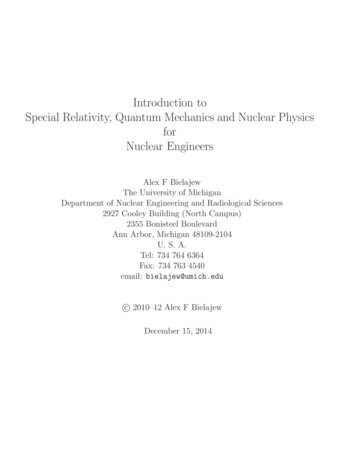
SeventhEditionVector Mechanics for Engineers: DynamicsSample Problem 17.1SOLUTION: Consider the system of theflywheel and block. The workdone by the internal forces exertedby the cable cancels. Note that the velocity of the blockand the angular velocity of thedrum and flywheel are related byv rωFor the drum and flywheel, I 10.5 lb ft s 2 .The bearing friction is equivalent to acouple of 60 lb ft. At the instant shown,the block is moving downward at 6 ft/s. Apply the principle of work andkinetic energy to develop anexpression for the final velocity.Determine the velocity of the block after ithas moved 4 ft downward. 2003 The McGraw-Hill Companies, Inc. All rights reserved.17 - 11SeventhEditionVector Mechanics for Engineers: DynamicsSample Problem 17.1SOLUTION: Consider the system of the flywheel and block. The workdone by the internal forces exerted by the cable cancels. Note that the velocity of the block and the angular velocity ofthe drum and flywheel are related byvvv6 ft sv rωω1 1 4.80 rad sω2 2 2r 1.25 ftr 1.25 Apply the principle of work and kinetic energy to develop anexpression for the final velocity.T1 12 mv12 12 I ω12 1 240 lb(6 ft s )2 1 (10.5 lb ft s )(4.80 rad s )222 32.2 ft s2 255 ft lbT2 12 mv22 12 I ω 22 21 240 2 1 v v2 10.5 2 7.09v222 32.22 1.25 2003 The McGraw-Hill Companies, Inc. All rights reserved.17 - 126
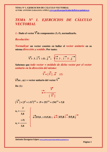
SeventhEditionVector Mechanics for Engineers: DynamicsSample Problem 17.1T1 12 mv12 12 I ω12 255 ft lbT2 12 mv22 12 I ω 22 7.09v22 Note that the block displacement and pulleyrotation are related bys4 ftθ2 2 3.20 radr 1.25 ftThen,U1 2 W (s2 s1 ) M (θ 2 θ1 ) (240 lb )(4 ft ) (60 lb ft )(3.20 rad ) 768 ft lb Principle of work and energy:T1 U1 2 T2255 ft lb 768 ft lb 7.09 v22v2 12.01ft s 2003 The McGraw-Hill Companies, Inc. All rights reserved.v2 12.01ft s17 - 13SeventhEditionVector Mechanics for Engineers: DynamicsSample Problem 17.2SOLUTION: Consider a system consisting of the twogears. Noting that the gear rotationalspeeds are related, evaluate the finalkinetic energy of the system. Apply the principle of work and energy.Calculate the number of revolutionsm A 10 kg k A 200 mmrequired for the work of the appliedmB 3 kg k B 80 mmmoment to equal the final kinetic energyof the system.The system is at rest when a moment Apply the principle of work and energy toof M 6 N m is applied to gear B.a system consisting of gear A. With theNeglecting friction, a) determine thefinal kinetic energy and number ofnumber of revolutions of gear B before revolutions known, calculate the momentits angular velocity reaches 600 rpm,and tangential force required for theand b) tangential force exerted by gearindicated work.B on gear A. 2003 The McGraw-Hill Companies, Inc. All rights reserved.17 - 147
SeventhEditionVector Mechanics for Engineers: DynamicsSample Problem 17.2SOLUTION: Consider a system consisting of the two gears. Notingthat the gear rotational speeds are related, evaluate thefinal kinetic energy of the system.rev ) 62.8 rad s60 s min0.100rω A ω B B 62.8 25.1rad s0.250rAωB (600 rpm )(2π radI A m Ak A2 (10kg )(0.200m )2 0.400 kg m 2I B mB k B2 (3kg )(0.080m )2 0.0192 kg m 2T2 12 I Aω A2 12 I Bω B2 12 (0.400 )(25.1 )2 12 (0.0192)(62.8)2 163.9 J 2003 The McGraw-Hill Companies, Inc. All rights reserved.17 - 15SeventhEditionVector Mechanics for Engineers: DynamicsSample Problem 17.2 Apply the principle of work and energy. Calculatethe number of revolutions required for the work.T1 U1 2 T20 (6θ B )J 163.9Jθ B 27.32 radθB 27.32 4.35 rev2π Apply the principle of work and energy to a systemconsisting of gear A. Calculate the moment andtangential force required for the indicated work.0.100rθ A θ B B 27.32 10.93 rad0.250rAT2 12 I Aω A2 12 (0.400 )(25.1 )2 126.0 JT1 U1 2 T20 M A (10.93 rad ) 126.0JM A rA F 11.52 N m 2003 The McGraw-Hill Companies, Inc. All rights reserved.F 11.52 46.2 N0.25017 - 168
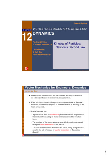
SeventhEditionVector Mechanics for Engineers: DynamicsSample Problem 17.3SOLUTION: The work done by the weight of thebodies is the same. From the principleof work and energy, it follows that eachbody will have the same kinetic energyafter the change of elevation.A sphere, cylinder, and hoop, eachhaving the same mass and radius, arereleased from rest on an incline.Determine the velocity of each bodyafter it has rolled through a distancecorresponding to a change of elevation h. Because each of the bodies has adifferent centroidal moment of inertia,the distribution of the total kineticenergy between the linear and rotationalcomponents will be different as well. 2003 The McGraw-Hill Companies, Inc. All rights reserved.17 - 17SeventhEditionVector Mechanics for Engineers: DynamicsSample Problem 17.3SOLUTION: The work done by the weight of the bodies is thesame. From the principle of work and energy, itfollows that each body will have the same kineticenergy after the change of elevation.vWith ω r v T2 12 mv 2 12 I ω 2 12 mv 2 12 I r I 12 m 2 v 2r 2T1 U1 2 T2I 0 Wh 12 m 2 v 2 r 2Wh2 gh2v m I r 2 1 I mr 2 2003 The McGraw-Hill Companies, Inc. All rights reserved.17 - 189
SeventhEditionVector Mechanics for Engineers: DynamicsSample Problem 17.3 Because each of the bodies has a differentcentroidal moment of inertia, the distribution of thetotal kinetic energy between the linear androtational components will be different as well.2 ghv2 1 I mr 2Sphere :I 52 mr 2v 0.845 2 ghCylinder : I 12 mr 2v 0.816 2 ghHoop :v 0.707 2 ghI mr 2NOTE: For a frictionless block sliding through the samedistance, ω 0, v 2 gh The velocity of the body is independent of its massand radius. The velocity of the body does depend onk2I2 r2mr 2003 The McGraw-Hill Companies, Inc. All rights reserved.17 - 19SeventhEditionVector Mechanics for Engineers: DynamicsSample Problem 17.4SOLUTION: The weight and spring forces areconservative. The principle of work andenergy can be expressed asT1 V1 T2 V2A 30-lb slender rod pivots about thepoint O. The other end is pressedagainst a spring (k 1800 lb/in) untilthe spring is compressed one inch andthe rod is in a horizontal position. Evaluate the initial and final potentialenergy. Express the final kinetic energy in termsof the final angular velocity of the rod. Based on the free-body-diagramequation, solve for the reactions at thepivot.If the rod is released from this position,determine its angular velocity and thereaction at the pivot as the rod passesthrough a vertical position. 2003 The McGraw-Hill Companies, Inc. All rights reserved.17 - 2010
SeventhEditionVector Mechanics for Engineers: DynamicsSample Problem 17.4SOLUTION: The weight and spring forces are conservative. Theprinciple of work and energy can be expressed asT1 V1 T2 V2 Evaluate the initial and final potential energy.V1 Vg Ve 0 12 kx12 12 (1800 lb in.)(1in.)2 900 in lb 75 ft lbV2 Vg Ve Wh 0 (30 lb )(1.5 ft )1 ml 2I 121 30 lb (5 ft )2 12 32.2 ft s 2 45 ft lb Express the final kinetic energy in terms of the angularvelocity of the rod.T2 12 mv22 12 I ω 22 12 m(rω 2 )2 12 I ω 22 1.941lb ft s 2 1 30(1.5ω 2 )2 12 (1.941)ω 22 2.019ω 222 32.2 2003 The McGraw-Hill Companies, Inc. All rights reserved.17 - 21SeventhEditionVector Mechanics for Engineers: DynamicsSample Problem 17.4From the principle of work and energy,T1 V1 T2 V2ω 2 3.86 rad s0 75 ft lb 2.019ω 22 45 ft lb Based on the free-body-diagram equation, solve for thereactions at the pivot.ran 22.3 ft s 2an r ω 22 (1.5 ft )(3.86 rad s )2 22.3 ft s 2rat rαat rα M O (M O )eff Fx (Fx )eff Fy (Fy )eff0 I α m(r α )rα 0Rx m(r α )Rx 0R y 30 lb man(30 lb22.3 ft s 232.2 ft s 2R y 9.22 lbrR 9.22 2003 The McGraw-Hill Companies, Inc. All rights reserved.)17 - 2211
SeventhEditionVector Mechanics for Engineers: DynamicsSample Problem 17.5SOLUTION: Consider a system consisting of the tworods. With the conservative weight force,T1 V1 T2 V2 Evaluate the initial and final potentialenergy.Each of the two slender rods has amass of 6 kg. The system is releasedfrom rest with β 60o.Determine a) the angular velocity ofrod AB when β 20o, and b) thevelocity of the point D at the sameinstant. Express the final kinetic energy of thesystem in terms of the angular velocities ofthe rods. Solve the energy equation for the angularvelocity, then evaluate the velocity of thepoint D. 2003 The McGraw-Hill Companies, Inc. All rights reserved.17 - 23SeventhEditionVector Mechanics for Engineers: DynamicsSample Problem 17.5SOLUTION: Consider a system consisting of the two rods. Withthe conservative weight force,T1 V1 T2 V2 Evaluate the initial and final potential energy.V1 2Wy1 2(58.86 N )(0.325 m ) 38.26 JV2 2Wy2 2(58.86 N )(0.1283 m ) 15.10 J(W mg (6 kg ) 9.81m s 2 58.86 N) 2003 The McGraw-Hill Companies, Inc. All rights reserved.17 - 2412
SeventhEditionVector Mechanics for Engineers: DynamicsSample Problem 17.5 Express the final kinetic energy of the system in termsof the angular velocities of the rods.rv AB (0.375 m )ωrrSince vB is perpendicular to AB and vD is horizontal,the instantaneous center of rotation for rod BD is C.CD 2(0.75 m )sin 20 0.513 mBC 0.75 mand applying the law of cosines to CDE, EC 0.522 mConsider the velocity of point BrvB ( AB )ω ( BC )ω ABω BD ωrvBD (0.522 m )ωFor the final kinetic energy,1 ml 2 1 (6 kg )(0.75 m )2 0.281kg m 2I AB I BD 12121 mv 2 1 I ω 2 1 mv 2 1 I ω 2T2 12AB 2 AB AB 12BD 2 BD BD1 (6 )(0.375ω )2 1 (0.281)ω 2 1 (6 )(0.522ω )2 1 (0.281)ω 2 122122 1.520ω 2 2003 The McGraw-Hill Companies, Inc. All rights reserved.17 - 25SeventhEditionVector Mechanics for Engineers: DynamicsSample Problem 17.5 Solve the energy equation for the angular velocity,then evaluate the velocity of the point D.T1 V1 T2 V20 38.26 J 1.520ω 2 15.10 Jω 3.90 rad srω AB 3.90 rad svD (CD )ω (0.513 m )(3.90 rad s ) 2.00 m srvD 2.00 m s 2003 The McGraw-Hill Companies, Inc. All rights reserved.17 - 2613
SeventhEditionVector Mechanics for Engineers: DynamicsPrinciple of Impulse and Momentum Method of impulse and momentum:- well suited to the solution of problems involving time and velocity- the only practicable method for problems involving impulsivemotion and impact.Sys Momenta1 Sys Ext Imp1-2 Sys Momenta2 2003 The McGraw-Hill Companies, Inc. All rights reserved.17 - 27SeventhEditionVector Mechanics for Engineers: DynamicsPrinciple of Impulse and Momentum The momenta of the particles of a system may be reduced to a vectorattached to the mass center equal to their sum,rrrL vi mi mvand a couple equal to the sum of their moments about the mass center,rr rH G ri′ vi mi For the plane motion of a rigid slab or of a rigid body symmetrical withrespect to the reference plane,rH G Iω 2003 The McGraw-Hill Companies, Inc. All rights reserved.17 - 2814
SeventhEditionVector Mechanics for Engineers: DynamicsPrinciple of Impulse and Momentum Principle of impulse and momentum for the plane motion of a rigid slabor of a rigid body symmetrical with respect to the reference planeexpressed as a free-body-diagram equation, Leads to three equations of motion:- summing and equating momenta and impulses in the x and ydirections- summing and equating the moments of the momenta and impulseswith respect to any given point 2003 The McGraw-Hill Companies, Inc. All rights reserved.17 - 29SeventhEditionVector Mechanics for Engineers: DynamicsPrinciple of Impulse and Momentum Noncentroidal rotation:- The angular momentum about OI Oω I ω (mv )r I ω (mr ω )r() I mr 2 ω- Equating the moments of the momenta andimpulses about O,t2I Oω1 M O dt I Oω 2t1 2003 The McGraw-Hill Companies, Inc. All rights reserved.17 - 3015
SeventhEditionVector Mechanics for Engineers: DynamicsSystems of Rigid Bodies Motion of several rigid bodies can be analyzed by applyingthe principle of impulse and momentum to each bodyseparately. For problems involving no more than three unknowns, it maybe convenient to apply the principle of impulse andmomentum to the system as a whole. For each moving part of the system, the diagrams of momentashould include a momentum vector and/or a momentum couple. Internal forces occur in equal and opposite pairs of vectors anddo not generate nonzero net impulses. 2003 The McGraw-Hill Companies, Inc. All rights reserved.17 - 31SeventhEditionVector Mechanics for Engineers: DynamicsConservation of Angular Momentum When no external force acts on a rigid body or a system of rigidbodies, the system of momenta at t1 is equipollent to the systemat t2. The total linear momentum and angular momentum aboutany point are conserved,rr( H 0 )1 (H 0 )2L1 L2 When the sum of the angular impulses pass through O, thelinear momentum may not be conserved, yet the angularmomentum about O is conserved,( H 0 )1 (H 0 )2 Two additional equations may be written by summing x andy components of momenta and may be used to determinetwo unknown linear impulses, such as the impulses of thereaction components at a fixed point. 2003 The McGraw-Hill Companies, Inc. All rights reserved.17 - 3216
SeventhEditionVector Mechanics for Engineers: DynamicsSample Problem 17.7SOLUTION: Apply principle of impulse and momentumto find variation of linear and angularvelocities with time.Uniform sphere of mass m andradius r is projected along a roughhorizontal surface with a linearvelocity v1 and no angular velocity.The coefficient of kinetic friction isµk .Determine a) the time t2 at whichthe sphere will start rolling withoutsliding and b) the linear and angularvelocities of the sphere at time t2. Relate the linear and angular velocitieswhen the sphere stops sliding by notingthat the velocity of the point of contact iszero at that instant. Substitute for the linear and angularvelocities and solve for the time at whichsliding stops. Evaluate the linear and angular velocitiesat that instant. 2003 The McGraw-Hill Companies, Inc. All rights reserved.17 - 33SeventhEditionVector Mechanics for Engineers: DynamicsSample Problem 17.7SOLUTION: Apply principle of impulse and momentumto find variation of linear and angularvelocities with time. Relate linear and angular velocities whensphere stops sliding by noting that velocitySys Momenta1 Sys Ext Imp1-2 Sys Momenta2 of point of contact is zero at that instant.y components:Nt Wt 0N W mgx components:mv1 Ft mv2mv1 µ k mgt mv2v2 rω 2v2 v1 µ k gtmoments about G:Ftr I ω 2(µ k mg )tr (52 mr 2 )ω 2 Substitute for the linear and angularvelocities and solve for the time at whichsliding stops. 5 µk g v1 µ k gt r t 2 r t ω2 5 µk gt2 r 2003 The McGraw-Hill Companies, Inc. All rights reserved.2 v17 µk g17 - 3417
SeventhEditionVector Mechanics for Engineers: DynamicsSample Problem 17.7 Evaluate the linear and angular velocitiesat that instant. 2 v1 v2 v1 µ k g 7 µk g 5v2 v17Sys Momenta1 Sys Ext Imp1-2 Sys Momenta2y components:N W mgx components:v2 v1 µ k gtmoments about G:ω2 ω2 5 µ k g 2 v1 2 r 7 µ k g ω2 5 µk gt2 r5 v17rv2 rω 2 5 µk g v1 µ k gt r t 2 r t 2 v17 µk g 2003 The McGraw-Hill Companies, Inc. All rights reserved.17 - 35SeventhEditionVector Mechanics for Engineers: DynamicsSample Problem 17.8SOLUTION: Observing that none of the externalforces produce a moment about the yaxis, the angular momentum isconserved.Two solid spheres (radius 3 in.,W 2 lb) are mounted on a spinninghorizontal rod ( I R 0.25 lb ft s 2 ,ω 6 rad/sec) as shown. The balls areheld together by a string which issuddenly cut. Determine a) angularvelocity of the rod after the balls havemoved to A’ and B’, and b) the energylost due to the plastic impact of thespheres and stops. Equate the initial and final angularmomenta. Solve for the final angularvelocity. The energy lost due to the plastic impactis equal to the change in kinetic energyof the system. 2003 The McGraw-Hill Companies, Inc. All rights reserved.17 - 3618
SeventhEditionVector Mechanics for Engineers: DynamicsSample Problem 17.8Sys Momenta1 Sys Ext Imp1-2 Sys Momenta2SOLUTION: Observing that none of theexternal forces produce amoment about the y axis, theangular momentum isconserved. Equate the initial and finalangular momenta. Solve forthe final angular velocity.2[(ms r1ω1 )r1 I S ω1 ] I Rω1 2[(ms r2ω 2 )r2 I S ω 2 ] I Rω 2ω 2 ω1ms r12 I S I Rms r22 I S I Rω1 6 rad sI R 0.25 lb ft s 2 2 lb 2 2 ft 0.00155 lb ft s 2I S 52 ma 2 25 2 12 32.2fts 22 2 5 2 2 25 mS r12 0.0108 mS r2 0.2696 32.2 12 32.2 12 2003 The McGraw-Hill Companies, Inc. All rights reserved.ω 2 2.08 rad s17 - 37SeventhEditionVector Mechanics for Engineers: DynamicsSample Problem 17.8 The energy lost due to theplastic impact is equal to thechange in kinetic energy of thesystem.ω1 6 rad sI R 0.25 lb ft sω 2 2.08 rad s2I S 0.00155 lb ft s 2mS r12 0.0108 lb ft s 2(mS r22 0.2696 lb ft s 2)()T 2 12 mS v 2 12 I S ω 2 12 I Rω 2 12 2mS r 2 2 I S I R ω 2T1 12 (0.275)(6 )2 4.95 ft lbT2 12 (0.792 )(2.08)2 1.71ft lb T T2 T1 1.71 4.95 T 3.24 ft lb 2003 The McGraw-Hill Companies, Inc. All rights reserved.17 - 3819
SeventhEditionVector Mechanics for Engineers: DynamicsSample Problem 17.9SOLUTION: Consider a system consisting of thebullet and panel. Apply the principle ofimpulse and momentum. The final angular velocity is foundfrom the moments of the momenta andimpulses about A.A 0.05-lb bullet is fired into the side of a20-lb square panel which is initially atrest. The reaction at A is found from thehorizontal and vertical momenta andimpulses.Determine a) the angular velocity of thepanel immediately after the bulletbecomes embedded and b) the impulsivereaction at A, assuming that the bulletbecomes embedded in 0.0006 s. 2003 The McGraw-Hill Companies, Inc. All rights reserved.17 - 39SeventhEditionVector Mechanics for Engineers: DynamicsSample Problem 17.9SOLUTION: Consider a system consistingof the bullet and panel. Applythe principle of impulse andmomentum. The final angular velocity isfound from the moments ofthe momenta and impulsesabout A.moments about A:mB v Bv2 (1412 ft ) 0 m P v2 (129 ft ) I Pω22(129 ft )ω21 20 18 2I P 16 mPb 2 0.2329 lb ft s6 32.2 12 ( )( 0.05 20 9 ω2 (1500 ) 1412 32.2 32.2 12ω 2 4.67 rad sv2 ( )ω2 3.50 ft s)(129 ) 0.2329ω2ω 2 4.67 rad s912 2003 The McGraw-Hill Companies, Inc. All rights reserved.17 - 4020
SeventhEditionVector Mechanics for Engineers: DynamicsSample Problem 17.9 The reactions at A are foundfrom the horizontal andvertical momenta andimpulses.ω 2 4.67 rad sv2 (129 )ω2 3.50 ft sx components:mB vB Ax t m p v2 20 0.05 (3.50 ) (1500 ) Ax (0.0006 ) 32.2 32.2 Ax 259 lbAx 259 lby components:0 Ay t 0Ay 0 2003 The McGraw-Hill Companies, Inc. All rights reserved.17 - 41SeventhEditionVector Mechanics for Engineers: DynamicsSample Problem 17.11SOLUTION: Apply the principle of impulse andmomentum to relate the velocity of thepackage on conveyor belt A before theimpact at B to the angular velocity aboutB after impact.A square package of mass m movesdown conveyor belt A with constantvelocity. At the end of the conveyor,the corner of the package strikes a rigidsupport at B. The impact is perfectlyplastic.Derive an expression for the minimumvelocity of conveyor belt A for whichthe package will rotate about B andreach conveyor belt C. Apply the principle of conservation ofenergy to determine the minimum initialangular velocity such that the masscenter of the package will reach aposition directly above B. Relate the required angular velocity tothe velocity of conveyor belt A. 2003 The McGraw-Hill Companies, Inc. All rights reserved.17 - 4221
SeventhEditionVector Mechanics for Engineers: DynamicsSample Problem 17.11SOLUTION: Apply the principle of impulse and momentum to relate the velocity of the package onconveyor belt A before the impact at B to angular velocity about B after impact.Moments about B:(mv1 )(12 a ) 0 (mv2 )( 22 a ) Iω 2v2 (mv1 )(12 a ) 0 m( 22 aω 2 )( 22 a ) (16 ma 2 )ω 2( a )ω222I 16 m a 2v1 43 aω 2 2003 The McGraw-Hill Companies, Inc. All rights reserved.17 - 43SeventhEditionVector Mechanics for Engineers: DynamicsSample Problem 17.11 Apply the principle of conservation of energy to determinethe minimum initial angular velocity such that the masscenter of the package will reach a position directly above B.T2 V2 T3 V3T2 12 mv22 12 I ω 22h2 (GB )sin (45 15 ) ( a )sin 60 0.612a22 12 m(2aω 22) ( ma )ω21 12 6222 13 ma 2ω 22V2 Wh2T3 0(solving for the minimum ω2)V3 Wh31 ma 2ω 223ω 22 h3 2a2 0.707 a Wh2 0 Wh33Wma 2(h3 h2 ) 3g2 (0.707a 0.612a ) av1 43 aω 2 43 a 0.285 g a 2003 The McGraw-Hill Companies, Inc. All rights reserved.0.285 g av1 0.712 ga17 - 4422
Seventh Vector Mechanics for Engineers: Dynamics Edition 17 - 3 Introduction Method of work and energy and the method of impulse and momentum will be used to analyze the plane motion of rigid bodies and systems of rigid bodies. Principle of work and energy is well suited to the solution of problems involving displacements and velocities.