Transcription
Northumbria Research LinkCitation: Han, Lei, Cheng, Xuefeng, Jiang, Lei, Li, Rong, Ding, Guofu and Qin, Sheng-feng(2019) Research on parametric modeling and grinding methods of bottom edge of toroidshaped end-milling cutter. Proceedings of the Institution of Mechanical Engineers, Part B:Journal of Engineering Manufacture, 233 (1). pp. 31-43. ISSN 0954-4054Published by: SAGEURL:https://doi.org/10.1177/0954405417717547 https://doi.org/10.1177/0954405417717547 thumbria University has developed Northumbria Research Link (NRL) to enable usersto access the University’s research output. Copyright and moral rights for items onNRL are retained by the individual author(s) and/or other copyright owners. Single copiesof full items can be reproduced, displayed or performed, and given to third parties in anyformat or medium for personal research or study, educational, or not-for-profit purposeswithout prior permission or charge, provided the authors, title and full bibliographicdetails are given, as well as a hyperlink and/or URL to the original metadata page. Thecontent must not be changed in any way. Full items must not be sold commercially in anyformat or medium without formal permission of the copyright holder. The full policy isavailable online: http://nrl.northumbria.ac.uk/policies.htmlThis document may differ from the final, published version of the research and has beenmade available online in accordance with publisher policies. To read and/or cite from thepublished version of the research, please visit the publisher’s website (a subscriptionmay be required.)
Research on parametric modeling and grinding methodsof bottom edge of toroid-shaped end milling cutterLei Han1, Xuefeng Cheng1, Lei Jiang1, Rong Li1, Guofu Ding1, Shengfeng Qin21Institute of Advanced Design and Manufacturing, School of Mechanical Engineering,Southwest Jiaotong University, Chengdu, China2School of Design, Northumbria University, Newcastle upon Tyne, UKCorresponding author:Guofu Ding, Institute of Advanced Design and Manufacturing, School of MechanicalEngineering, Southwest Jiaotong University, Chengdu, 610031, ChinaEmail: dingguofu@163.comAbstractFor a toroid-shaped end milling cutter to have multi-structure features of tooth offsetcenter and introversion of bottom edge, this paper proposes a generalized parametricmodeling method of the bottom edge, including a straight edge segment and a circulararc edge segment. And based on the parametric model this paper also deduces thecorresponding tool path for grinding of the bottom edge’s rake and flank faces. Theparametric modeling method is based on the geometric analytic equations while thegrinding method is driven by the proposed parametric model and the parameters ofrake and flank faces. The two methods can be applied to a bottom edge of a cutterwith multi-structure features to guarantee G1 continuity at the two joints forconnecting a circular arc edge with a straight edge and a conical helix edgerespectively. In order to verify the accuracy of proposed methods, experiments werecarried out. The modeling and grinding experimental results verified the accuracy andutility of the methods.Key words
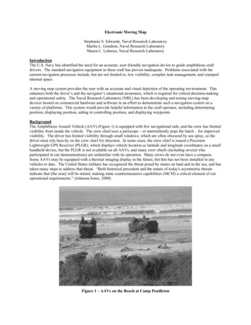
Toroid-shaped end milling cutter; bottom edge; parametric modeling method;grinding method; integrated tool design and manufacturing1 IntroductionToroid-shaped end milling cutter (TEMC) is widely used in manufacturing ofcomplicated parts with free-form surfaces[1]. The main parts of cutting edgesparticipated in milling are a straight edge, a circular arc edge and a conical helix edgeshown in Fig. 1. TEMC has the advantages of high adaptability and machiningefficiency compared with ball-end milling cutter under constant scallop-heightcutting[2]. And it has the ability to produce the periphery of parts meeting with thebottom floor with fillets[3]. Also, this type of cutter has higher material removal rateand lower flank wear rate because bottom edge is more solid[4][5] and thus, themachining quality is much more stable[6] compared with flat-end milling cutter.Generally, the straight edge on TEMC having a tooth offset to the bottom centercan improve its strength, and introversion to reduce friction between bottom edge andmachined surface. As shown in Fig. 1, h is the tooth offset distance and η is the dishangle. Meanwhile TEMC has smooth cutting edges to ensure the cutting continuityduring machining. However, the multi-structure features lead to difficulties inparametric modeling and grinding. Although there is a complete set of theory that canbe used to design and manufacture TEMC without multi-structure features at present,it cannot be applied directly to TEMC with multi-structure features. Therefore theresearch on parametric modeling and grinding methods of this kind of TEMC is ofgreat significance.
Fig. 1Main parts of cutting edges (Straight edge has multi-structure features)Precise parametric modeling of a bottom edge which determines the structure ofend milling cutter is an essential for grinding of TEMC. Furthermore, the edge curveis also the guideline of the grinding wheel movement during grinding. Thereforeparametric modeling of a bottom edge must be studied first. Many scholars have donemuch research about it. Chen adopted a supplementary cutting edge with a constantpitch to supply a general reference for TEMC with a constant angle between thecutting edge and the cutter axis[6]. Chen presented a precise mathematical modelingprocedure for the design of cutters with a circular arc edge, the cutting edge forms aconstant angle with the longitude curve[7], and presented a systematically designmodel of the involute end-milling cutter which cutting edge curves forms a constantangle with the cutter axis[8]. Chen presented a design model of TEMC, the cuttingedge forms an approximately constant angle with the cutter axis[9]. Lin proposed ageometrical model of the cutting edge on TEMC with a constant angle between thecutting edge and the cutter axis[10]. Hsieh derived a mathematical model of the idealconical helix edge which formed a constant angle to the longitudinal line at the toroidsurface[11]. Tang studied the design models of the cutting edge with the convex curvegeneratrix, and put forward three mathematical models, i.e., planar cutting edges,helical cutting edges with a constant angle to the meridian and helical cutting edgeswith a constant pitch to avoid the problem of the inexistence of the cutting edge in thearea near the end face of a cutter and the cutting edges are smoothly connected[12][13].Yang introduced the design of a cutting edge with equal pitch, and the edge wascontinuous at the joint of the circular torus and the cylindrical surface[14]. Han gavethe design method of the cutting edge which was defined as an approximate equal
pitch curve with a concave arc as generator[15]. Lv established a mathematic modelusing infinitesimal geometry for the cutting edge design which used equal leadhelix[16][17]. Although references [1], [18] and [19] used the generalized mathematicalmodel proposed by Engin and Altintas[3][20][21], and seven geometric parameters weredefined, if the circular torus is not a full quarter, there will be a discontinuity on thebottom edge. Cheng used the orthogonal helix edge curve as the S-shaped edge curveof ball-end milling cutter, the edge curve acquired based on the mathematical modelproposed has a good S-shape and can connect with the circumferential edge curvesmoothly. Furthermore, the model can be used easily to establish the S-shaped edgecurve with tooth offset center or without tooth offset center[22].Until now, several kinds of curves are used as a bottom edge on TEMC, such asan equal pitch edge curve, an equal helix angle edge curve with the longitude line, anequal helix angle edge curve with the cutter axis, a planar edge curve and anorthogonal helix edge curve. They have good edge curve shapes and can be used inseries types of TEMC. However, present modeling methods using these kinds ofcurves are not concerned with a straight edge, not to mention the straight edge withmulti-structure features, thus leading to complexity and difficulty of the grindingmethod. The grinding methods of TEMC are also studied by many scholars. Liuproposed a grinding process of the rake and flank faces and calculated the tool pathand direction vector of grinding wheel[4]. Chen obtained the sectional profile of thegrinding wheel by using an inverse problem-solving technique and the manufacturingmodel presented can be used on a two-axis NC machine[7]. Lin provided grindingmodels of a section design, feeding speeds and relative position of the grindingwheel[10]. Hsieh developed a systematic method for the grinding of the helical fluteand the cutting edge, and considered the section profile and relative feeding velocitiesof the grinding wheel[11]. Bao studied a virtual two-axis grinding model of TEMCwith an equal helix lead cutting edge and an equal helix angle cutting edgerespectively[23].In the above studies, many scholars focused on the parametric modeling andgrinding methods of TEMC without multi-structure features of tooth offset to the
center and introversion of the bottom edge. And thus the existing research results arejust in a limited scope of application of the methods presented and no unified model isformed. In order to meet the requirements of the design and manufacturing of atoroid-shaped end milling cutter especially its bottom edge has multi-structurefeatures, this article presents a generalized parametric modeling method of a bottomedge, and based on this, a grinding method for the rake and flank faces of the bottomedge can make the cutting edges with G1 continuity, that is (1) the cutting edge curvesmeet at the joint points and (2) their tangent directions at the joints are the same. TheG1 continuity makes the composite cutting edge smooth. The modeling and grindingexperiments indicates that the proposed cutter modelling and grinding methods canshorten the production cycle and improve the success rate of the design of atoroid-shaped end milling cutter, thus reduce the cost of cutter production.Furthermore, the proposed general and parametric modelling of a TEMC has a greatpotential to support optimal cutter design for different machining applications and thecorresponding grinding method can easily realize the cutter design into toolmanufacturing. This provides an integrated cutting design and manufacturing solutionfor wider applications.This article is organized as follows: Section 2 describes the mathematical modelof a bottom edge with multi-structure features of tooth offset center and introversion.Section 3 presents a grinding method of a bottom edge based on its 3D mathematicalmodel. The experiments and results are described in section 4, and finally conclusionsare drawn in section 5.2 Parametric modeling method of bottom edgeAmong many kinds of curves mentioned above, the planar edge curve has a goodcurve shape and more simple mathematical computation compared with others. Thistype of edge curve can reach G1 continuity at the two joints of a circular arc edge witha straight edge and a conical helix edge respectively, and the straight edge can have
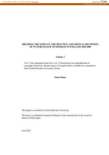
multi-structure features whether or not. So planar edge curve is adopted, i.e., thecircular arc edge is the intersecting planar curve of the circular torus and the planecomposed of an extended line of straight edge and a tangential line at the end of theconical helix edge.As shown in Fig. 2, the revolving surfaces of the cutting edges on TEMC aredefined as three parts: a circular truncated conical surface A where the conical helixedge a lies, a circular torus B where the circular arc edge b lies, and a concave conicalsurface C. Their relationship is that B is tangent with A and C. Straight edge c has themulti-structure features of tooth offset center and introversion.Define I as the intersection of a and b, J as the intersection of b and c. Define L1as the extended line of c, L2 as the tangential line of a at I, L3 as the intersecting lineof B and C, L4 as the intersecting line of A and B. Define P as the intersection of L1and L2. Plane M is composed of L1 and L2. The bottom edge consists of b and c.Fig. 2Relevant geometrical elements of bottom edge2.1 Parametric model of edge cTo reduce the complexity of mathematical modeling, define the coordinatesystem [O1-X1Y1Z1] as the first coordinate system, and the origin O1 as center of B. Z1is the cutter axis and the positive direction is from the cutter shank to the tip. X1 isparallel to the projection of c on the plane X1Y1. The point coordinates in the firstcoordinate system are identified by subscript 1.
Let γ be the angle between X1-axis and the projection of IO1 on the plane X1Y1.Rotate the first coordinate system on Z1-axis by angle γ negatively, and the coordinatesystem [O2-X2Y2Z2] is obtained as the second coordinate system. The pointcoordinates in the second coordinate system are identified by subscript 2. Then, theparametric models of c and b can be described in the second coordinate system.As shown in Fig. 3, define L as the intersection of L3 and the plane X1Z1, Q as thetip of C, K as the endpoint of c, Or as the center of the cross section of B on the planeX1Z1. Let re be the section radius of B, R be the distance between I and the cutter axis,κ be the half cone angle of A, β be the helix angle of a at I (angle between the helixedge on the revolving surface and the generator curve).Fig. 3Schematic diagram for the design of edge cOn the basis of cutter geometry relationship, the coordinates of J and K in thefirst coordinate system are as follows x J 1 J 1 y J 1 z J 1 xK 1 K 1 y K 1 z K 1 (x r cosη eOr 12 re sin η ) h 2 ,h re cosη . 22( xOr 1 re sinη ) h tanη 0h(1)(2)According to the direction of the coordinate system, the rotation transformationmatrix from the first coordinate system to the second coordinate system can be
expressed as follows cos γT1 2 sin γ 0sin γcos γ00 0 . 1 (3)Obviously, the coordinates of I can be described as xI 2 I 2 y I 2 z I 2 R 0 , re sin κ (4)where: R xOr 1 re cos κ .Let τL1 2, τL2 2 be the unit direction vector of L1 and L2 respectively. Then τL1 2and the parametric equation L1 2(t1) of L1 can be obtained by Eqs. (5) and (6)respectivelyτ L1 2 τ L1 x 2 cos γ cosη sin γ cosη , τ L1 y 2 τ L1z 2 sin η x xJ 2 t1 τ L1x 2 , L1 2 ( t1 ) y y J 2 t1 τ L1 y 2 , z z t τJ 2L1 z 2 .1 (5)(6)where t1 is the independent variable.Similarly, τL2 2 and the parametric equation L2 2(t2) of L2 can be obtained by Eqs.(7) and (8) respectively τ L 2 x 2 τ L 2 2 τ L2 y 2 τ L 2 z 2 cos β sin κ ,sin β cos β cos κ x xI 2 t2 τ L 2 x 2 , L2 2 ( t2 ) y yI 2 t2 τ L 2 y 2 , z z t τI 22L2z 2. where t2 is the independent variable.For L1 and L2 intersect at P, then(7)(8)
xP xJ 2 t1 τ L1x 2 xI 2 t2 τ L 2 x 22 yJ 2 t1 τ L1 y 2 yI 2 t2 τ L 2 y 2 . yP 2 z J 2 t1 τ L1z 2 z I 2 t2 τ L 2 z 22 zP (9)So t1, t2 and γ can be obtained by Eqs. (5) to (9), shown as follows ( yI 2 t2 τ L 2 y 2 )( xJ 1 t1 cosη ) ( xI 2 t2 τ L 2 x 2 ) yJ 1 , sin γ 2yJ2 1 ( xJ 1 t1 cosη ) ( xI 2 t2 τ L 2 x 2 )( xJ 1 t1 cosη ) ( yI 2 t2 τ L 2 y 2 ) yJ 1 , cos γ 2yJ2 1 ( xJ 1 t1 cosη ) where: t1 t2 T1 (10) T2 T22 4T1 T3;2T1z J 1 z I 2 t1 sin ητ L2z 2(τ2L2x 2; τ L22 y 2 ) sin 2 η τ L22 z 2 cos 2 η ; xJ 1 τ L22 z 2 cosη τ L 2 x 2 ( xI 2 τ L 2 z 2 z I 2 τ L 2 x 2 z J 1 τ L 2 x 2 ) ;T2 2 τ L 2 y 2 ( yI 2 τ L 2 z 2 z I 2 τ L 2 y 2 z J 1 τ L 2 y 2 ) sin η T3 (x τ L 2 z 2 z I 2 τ L 2 x 2 z J 1 τ L 2 x 2 ) 2I 2( yI 2 τ L 2 z 2 zI 2 τ L 2 y 2 zJ 1 τ L 2 y 2 ) ( xJ2 1 yJ2 1 )τ L22 z 22.For c and L1 are collinear, the unit direction vector τc 2 and parametric equationc 2(t1) of edge c can be obtained by Eqs. (5) and (6) respectively, and the range of t1 is[0, xJ 2 τ L1 x 2 ].2.2 Parametric model of edge bAs shown in Fig. 4, define E as an arbitrary point on B, E′ as the rotatingprojection of E on the plane X1Z1, N as an arbitrary point on bottom edge. Let θ be theangle between E′Or and X1-axis (counter clockwise direction is positive), φ be theangle between the projection of EO2 on the plane X2Y2 and X2-axis (clockwise
direction is positive).Fig. 4Schematic diagram for the design of edge bThe normal vector nM 2 of M is determined by the vector cross-product of τL1 2and τL2 2 as followsnM 2 nMx 2 sin β sin η cos β cos κ cosη sin γ nMy 2 τ L1 2 τ L 2 2 cos β cos κ cosη cos γ cos β sin κ sin η , nMz 2 cos β sin κ cosη sin γ sin β cosη cos γ (11)Hence, the equation of M can be obtained by Eq. (12)nMx 2 ( x xI 2 ) nMy 2 ( y yI 2 ) nMz 2 ( z z I 2 ) 0.(12)By the definition of the circular torus[26], the parametric equation of B can bewritten as x ( xOr 1 re cos θ ) cos φ , π B 2 (θ , φ ) y ( xOr 1 re cos θ ) sin φ , κ θ η , 0 φ 2π .2 θzrsin, e(13)Since b is defined as a planar curve, then b is the intersecting line of M and B andangle φ can be determined by Eqs. (12) and (13)22 22 sin φ nMy 2 (T4 nMz 2 re sin θ ) nMx 2 ( nMx 2 nMy 2 ) ( xOr 1 re cos θ ) (T4 nMz 2 re sin θ ) , ( nMx2 2 nMy2 2 ) ( xOr 1 re cos θ ) 2222 nMx 2 (T4 nMz 2 re sin θ ) nMy 2 ( nMx2 nMy 2 ) ( xOr 1 re cos θ ) ( T4 nMz 2 re sin θ ) cos φ , ( nMx2 2 nMy2 2 ) ( xOr 1 re cos θ ) (14)
where:T4 xI 2 nMx 2 yI 2 nMy 2 z I 2 nMz 2 .Substituting Eq. (14) into Eq. (13) gives the parametric equation b 2(θ) of edge b nMx 2 (T4 nMz 2 re sin θ ) nMy 2 x nMy 2 (T4 nMz 2 re sin θ ) nMx 2 ) b 2 (θ y z re sin θ , (n2Mx 2(n2 nMy2 ) ( xOr 1 re cos θ ) ( T4 nMz 2 re sin θ )22Mx 2(n2Mx 2(n22 nMy2 ) ( xOr 1 re cos θ ) ( T4 nMz 2 re sin θ )2Mx 2,2 nMy2 )2 n2My 2)2π , κ θ η .2 (15)Take the derivative of Eq. (15) with respect to θ, the unit direction vector τb 2(θ)of edge b can be expressed as 22 nMy 2 T6 T7 sin θ nMy 2 nMz 2 T5 cos θ nMx 2 nMz 2 T6 T7 T5 cos θ 2T6 T6 T7 2 T5 2 (T5 sin θ T7 nMz 2 cos θ ) τ bx 2 22π nMx 2 T6 T7 sin θ nMx 2 nMz 2 T5 cos θ nMy 2 nMz 2 T6 T7 T5 cos θ τ b τby 2 , κ θ η ,2 (θ ) 2222 T6 T6 T7 T5 (T5 sin θ T7 nMz 2 cos θ ) τ bz 2 T6 T7 2 T5 2 cos θ 222 T6 T7 T5 (T5 sin θ T7 nMz 2 cos θ ) (16)where: T5 T4 nMz 2 re sin θ ;22 T6 nMx2 nMy 2 ;T xOr 2 re cos θ .72.3 The generalized helix angle of edge bThe parametric model of edge b is already obtained. Although edge b is a planaredge curve, it can be also regarded as a curve with a variable helix angle. At present,the generalized helix angle on the revolving surface has two definitions[24]: one is theangle between the helix edge on the revolving surface and the generator curve[22], theother is the angle between the helix edge on the revolving surface and the cutteraxis[25]. The first definition is considered in this paper. The unit tangent vector of thegenerator curve of B at E can be expressed in the following form
sin θ cos φ τ BE 2 (θ ) sin θ sin φ cos θ (17)Hence the generalized helix angle at N can be given byβ r arccosarccosτ BE 2 (θ ) τ b 2 (θ )τ BE 2 (θ ) τ b 2 (θ )T6 T7 2 T5 2T6 T7 2 T5 2 (T5 sin θ T7 nMz 2 cos θ )2π , κ θ η .2 (18)2.4 Parametric model of edge aAs shown in Fig. 5, define F as an arbitrary point on a. Let ϕ be the anglebetween the projection of FO2 on the plane X2Y2 and X2-axis (clockwise direction ispositive).Fig. 5Schematic diagram for the design of edge aBy the definition of the generalized helix, the parametric equation a 2(ϕ) of edgea can be written as
x xI 2 e ϕ sin( κ ) cot β cos ϕ , ϕ sin( κ ) cot β sin ϕ ,a 2 (ϕ ) y xI 2 e x 1 e ϕ sin( κ ) cot β z I 2 re sin κ , tan( κ ) (ϕ 0) .(19)Take the derivative of Eq. (19) with respect to ϕ, the unit direction vector τa 2(ϕ)of edge a can be expressed as T8 x ,2 T8 T92 T102 τ ax 2 T9 τ a 2 (ϕ ) τ a y 2 ,y 222 TTT 8910 τ az 2 T10 z ,222 TTT8910 (ϕ 0) .(20)where: T8 sin κ cot β cos ϕ sin ϕ ;T9 sin κ cot β sin ϕ cos ϕ ;T10 cos κ cot β . 3 Grinding method of bottom edgeParametric model of the bottom edge is the base of the tool path of the grindingwheel. Bottom edge is the intersection curve of rake face and flank face, and itsstructural parameters are guaranteed by the grinding process of the two faces. ForTEMC has a complex structure and lots of parameters and the purpose of the grindingmethod in this paper is to guarantee the precision of parameters related to bottom edge,the detailed method of the section profile formation was not presented here forsimplification purpose. For convenience, the tool path calculation is deduced in thefirst coordinate system thus the origin of programming is O1 and grinding wheel wear
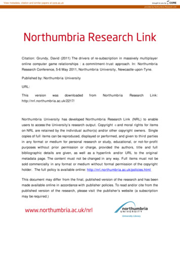
is not considered.3.1 Parameters of the grinding wheelThe profile of V-shaped grinding wheel and Cup-shaped grinding wheel can bothbe defined by three parameters. Let Rg (the radius of the big-end of the grindingwheel), Hg (the thickness of the grinding wheel) and αg (the taper angle of thegrinding wheel) be three given geometric parameters of the grinding wheel profile,shown in Fig. 6.Define the coordinate system [Og-XgYgZg] as the grinding wheel coordinatesystem, and the origin Og as the center of the big-end of the grinding wheel, Zg as thegrinding wheel axis. Let n 1 (the unit direction vector of Zg-axis) and P 1 (thecoordinates of the origin Og) be two parameters of tool path in the first coordinatesystem. Define ν as the inclined angle in grinding process. Let ν be ν′ in rake facegrinding and let ν be ν′′ in flank face grinding.Fig. 6Geometric parameters of the profile of grinding wheel3.2 Grinding tool path for rake faceThe grinding of the rake face of bottom edge is to form the chip-breaker-grooveof the end cutting edge and the normal rake angle of TEMC.Define the coordinate system [On-XnYnZn] as the movable normal-section localcoordinate system, the origin On coincides with N, Zn-axis is tangent to the bottomedge and Xn-axis and the cutter axis lies in the same plane. In the grinding process, ν′(the inclined angle restrained by the depth of chip-breaker-groove in rake facegrinding) and γn (the normal rake angle of bottom edge) are pre-designed.In a rake face grinding process, the coordinate system [O′g-X′gY′gZ′g] can be
obtained from the coordinate system [On-XnYnZn] by the following steps: rotate thecoordinate system [On-XnYnZn] around Zn-axis by angle γn positively, then aroundYn-axis by angle ν′ negatively, around Xn-axis by 90 negatively, at last translate therotated coordinate system from On to O′g to get the grinding wheel coordinate system.Let N 1 [xN 1, yN 1, zN 1]T be the coordinates of N in the first coordinate system.Define T1-n and R1-n as translation and rotation homogeneous transformationmatrix(HTM) from the coordinate system [O1-X1Y1Z1] to [On-XnYnZn] respectively,T′n-g and R′n-g as translation and rotation HTM from the coordinate system [On-XnYnZn]to [O′g-X′gY′gZ′g] in rake face grinding process respectively as shown in Fig. 7. Theycan be obtained by Eqs. (19) to (22)T1 nR1 n cos θ 0 sin θ 00 sin θ100 cos θ00 1 0 0 0R'n g sin γ ncos γ n000 00 10 0 0 cos β r 0 0 sin β r 1 00T'n g cos γ n sin γn 0 0xN 1 yN 1 z N 1 1 0 01 00 10010 1 0 0 00sin β rcos β r0(21)0 0 π ,κ θ η 0 2 1 0 0 0 1 0 Rg 0 1 0 0 0 1 0 cosν 10 00 sinν 1 1 00 sinν 1100 cosν 100(22)(23)0 1 00 0 00 0 1 1 0 001000 0 0 1 (24)
Fig. 7Schematic diagram for rake face grinding(1) The vector of the grinding wheel axisAccording to the HTM theory, the vector of the grinding wheel axis in rake facegrinding can be expressed as followsn' 1 R1 n R'n g [ 0 0 1 0]T(25)(2) The position of CL pointAccording to the HTM theory, the position of CL point in rake face grinding canbe expressed in the following formP' 1 T1 n R1 n R'n g T'n g [ 0 0 0 1]T(26)3.3 Grinding tool path for flank faceThe grinding of the flank face of bottom edge is to form the normal relief angleof TEMC.In the grinding process, ν′′ (the inclined angle to avoid interference betweengrinding wheel and other tooth in flank face grinding) and αn (the normal relief angleof bottom edge) are pre-designed.In a flank face grinding process, the coordinate system [O′′g-X′′gY′′gZ′′g] can beobtained from the coordinate system [On-XnYnZn] by the following steps: rotate thecoordinate system [On-XnYnZn] around Zn-axis by angle αn negatively, then around
Xn-axis by angle ν′′ positively, around Yn-axis by 90 negatively, at last translate therotated coordinate system from On to O′′g to get the grinding wheel coordinate systemfor flank face grinding.Define T′′n-g and R′′n-g as translation and rotation HTM from coordinate system[On-XnYnZn] to [O′′g-X′′gY′′gZ′′g] in flank face grinding process respectively as shownin Fig. 8. They can be obtained by Eqs. (25) and (26)T''n gR''n g cos α n sin αn 0 0sin α ncos α n001000 Rg 2 0 0 1 0 0 1 0 0 10 0 0 0 cosν 21 0 0 sinν 2 0 1 000Fig. 8 1 0 0 0(27)0 sinν 2cosν 200 00 00 1 1 00 1 0 1 0 0 0 0 0 0 0 1 (28)Schematic diagram for flank face grinding(1) The vector of the grinding wheel axisAccording to the HTM theory, the vector of the grinding wheel axis in flank facegrinding can be expressed as followsn'' 1 R1 n R''n g [ 0 0 1 0]T(2) The position of CL point(29)
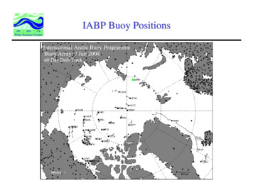
According to the HTM theory, the position of CL point in flank face grinding canbe expressed in the following formP'' 1 T1 n R1 n R''n g T''n g [ 0 0 0 1]T(30)4 Experiments and results4.1 Modeling experimentTo verify the validity of the proposed parametric modeling method, modelingexperiment was carried out in MATLAB. To validate the G1 continuity at the twojoints of a circular arc edge with the connected straight edge and conical helix edge,one TEMC with multi-structure features of tooth offset center and introversion of itsstraight edge was taken for example. The design values related to parametricmodeling of the cutting edge are shown in Table 1.Table 1Design values related to parametric modeling of the cutting edgeParameters2R (mm)re (mm)h (mm)η ( )κ ( )β ( )Design values201.50.244.539The calculated coordinates of J on c by substituting t1 0 into Eq. (6) is set as J 2c.The calculated coordinates of J on b by substituting θ π/2 η into Eq. (15) is set asJ 2b. The calculated coordinates of I on b by substituting θ κ into Eq. (15) is set asI 2b. The calculated coordinates of I on a by substituting ϕ 0 into Eq. (19) is set asI 2a. The calculated unit tangential vector of c at J by Eq. (5) is set as τJ 2c. Thecalculated unit tangential vector of b at J by substituting θ π/2 η into Eq. (16) is setas τJ 2b. The calculated unit tangential vector of b at I by substituting θ κ into Eq. (16)is set as τI 2b. The calculated unit tangential vector of a at I by substituting ϕ 0 intoEq. (20) is set as τI 2a. The modeling parameters of one tooth are shown in Table 2 andthe result in MATLAB is shown in Fig. 9.Table 2Modeling parameters
EquationsConditionsParametersCalculated valuesEq. (6)t1 0J 2c (mm)[8.3341, 1.0504, 1.4963]TEq. (15)θ π/2 ηJ 2b (mm)[8.3341, 1.0504, 1.4963]TEq. (15)θ κI 2b (mm)[10.0000, 0.0000, 0.1177]TEq. (19)ϕ 0I 2a (mm)[10.0000, 0.0000, 0.1177]TEq. (5)\τJ 2c[-0.9924, -0.1014, -0.0698]TEq. (16)θ π/2 ητJ 2b[-0.9924, -0.1014, -0.0697]TEq. (16)θ κτI 2b[-0.0610, 0.6293, 0.7748]TEq. (20)ϕ 0τI 2a[-0.0610, 0.6293, 0.7748]TFig. 9Modeling result of the bottom edge and the conical helix edge in MATLABThe calculated and modeling results validate the G1 continuity at the two jointsand prove the accuracy of the parametric modeling method.4.2 Grinding experimentThe machining accuracy of the grinding tool path was verified by the grindingexperiment. The parameters of the grinding wheel profile and grinding process areshown in Table 3. The allowable absolute errors of machining are 0.1mm/0.5 .Table 3Parameters of the grinding wheel profile and grinding process
Grinding processRake face grindingFlank face grindingParameters of grinding wheelShapeTypeRg (mm)Hg (mm)αg ( )ν( )V-shapeCup-shape12V911V95050253245307560Based on the mathematical models of TEMC, the grinding tool path in grindingof the tested TEMC was calculated by the grinding method put forward. Part of thegrinding tool path file obtained by the grinding method put forward is shown below“.GOTO/34.687784, -1.083085, -3.482481, -0.089849, 0.769583, -0.632194GOTO/34.688929, -1.095449, -3.472860, -0.089220, 0.769622, -0.632236GOTO/34.690062, -1.107808, -3.463239, -0.088592, 0.769661, -0.632276GOTO/34.691183, -1.120164, -3.453619, -0.087964, 0.769700, -0.632316GOTO/34.692292, -1.132515, -3.444000, -0.087335, 0.769740, -0.632355GOTO/34.693389, -1.144862, -3.434381, -0.086707, 0.769780, -0.632393GOTO/34.694474, -1.157205, -3.424763, -0.086079, 0.769820, -0.632430GOTO/34.695548, -1.
Research on parametric modeling and grinding methods of bottom edge of toroid-shaped end milling cutter Lei Han1, Xuefeng Cheng1, Lei Jiang1, Rong Li1, Guofu Ding1, Shengfeng Qin2