Transcription
To appear in the proceedings of I3D 2001A Projective Drawing SystemOsama TolbaJulie DorseyLeonard McMillanLaboratory for Computer ScienceMassachusetts Institute of Technology, Cambridge, MA it.eduAbstractWe present a novel drawing system for composing and renderingperspective scenes. Our approach uses a projective 2D representation for primitives rather than a conventional 3D description. Thisallows drawings to be composed with the same ease as traditional illustrations, while providing many of the advantages of a 3D model.We describe a range of user-interface tools and interaction techniques that give our system its 3D-like capabilities. We providevanishing point guides and perspective grids to aid in drawing freehand strokes and composing perspective scenes. Our system alsohas tools for intuitive navigation of a virtual camera, as well asmethods for manipulating drawn primitives so that they appear toundergo 3D translations and rotations. We also support automaticshading of primitives using either realistic or non-photorealisticstyles. Our system supports drawing and shading of extrusion surfaces with automatic hidden surface removal and highlighted silhouettes. Casting shadows from an infinite light source is also possible with minimal user intervention.CR Categories: I.3.3 [Computer Graphics]: Graphics Utilities—Graphics Editors; I.3.6 [Computer Graphics]: Methodologies andTechniques—Interaction TechniquesKeywords: Image-based Modeling and Rendering, Misc. 2Dgraphics, Non-Euclidean Spaces, Non-Photorealistic Rendering1IntroductionThe advent of computer graphics has greatly influenced many aspects of architectural drafting. Construction drawings, in the formof plans, sections, elevations, and details, are seldom drawn byhand today. In addition, hand-crafted physical models, traditionally used for client presentations, have been largely replaced withthree-dimensional computer models and walk-throughs. Perspective drawing, which was once an important technique for exploringand presenting designs, is virtually obsolete due to the speed andflexibility of today’s CAD systems. However, 3D modeling systems are generally cumbersome to use, and ill-suited for the earlystages of design where freehand sketching is often more appealing.Traditional perspective drawings are difficult to construct [3].Only a skilled illustrator can make a drawing with correct proportions. Furthermore, many construction lines are required to achievethis proportionality, making the process laborious. In addition, theviews they depict are static, which reduces their 3D impression.Proper shadow construction and shading are also time-consuming.Finally, like all drawings on paper, they are difficult to edit or reuse.Our goal is to provide interactive techniques to support perspective drawing. This problem has been largely neglected in 2D computer graphics. Almost all current 2D graphics systems use drawingprimitives that are represented with Euclidean 2D points. The process of constructing a perspective drawing with these systems isnearly as tedious as with traditional media.We have developed a perspective drawing system that overcomesmany of the limitations of traditional perspective drawing and current 2D computer graphics systems. Our system retains the easeof-use of a 2D drawing systems, but its projective representationprovides additional 3D-like functionality. We intend this tool forapplications that often do not require actual 3D modeling, such asconceptual design, technical illustration, graphic design, and architectural rendering. In many cases, these applications strive to generate a single perspective view, or a set of views sharing a commonviewpoint.We use projective 2D points to compose various renderings of ascene and provide capabilities that are generally thought to require3D models. For example, our system supports perspective drawingguides, dynamic 3D-like viewing and object manipulation, sceneillumination and shading, and automatic shadow construction. Inaddition, shape modeling operations, such as the simulation of 3Dextrusion, can also be performed using projective 2D points.Our 2D representation does not allow us to simulate walkthroughs. While we are able to simulate single-object motion, it isnot possible to correctly simulate the motion of a group of objects(or the viewer). We use transformations of the image of a planarobject that are independent of its actual distance from the viewer.In order to transform images of multiple objects, however, we needrelative depth information, which our system does not support.1.1 Related WorkIn [12] we introduced a projective 2D point representation anddemonstrated that perspective scenes, drawn with freehand strokes,can be properly re-projected into new viewing directions with avariable field of view, thereby giving the drawing an immersive 3Dlike effect. In this work, we extend the projective 2D point representation to provide sophisticated tools for constructing perspectivegeometric shapes. The shapes can be shaded and made to cast shadows. We also provide tools to simulate the apparent 3D motion ofthese shapes within a scene.Projective representations underly all panoramic image-basedrendering (IBR) systems. For example, “QuickTime VR” represents environments with cylindrical panoramas and synthesizesnovel perspective views by providing an interface for panning, tilt-
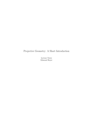
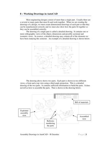
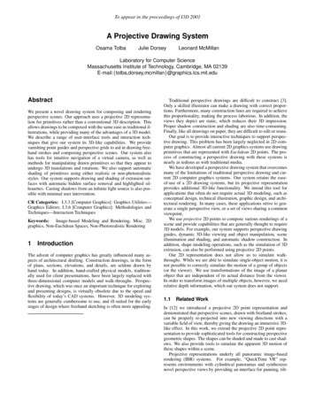
To appear in the proceedings of I3D 2001Viewing PlaneImplied Geometry(x, y, w)Unit SphereFigure 1: Two-dimensional drawing points are stored on the surfaceof the unit sphere centered about the viewer. They are displayed byprojecting them onto a user-specified viewing plane.ing, and zooming [1]. IBR systems typically facilitate navigationand visualization of a static scene. In our approach, we providecontrols for composing and editing illustrations.An active area of research is the development of sketching interfaces for 3D modeling [2, 6, 13]. These approaches acknowledgethe difficulty of using standard interfaces to build 3D models. Theirmain premise is that 3D shape can be inferred from freehand strokesthat follow a certain syntax, thereby allowing models to be generated very quickly. In our work, we do not infer 3D geometry, ratherwe make 2D drawings that are 3D-like.Non-photorealistic rendering (NPR) techniques apply a “handdrawn” look to photographs and 3D renderings by simulating manyconventional artistic methods. For example, when mimicking penand-ink styles, NPR uses hatching or stippling (a collection of shortstrokes) as a means to convey tonal variation [8, 10]. Another NPRtechnique is the use of silhouettes to emphasize shape [9]. Ourwork adopts silhouetting and selected pen-and-ink styles for rendering shaded perspective drawings automatically, although the actualrendering style is not the focus of our work.2Figure 2: A drawing of an outdoor plaza design shown as pointson the unit sphere centered about the viewer, and an array of viewsgenerated with our system from the same drawing. The bottom rowviews look in the same directions as the top row but tilt up.ing them to be composed with other matrix products, such as scaling and rotation. Projective points also permit re-projection to bedescribed as a simple matrix product. Another advantage is thatpoints at infinity are treated as regular points. For example, in a Euclidean system the intersection of two parallel lines must be treatedas a special case, while using projective points it is treated as aregular vanishing point. These properties of projective point representations give unique capabilities to our two-dimensional drawingsystem.Each stroke (or shape) in our system is stored as a list of suchprojective points obtained by back-projecting drawn image pointsto lie on the surface of a unit sphere centered about a viewpoint,while assuming that the drawing window subtends some solid angle viewing port. The stroke also supports auxiliary attributes suchas pen color and thickness. A drawing is a collection of strokesand shape primitives. Our projective representation allows us togenerate novel re-projections of the drawing (see Figure 1). Thesere-projections can be interpreted as rotating and zooming a cameraabout a single point in a three-dimensional space. However, reprojections of projective 2D points do not exhibit parallax changesresulting from changes in viewing position.We also use projective points to represent directions such as vanishing points, motion trajectories, infinite light sources, and surfacenormals. We refer the reader to [7] for a review of projective 2Dpoints and fundamental computational tools.Projective 2D pointsIn traditional drawing programs, primitives are specified via a collection of 2D points. Generally, these points are described by twocoordinates, which can be imagined to lie on a plane. The coordinates specify the position of a point relative to a specified origin andtwo perpendicular basis vectors. In mathematical parlance, suchpoints are considered Euclidean 2D points.This Euclidean representation of points is practically universalto all 2D drawing systems. There are, however, alternative representations of 2D points, which are not only more powerful thanEuclidean points, but also contain them as a subset. In particular,the set of projective 2D points can be represented using three coordinates in conjunction with the following rules: the origin is excluded, and all points of the form (a; b; c) and (a; b; c), where isnon-zero, are equivalent. The subset of projective points for whicha value of can be chosen, such that (a; b; c) ( a; b; 1), isthe Euclidean subset.There are several possible mental models for projective 2Dpoints, which are comparable to the plane of the Euclidean points.We adopt a model in which all projective points lie on a unit sphere.Thus, the preferred representation of the point (a; b; c) is the onewith chosen such that a2 b2 c2 1. We will further restrictall values of to be strictly positive. This additional restrictionresults in a special set of projective points called the oriented projective set [11].One advantage of projective 2D points is the ease with whichthey can be manipulated. Unlike Euclidean points, translations ofprojective points can be described by matrix products, thus allow-3The Perspective Drawing SystemWe start this section with descriptions of our system’s perspectiveviewing, guides, and primitives. Then we provide a detailed explanation of the aforementioned 3D-like object manipulation.2
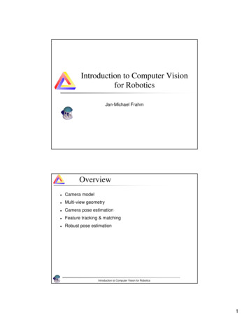
To appear in the proceedings of I3D 2001Figure 5: Examples showing the emulation of 3D translation (left)and rotation (right).3.2 Perspective GuidesFigure 3: The drawing system supports skewed perspective frustums that enable the user to draw on a frontal plane, such as inthe windows and bricks (shown with darker lines) drawn while facing the wall containing them. Without a skewed frustum this wallwould either lie outside the picture or appear small within a widefield of view.north, eastnorth-east, north-westnorth-east, northuser-specifiedThe use of a projective representation provides two new types ofvisual guides beyond the rulers and regular grids used by traditional2D drawing systems: vanishing point guides and perspective grids.Vanishing points are traditionally used as directional guides aswell as a means for geometric construction. We maintain them inour system for use as guides when drawing lines and rectangles. Wealso use vanishing points throughout this paper to compute variousdirections and object points.Our drawing system supports all of the conventional perspectiveview categories, such as “single-point,” “two-point,” and “threepoint” perspective, since the viewing direction can be changed dynamically, thereby transforming single-point perspective into twoor three-point perspective, and vice-versa. In fact, vanishing pointscan be specified in arbitrary directions, which need not even be orthogonal (see Figure 4).Vanishing points are directions represented by points on the unitsphere. They can be visualized as poles of a sphere centered aboutthe viewer. When projected onto the viewing plane, the longitudinal lines of the sphere appear as straight lines converging at thevanishing point, providing the desired visual effect.We also provide perspective grids in our system. The system automatically adjusts the grids to align with any two of the currentlyactive vanishing points. Grids, like vanishing points, can lie in general positions. This provides the interface necessary for drawingviews containing parallel lines, rectangles, boxes, etc. (see Figure4).Figure 4: We provide flexible vanishing points and perspectivegrids as visual guides. Users may select from built-in direction orspecify arbitrary ones. The “rectangle” tool respects the currentvanishing points as well as the normal to the plane they define.3.3 Perspective Shape PrimitivesIn addition to basic freehand drawing and straight lines, we support higher level shape primitives such as “perspective rectangles”(images of 3D rectangles), which the user specifies with two cornerpoints. General-shape closed polygons are also supported. Suchprimitives can have solid color for depicting non-transparent objects. When these primitives overlap, the order in which they aredrawn is used to convey occlusion. As with current 2D drawingprograms, the user can adjust this stacking order at any time.3.1 Perspective ViewingIn [12] we described how the re-projection of points (see Figure 2)allows for a virtual camera interface that provides instant panning,tilting, and zooming, similar to the QuickTime VR interface [1]. Inaddition to rotation and zooming, we provide controls for movingthe image center, thereby allowing the user to work on parts of thedrawing that would otherwise lie outside the field of view, or be toosmall if the field of view were made very wide. For example, whena user orients the view such that a chosen plane is viewed frontally(i.e. parallel to the viewing plane), the plane may be located outside the field of view. The user may then use the “image center”tool to bring the plane into the picture in order to draw “on it” proportionately. Useful examples include drawing bricks and windowson a facade (see Figure 3). In computer graphics terminology, thisoperation yields a skewed perspective frustum.3.4 Perspective Shape ManipulationThe drawing system supports manipulations of shape primitivesthat appear as 3D rigid-body translations and 3D rotations. Thesemanipulations provide flexibility and, together with copy/paste operations, they facilitate the creation of scenes containing symmetricor repeating elements (see Figure 5).In order to carry out these operations we use projective 2D pointsand surface normals, which the system automatically infers fromuser input. For example, the surface normal for a 3D rectangleviewed in perspective is simply the cross product of its two vanishing points (see Figure 6). In addition to their use in shape manipu-3
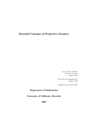
To appear in the proceedings of I3D 2001Figure 6: Surface normals are inferred by computing the vectorcross product of any two vanishing points associated with the 3Dplane. The line joining the two vanishing points is the image ofthe “line at infinity” of that plane, along which all of its vanishingpoints must lie. It can be envisioned in the spherical model as agreat circle perpendicular to the normal direction.Figure 7: Apparent translation of the plane as it is carried out in oursystem: Image points are transformed (warped) using a homography that is inferred from two input points (m, m0 ) and the surfacenormal. The motion trajectory is selected by the user from a list ofactive vanishing points.lation, surface normals are also crucial for performing other operations, such as modeling of aggregate shapes, shading, and shadowprojection.In projective geometry, each point has a dual—a line whose coefficients equal the point’s coordinates. The dual to a point representing the normal to a 3D plane plays a special role. Suppose thevector (a; b; c) represents the normal to a 3D plane. Its dual is theprojective 2D line ax by cw 0. We can envision this lineas an equatorial great circle whose pole is (a; b; c). Clearly, pointson this circle represent all directions parallel to the 3D plane, representing ideal (rather than Euclidean) 3D points at infinity. Thus,the line dual to the plane’s normal is the image of the line at infinity associated with the plane, of which we make frequent use. Forexample, we arrive at the direction of a 3D line that lies in a given3D plane by computing the “vanishing point” at the intersection ofthe line’s 2D image with the image of the plane’s line at infinity.Since in a 2D projective setting we have no knowledge of thedistance d from the viewpoint to the surface or the actual displacement of the plane Æ , we deduce a new quantity Æ d. Thisyields a single-parameter family of homographies compatible withthe translation of a 3D plane:T( a'bab(3)(4)m0 t (m t):This is an equation of the form: a b (vector a is -times vectorb), the solution for which is:0 km tk ; sign( ) sign((m0 t) (m t)):km tkIn our application, is always positive. We then rewrite Equation 4) ; and solve for as shown in Equationas: 0 (3.Note that 0 in the denominator of Equation 3 meansthat if the plane passes through the origin (d 0), or is viewed“edge-on,” the image of the planar shape is reduced to a line. Inthis case we cannot use a homography to simulate 3D motion.m(1)H ' I Æ tnT ;dtmn m tn m3.4.2 Apparent rotationwhere I is the 3 3 identity matrix, is the motion trajectory, Æ isthe translation distance, and is the surface normal of the moving d.plane, whose initial equation in 3D space isn m)):tdenotes , and is an arbitrary scale factor.whereAs mentioned in [7], the image of a translating 3D plane is transformed by the following homography: sign(t (m0where is a scale factor that we must determine before we cansolve for . First, we eliminate by taking the cross product ofEquation 4 with :wm0 ' H m;) m0 (I tnT )m m t(n m);010 1h11 h12 h13x @ h21 h22 h23 A @ y A ;or0 mk km; sign( (n m)The value of is given in the following derivation. From Equations1 and 2 we get: h31 h32 h33(2)mmWe provide an intuitive user interface for simulating 3D translationsof planar objects. The user selects a vanishing point as the motiontrajectory (direction of translation) then uses a pointing device to“drag” the object along this trajectory. Note that this operation requires no knowledge of distance or depth of the object, as may initially be imagined. It is possible to carry out this transformation onthe image of a plane knowing only its surface normal.We use mappings of the projective plane, represented by the unitsphere, to accomplish this transformation. Such a mapping is oftenreferred to as a collineation or homography H . It can be thought ofas a warping function applied to any object’s points through multiplying them by a 3 3 matrix as follows:y0w0' I tnT :All the quantities on the right-hand side of Equation 2 are knownexcept for the scalar parameter , which can be inferred from asingle pair of points ( ; 0 ) given the location of a point on thesurface before and after translation. Such a pair can be specifiedusing the pointing device, and must be constrained to lie on theselected trajectory, hence the single degree of freedom (see Figure7). We determine as follows:3.4.1 Apparent translationx0 !)As with apparent translation, the apparent rotation of a 2D perspective primitive about a fixed point, or pivot, can be simulated usingn P4
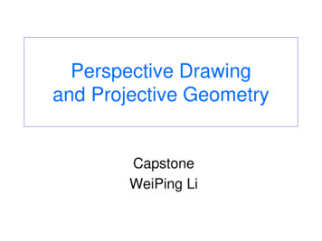
To appear in the proceedings of I3D 2001Figure 8: The rotation angle is inferred from a pair of input points(m, m0 ) indicating the position of a point before and after rotation.The point rotates in a plane perpendicular to the rotation axis. Byextending the lines mp and m0 p to the rotation plane’s line at infinity we get the directions t and t0 , which completely specify therotation angle.Figure 10: An extrusion shape is created by making a copy of thebase stroke and transforming it via a pseudo-3D translation alongthe extrusion direction. The normal of each facet is computed byintersecting the line joining mi and mi 1 with the base stroke’sline at infinity in order to determine a vanishing point vi , and thencomputing the normal as the cross product of this vanishing pointwith the extrusion trajectory.Figure 9: Apparent rotation of the plane is carried out in two steps:In the first step, the plane is rotated about the viewpoint. Then,using an apparent 3D translation, it is moved back to the pivot point.Figure 11: By default, the extrusion trajectory is perpendicular tothe base stroke. However, skewness can be introduced by shiftingthe extruded stroke in any chosen direction.homographies. For example, a perspective rectangle can appearto revolve about an arbitrary axis passing through a user-selectedpivot.An intuitive user interface allows the user to specify the rotationparameters. First, the user selects the axis from a list of active directions (vanishing points) and uses the pointing device to specify thepivot. Then the rotation angle is specified by dragging the pointingdevice about the pivot. For proper visual feedback, we make thepointing device appear to orbit in a 3D plane perpendicular to therotation axis and passing through the 3D pivot. Therefore, we inferthe rotation angle from the change in the direction of the imaginary 3D line joining the pivot, whose image is , and the pointingdevice, represented by and 0 (see Figure 8):m0 ' T ( :p00 ! p)m00 :Thus, the desired apparent rotation homography is a compositionof a 3D rotation matrix and a pseudo-3D translation homography:m0 ' T ( )R(a; )m:pm m sin 1 (kt t0 k); sign( ) sign((t t0 ) a);where t and t0 represent the above-mentioned direction before and4In this section we show how complex aggregate shapes can be modeled under this framework using shaded 2D polygons. We haveimplemented extrusion shapes as an example of such aggregateshapes. The principles described here are potentially applicable toother shapes as well, such as surfaces of revolution.after the rotation, given by:t ' (m p) a; t0 ' (m0 p) a:Once we have established the rotation axis, pivot and angle, werotate the object in two conceptual steps (see Figure 9):4.1 Extrusion1. In the first step, we rotate the object about the viewpoint (atthe origin of the world) using the rotation axis and angle desired for the local rotation. All object points, including thepivot itself, move to an intermediate position:The user draws a freehand “base stroke” and selects the extrusiontrajectory from the list of active vanishing points, then drags thepointing device to specify the magnitude of the extrusion. The system responds by making a copy of the base stroke, which we callthe “extruded stroke,” and applies apparent 3D translation to thiscopy using a variant of Equation 2:m00 R(a; )m:2. Next, we use apparent 3D translation (Equation 2), where00 , to “move the object back” to the original pivot:p pAggregate Shapest'T(5e)' I e enT ;
To appear in the proceedings of I3D 2001Figure 12: Geometry of the 3D planes used in extrusion.ewhere e is inferred from the dragging action and is the selectedextrusion trajectory. Segments of the new extruded stroke are connected to corresponding ones in the base stroke, thereby formingthe facets of the shape.This approach assumes that the base stroke represents a planarcurve in 3D space. By default, the user interface initially assignsthe base stroke’s normal as the extrusion direction. Normals to thefacets are inferred from vanishing points (see Figure 10), allowing for shading and shadow projection. Later, the user may shift theextruded stroke in any direction, thereby simulating a skewed extrusion shape (see Figure 11). The extrusion direction is re-computedas the intersection of any two facet sides connecting the base andextruded stroke. Facet normals are also updated using this new extrusion direction.Figure 13: An extrusion shape is rotated in several steps: First, boththe base and extruded strokes are rotated about their first points.The first facet is also rotated in order to determine the final positionof the extruded stroke (top). Then the extruded stroke is moved tothe correct position using the first facet as guide (bottom).4.1.1 Apparent TranslationWe also provide the ability to move an extruded shape in the sceneusing the same interface that we described for planar objects (Section 3.4.1). The apparent collective motion of the aggregate shape isperformed using two homographies: T ( ) and T ( 0 ) for the baseand extruded strokes respectively. We determine the base stroke’sparameter directly from user input as described in the planar object case, while the parameter 0 for the extruded stroke can bedetermined as follows:0 1 Figure 14: An edge of an extrusion shape is determined to be on thesilhouette if its neighboring facets are drawn in opposite directions.4.1.2 Apparent Rotatione n) :e(Rotation of an extruded shape about a pivot is also possible. Anypoint could serve as the origin of the rotation. For simplicity, wechoose the pivot to be the first point in the base stroke. We performthe rotation in a series of steps (see Figure 13):Derivation: Suppose that the imaginary 3D curve represented by d, andthe base stroke lies in a 3D plane whose equation is0 d0 . From Figurethe extruded curve lies in a parallel plane:12 we can deduce that:n Pn Pd0 d Æe (e n);Æe ;d 2. Rotate the extruded stroke about its first point. This results inan intermediate position for the extruded stroke.(5)where Æe is the extrusion distance. From our definition ofSection 3.4.1, we have:e 1. Rotate the base stroke about the rotation pivot.Æt ;d0 Æt ;d0Æt:in3. Rotate the first facet of the shape about the rotation pivot inorder to establish the correct positions for the first and secondpoints in the extruded stroke.(6)where Æt is the translation distance. By substituting the value of d0from Equation 5 into 6, we have:0 d Æe (e n)4. Move the extruded stroke from its intermediate position to thecorrect position determined in step 3. For this operation, weuse apparent 3D translation (Equation 2), where01 ) ( 202 ).( 1t' m m m mSince Æe d e (Equation 6), we have:0 d dÆte(e n) Æt d1 e n)e(4.2 Silhouettes 1 e n)e(Rather than drawing all facets of an extrusion, and in keeping withthe hand-drawn look, we have developed techniques to highlightthe boundaries and silhouettes of extrusion shapes. Silhouettes of:6
To appear in the proceedings of I3D 2001C OMPUTE -S o-Screen-CoordinatesStippleDensityMaxDensity (1 min(0; n s))NumStipplesStippleDensity Bounding-Box-Areafor i1 to NumStipplesdo BeginPoint (Random-Length StippleDirection)Clip-Stipple-to-Shape; Back-Project-Stipple; Add-to-StippleList Figure 17: Pseudo-code for stippling algorithm.Figure 15: Points on a plane make a greater angle with its normalas they move farther away from the viewpoint. This observation isused to draw an extrusion shape in a back-to-front order.Figure 16: The stippling direction is determined from the surfacenormal and light direction.Figure 18: Shadows are projected automatically using the surfacenormals and light source direction (shown with faded lines). Theshadow is initially attached to the object casting the shadow (top).Later the user may drag the shadow in order to simulate distance between the shadow-casting and shadow-receiving objects (bottom).The system automatically re-projects the shadow during this dragging operation.faceted surfaces lie at the edges between two facets, one of which isfront-facing while the other is back-facing [9]. A simple 2D methodcan be used to determine the existence of this condition [5]. If theedges of two neighboring facets are drawn in opposite directions(i.e., clockwise vs. counter-clockwise), the shared edge is on thesilhouette (see Figure 14).4.3 VisibilityAlthough inter-object visibility cannot be unambiguously resolvedfor 2D representations, intra-object visibility can be determined insome instances. For example, the facets of an extrusion shape canbe drawn in a back-to-front order using the simple observation thatpoints on the base plane make a greater angle with the plane’s normal as they move farther away. For example, in Figure 15, we have i ; therefore, a facet based at j is potentially ocjcluded by another based at i (assuming the extrusion shape is notskew). Based on this dot product criteria, we create a sorted listof facet indexes that we use for rendering. Re-sorting of this list isnecessary if the object undergoes apparent translation or rotation.m n m n5mis consistent with that of the manual illustrations in [3]. Instead ofLambertian shading, it generates four levels of grey according tothe following rules: Shadows are hatched with maximum density,objects facing away from the light are hatched with lighter density,and light stippling is applied to objects that are dimly lit (i.e., theangle between the normal and the light source is greater than 45degrees).Due to the computational overhead of artistic shading (about 2seconds for a complex scene), we adopt the following strategy:Shading strokes are computed in screen coordinates when thereis no camera motion, then back-projected and stored on the unitsphere. As the user rotates the camera, the stored strokes are usedto render the scene. Although the stored shading becomes somewhat inaccurate during camera motion, this strategy provides adequate feedback during scene navigation and avoids the flickeringthat would result from re-computing the strokes during camera moti
three-dimensional computer models and walk-throughs. Perspec-tive drawing, which was once an important technique for exploring and presenting designs, is virtually obsolete due to the speed and flexibility of today’s CAD systems. However, 3D modeling sys-tems are