Transcription
Electric BoilersBTH ULTRAModels ranging from 12 kW to 36 kW 208/240 Volts (1 phase)INSTALLATION & OPERATION MANUALYour BTH ULTRA Electric Boiler has been carefully assembled and factory tested to provideyears of trouble-free service. The following information and safety measures are provided toenable proper installation, operation, and maintenance of this product.It is imperative that all persons who are expected to install, operate or adjust this boiler shouldread these instructions carefully.The accessories included with the boiler are shipped within the cabinet of the unit.Any questions regarding the operation, maintenance, service or warranty of this electric boilershould be directed to the supplier.When all installation steps have been completed, keep this installation manual in a safe place(close to the boiler) for future reference.THERMO 2000 INC.Revision: May 2022Printed In Canada
Table of contentsSection 1: Technical specifications . 4Table 1: Technical data on boilers operating at 240 Vac /1ph1 : . 4Table 2 : Boiler connections and dimensions (12-24 KW) . 5Table 3 : Boiler connections and dimensions (27-36 KW) . 5Section 2: INTRODUCTION. 62.1 LOCAL INSTALLATION REGULATIONS . 62.2 CORROSIVE ENVIRONMENT. 62.3 INSPECTION UPON RECEPTION . 62.4 TO BE CHECKED . 6Section 3: INSTALLATION. 73.1 SAFETY MEASURES . 73.2 LOCATION. 73.3 CLEARANCES . 7Table 4: Boiler Clearances . 73.4 PIPING INSTALLATION . 83.4.1 Type of installation . 83.4.2 Boiler piping connection . 12Local codes may dictate the type of pipe to be used for the connections. 12Install isolating valves to facilitate maintenance . 123.4.3 Pressure relief valve . 123.4.4 Expansion tank . 123.4.5 Water pressure regulator . 123.4.6 Air eliminator. 123.4.7 Circulating pump . 12Table 5: Temperature rise vs flow rate (GPM) . 123.4.8 Drain valve. 123.4.9 Strainer . 123.4.10 Dual Energy piping . 133.5 ELECTRIC CONNECTIONS . 133.5.1 Main Electric supply . 133.5.2 Electrical supply of External accessories . 143.5.3 Outdoor temperature sensor . 143.5.4 Connecting the thermostat and pump. . 143.5.4 Dual-energy connection with an auxiliary boiler. . 15Section 4: ADJUSTMENT OF THE CONTROLLER . 184.1 INTRODUCTION . 184.2 DISPLAYED INFORMATION . 184.3 OPERATION OF THE INTERFACE . 194.4 OPERATION IN “FIXED BOILER TEMPERATURE SET POINT” . 194.5 OPERATION WITH “OUTDOOR RESET”: . 194.6 PURGE DELAY OF THE PUMP . 204.7 AUTOMATIC HEATING SHUT DOWN . 204.8 CONFIGURATION OF THE CONTROLLER . 204.9 ADJUSTMENTS OF THE TARGET TEMPERATURE BY THE USER: . 224.10 BOOST SYSTEM OPERATION . 224.11 OPERATION IN DUAL-ENERGY: . 23Section 5: START UP OPERATION . 245.1 PREPARATORY STEP . 245.2 STARTUP & INSPECTION. 245.3 COMPLEMENTARY CHECKS ON DUAL-ENERGY INSTALLATIONS . 24BTH ULTRA Electric Boilers Installation & Operation manual (Revision: May 2022)2
Section 6 MAINTENANCE . 246.1 INTRODUCTION . 246.2 AT ALL TIMES . 256.3 TWICE A YEAR . 256.4 ANNUALY . 25Section 7- TROUBLE SHOOTING . 267.1 TROUBLE SHOOTING TABLE . 267.2 SPARE PARTS . 28BTH ULTRA LIMITED WARRANTY . 31Figure 1 : Boiler dimensions (12-24 KW) . 5Figure 2 : Boiler dimensions (27-36 KW) . 5Figure 3 : Mounting positions . 8Figure 4 : Typical Installation on heating floor . 8Figure 5 : Typical installation on fin-tube baseboards with zoning valves . 9Figure 6 : Multi-pump zoning. 9Figure 7 : Typical Installation in Dual-Energy Series . 10Figure 8 : Typical installation with three way valve . 10Figure 9 : Zoning with Multiple pumps . 15Figure 10 : Zoning with motorized valves . 15Figure 11 Connexions without three way valve . 16Figure 12 : Connexions with three way valve . 16Figure 13 : Wiring diagram (12-24 KW) . 17Figure 14 : Wiring diagram (27-36 KW) . 17Figure 15 : UltraSmart Controller Display . 18Figure 16 : UltraSmart Control Module . 19Figure 17 : Back of the controller . 21Figure 18 : Spare parts (front, 12-24 KW). 28Figure 19 : Spare parts (top, 12-24 KW) . 28Figure 20 : Spare parts (front, 27-29 KW). 29Figure 21 : Spare parts (top, 27-36 KW) . 29Figure 22 : Spare parts (front, 33-36 KW). 30BTH ULTRA Electric Boilers Installation & Operation manual (Revision: May 2022)3
Section 1: Technical specificationsTable 1: Technical data on boilers operating at 240 Vac /1ph1 :Suggested size at 65.272.5872720.2272921.73336HeatingElements (240 V)StagesCableBreaker(Amp.)CuAl46470464807583.31004 x 3 KW2 x 3 KW 2 x 4.5 KW4 x 4.5 KW4 x 5 KW4 x 6 KW44497.9112.56 x 4.5 KW6291041204 x 5 KW 2 x 4.5 KW64321x1or2 x 641x1or2 x 642201 x 00or2 x 441 x 00or2 x 441001101252 x 80or1502 x 80or1752533119.6137.562 x 452 x 252 x 1002736130.515062 x 452 x 252 x 1003 x 5 KW 3 x 6 KW6 x 6 KWsupply 120/240V or 120/208V – 1ph (L1-N-L2) with three conductors and a ground or a supplywith two conductors 240V or 208V – 1ph (L1-L2) with a ground if the application does not require a 120Velectrical supply for external accessories such as a pump, etc2 Add the amperage of the circulating pump and other external accessories if they are connected to theboiler (max. 5A).3A higher cable size could be required. In all cases the local electrical code has priority. The electrician hasthe responsibility to select the appropriate size.4Two main terminal blocks that could be converted to one on the job site.5Two double pole breakers1Electrical1 kW 3412 BtuBTH ULTRA Electric Boilers Installation & Operation manual (Revision: May 2022)4
Table 2 : Boiler connections and dimensions (12-24 KW)ConnectionsInlet (return)Outlet (supply)Safety valveDraining valveShipping weight1 “ NPT Fem1 “ NPT Fem1“reduced to 3/4 “ NPT Fem1“reduced to 3/4 “ NPT Fem63 lbsItemDimension 3/4201-1/2Figure 1 : Boiler dimensions (12-24 KW)Table 3 : Boiler connections and dimensions (27-36 KW)ConnectionsInlet (return)1 ¼ “ NPT FemOutlet (supply)1 ¼ “ NPT FemPressure relief valve 1 ¼“reduced to 3/4 NPTFemDrain valve1 ¼“reduced to 3/4NPT FemShipping weight75 lbsItemDimension 1-5/8201-3/4Figure 2 : Boiler dimensions (27-36 KW)BTH ULTRA Electric Boilers Installation & Operation manual (Revision: May 2022)5
!General Safety PrecautionsBe sure to read and understand the entire Installation & operation manual before attempting toinstall or to operate this water heater. Pay particular attention to the following General SafetyPrecautions. Failure to follow these warnings could cause property damage, bodily injury or death.Should you have any problems understanding the instructions in this manual, STOP, and get helpfrom a qualified installer or technicianSection 2: INTRODUCTION!WARNINGThese important safeguards andG instruction appearing in this manual are not meant to cover allpossible conditions and situations that may occur. It should be understood that common sense,caution and care are factors which cannot be built into every product. These factors must besupplied by the person(s) caring for and operating the unit.2.1 LOCAL INSTALLATIONREGULATIONSThis electric boiler must be installed inaccordance with these instructions and inconformity with local codes, or in the absence oflocal codes, with the National Plumbing Code andthe National Electric Code, current edition. In anycase where instructions in this manual differ fromlocal or national codes, the local or national codestake precedence2.2 CORROSIVE ENVIRONMENTThe electric boiler must not be installed near anair duct supplying corrosive atmosphere or withhigh humidity content.When a boiler defect is caused by suchconditions, the warranty will not apply2.3 INSPECTION UPON RECEPTION2.4 TO BE CHECKEDPlease check the identification tag on the unit tomake sure you have the right model (Capacity inkilowatt, voltage, number of phase and ASMEconstruction or not ASME).List of components shipped with theunit: Pressure relief valve set at 30PSI. Drain valve. Two reducer fittings Temperature & pressureindicator Outdoor temperature sensor InstallationandoperatingmanualInspect the electric boiler for possible shippingdamage.The manufacturer’s responsibilityceases upon delivery of goods to the carrier ingood condition. Consignee must file any claimsfor damage, shortage in shipments, or nondelivery immediately against carrier.BTH ULTRA Electric Boilers Installation & Operation manual (Revision: May 2022)6
Section 3: INSTALLATIONThe manufacturer’s warranty does not cover any damage or defect caused by installation, orattachment, or use of any special attachment other than those authorized by the manufacturer into,onto, or in conjunction with the water heater. The use of such unauthorized devices may shortenthe life of the boiler and may endanger life and property. The manufacturer disclaims anyresponsibility for such loss or injury resulting from the use of such unauthorized devices3.1 SAFETY MEASURESAll installation will include the supplied pressurerelief valve which limits the maximum operatingpressure to 30 psi (207 kPa).This electric boiler is designed to be installed ona circuit operated between 50 F to 190 F (10 Cto 90 C) and at a maximum operating pressure of30 psi (207 kPa).The unit in designed solely to be used on a closeloop hydronic heating system. The heattransfer solution must be a solution of water or ifa freeze protection is required, a mix solutionWater/propylene glycol specially made forhydronic heating systems and having amaximum concentration of 50% (do not useplumbing or automobile glycol).The boiler is equipped with an automatic highlimit temperature control set at 210 F 99 C) andsome models have a second limit devicemanually re-settable set at 227F (108C). If theheating distribution system on which the boiler isinstalled requires a high limit controller having alower setting, this controller will be added to thesystem and connected in series with the factoryinstalled limit control.3.2 LOCATIONThe electric boiler should be installed in a clean,dry location. Long hot water lines should beinsulated to conserve water and energy. Theelectric boiler and water lines should be protectedfrom exposure to freezing temperature.The boiler can be mounted vertically orhorizontally (see fig.3) directly on a solid surfacewith 4 adequate screws inserted in the providedboiler openings. Make sure it is properly leveledThe electric boiler must be located or protectedso as not to be subject to physical damage, forexample, by moving vehicles, area flooding, etc.All models can be installed directly on acombustible wall and into an alcove. The locationmust have sufficient ventilation to maintain anambient temperature not exceeding 90 F (32 C).CAUTION!The electric boiler should not be located in anarea where leakage of the tank or waterconnections will result in damage to theadjacent area or to lower floors of thestructure. When such areas cannot beavoided, a suitable drain pan or nonflammable catch pan, adequately drainedmust be installed under the boiler.The pan must be connected to a drain.NOTE: Auxiliary catch pan MUST conform tolocal codes.3.3 CLEARANCESFor adequate inspection and servicing thefollowing minimum clearance is necessary:Table 4: Boiler ClearancesSidesElectric elements sideFront side of the boilerBack3 inches14 inches3 inches*0 inches*If the boiler is installed in a closed compartment,allow an access service opening and adequateventilation to maintain an ambient temperaturelower than 90 F/32 C.BTH ULTRA Electric Boilers Installation & Operation manual (Revision: May 2022)7
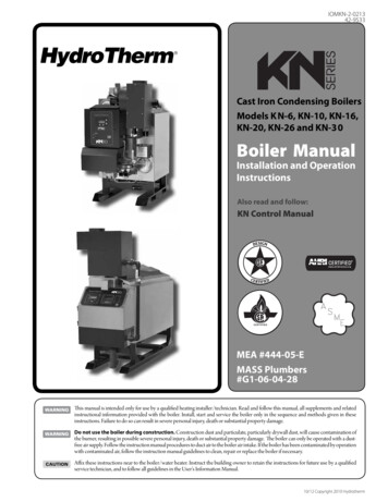
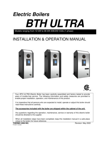
3.4 PIPING INSTALLATIONThe inlet and outlet piping of the boiler must be in conformity with the different configurations shownbelow. Make sure that the fluid flows is in the proper direction.Figure 3 : Mounting positions3.4.1 Type of installationYou will find below on figures 4 to 8 the typical piping arrangement for the two main types of installation.The first being as a self-operating unit and the others being connected to an auxiliary boiler in dual-energy.Figure 4 : Typical Installation on heating floorBTH ULTRA Electric Boilers Installation & Operation manual (Revision: May 2022)8
Figure 5 : Typical installation on fin-tube baseboards with zoning valvesFigure 6 : Multi-pump zoningBTH ULTRA Electric Boilers Installation & Operation manual (Revision: May 2022)9
Figure 7 : Typical Installation in Dual-Energy SeriesFigure 8 : Typical installation with three way valveBTH ULTRA Electric Boilers Installation & Operation manual (Revision: May 2022)10
Figure 9 - Typical Dual-Energy installation with a condensation boiler (1 zone)Figure 10 - Typical Dual-Energy installation with a condensation boiler (3 zones)BTH ULTRA Electric Boilers Installation & Operation manual (Revision: May 2022)11
3.4.2 Boiler piping connectionMake sure you connect the accessories and thepiping to the proper connection fittings as indicatedat figure 2 above and according to the selectedmounting position. The outlet and inlet boilerconnections are located on each sides. Theyconsist of 4 steel couplings (1”NPTF on 12 to 24kWmodels and 1-1/4”NPTF on 27 to 36kW) where thepiping connection will be made.Local codes may dictate the type of pipe to be usedfor the connections.Install isolating valves to facilitate maintenance3.4.3 Pressure relief valveThis component is supplied with the unit and mustbe installed on the boiler. It is designed toautomatically open at approximately 30 psi.to theappropriate connection according to the mountingposition.Connect the outlet of the relief valve downward to asafe location in case of discharge.The piping diameter used for the discharge pipingshall not be smaller than that of the valve outlet. Novalve of any type, restriction or reducer couplingshould be installed on the discharge line. Localcodes shall govern the installation of relief valves.3.4.4 Expansion tankThe expansion tank must be able to store theincrease volume of boiler water occurring when theboiler water increases in temperature. Themaximum allowable operating pressure is 30 psi(207 kPa). Contact your plumbing supply house forassistance.3.4.5 Water pressure regulatorThe boiler should be installed in such a way that itcan automatically be fed with water in the event ofa pressure drop.The minimum pressure obtained when the systemis cold is generally 12 psi (83 kPa).This accessory shall be equipped with one or morecheck valves to avoid all possibilities of the boilerwater returning to the potable water supply network(local regulation should be applied)3.4.7 Circulating pumpWater flow is required at all time when the boiler isoperating.The pump shall be selected such as to be able tosupply adequate flow in relation to the heatingdistribution system on which it will be connectedand the heating capacity of the boiler installed.Table below shows required flow in relation to thepower capacity of the boiler and the requiredtemperature drop in the heating distribution system.On System with baseboard heaters, 20 Ftemperature drop is normally recommended and onradiant floor application a value of 10 F is generallyused.Table 5: Temperature rise vs flow rate(GPM)ModelKWBTH ULTRA 12BTH ULTRA 15BTH ULTRA 18BTH ULTRA 20BTH ULTRA 24BTH ULTRA 27BTH ULTRA 29BTH ULTRA 33BTH ULTRA 36121518202427293336Diff. Temp.10oF8,210,212,313,716,418,420,522,524,7Diff. Temp.20oF4,15,16,16,88,29,210,211,312,3Your heating wholesaler shall be in good position torecommend the appropriate model for yourapplication.If the pump is supplied by the PP terminals of theboiler, its amperage plus the amperage drawn byother 120V external components must not exceed5A.3.4.8 Drain valveInstalled at the lowest part of the unit, it allows theboiler to be drained if defective components needto be replaced.3.4.9 Strainer3.4.6 Air eliminatorInstallation of manual or automatic air vents arerequired to eliminate all air from the boiler and theheating distribution system.The main air eliminator must be installed near theoutlet of the boiler on the highest point of the mainsupply piping. It is imperative to insure that all airpossibly located in the boiler be eliminated at alltime.This component could be required on old heatingdistribution systems made of steel or cast iron thatcould carry sediments and sludge. If suchsediments accumulate at the bottom of the boiler itcould be harmful to the heat transfer of theelements and generate premature failures.BTH ULTRA Electric Boilers Installation & Operation manual (Revision: May 2022)12
3.4.10 Dual Energy pipingPiping connections between the two boilers can bemade in parallel or in series as illustrated in fig. 7&8.When installed in parallel, a three way motorizedvalve (1”NPTF) is used to guide the heating systemreturn water toward the auxiliary boiler or the BTHULTRA electric boiler according to the operatingmode in demand. This way, the oil or gas boiler isnot maintained hot by the return water when theoperation is in Electricity.N.B.: Make sure to select the appropriate port A, Band AB when making the connection of the piping(see fig.8)3.5 ELECTRIC CONNECTIONS3.5.1 Main Electric supplyBoiler wiring and grounding must conform to theNational Electrical Code and to state or local coderequirements. The latter having precedence.Wire gauge must be properly sized by a qualifiedelectrician in such a way as to meet the nationalelectrical code.To do so, consult the boiler rating plate which willindicate the amperage drawn by the boiler at fullcapacity. Extra amperage will have to be added ifexternal electrical equipment are connected to theboiler.This value and the electrical code will be used todetermine the electric cable required together withthe appropriate breaker.Many other factors must be taken into considerationin the selection of the appropriate electrical materialsuch as the length and the type of cable used, theenvironment where the cable will be installed andthe type of the over-current protection used.Supply cables can be made of Aluminum or Copperand be rated for a minimum of 75oC (165oF).If aluminum cables are used, it shall be of anadequate size (generally bigger) and particularconsideration will have to be respected such as theuse of DE-OX inhibitors in order to meet theNational electrical code.If the boiler electrical supply is on 208V, the positionof wire terminal on the transformer connected to240V will have to be changed to 208V.The electrical supply can be done in two differentways depending on the necessity of supplying ornot external accessories (such as a pump) at120Vac.Alternative #1: A 120VAC electrical supplyis required to serve external accessories.Models 12 to 24 kWElectrical wiring must come from a 120/240 Vac/or120/208Vac -1ph “L1-N-L2-” circuit protected by aproperly sized breaker.The main terminal block of the boiler is suitable for#14 to #00 copper or aluminum wires rated for 75 C(165 F) min.Models 27 & 291. The main electrical supply comes from twoelectrical supply circuitsThe electrical supply may come from two circuits at240V or 208V/1ph/60Hz with one of the circuithaving a neutral conductor.The two circuits must be protected by a properlysized breaker (see table below giving the amperagedrawn by the boiler on each terminal block) inconformity with local electrical codes.Connections are made on the two main terminalblock inside the boiler.The boiler can then be operated at 50% of itsnominal capacity when the breaker supplying theelectric circuit connected to terminal block #2 isturned OFF during periods of low demand.These terminal blocks are suitable for #14 to #00copper or aluminum wires rated for 75 C (165 F)min.2. The main electrical supply comes from oneelectrical supply circuit)The boiler electrical boiler supply could come fromonly one circuit at 120/240 Vac or 120/208Vac1ph/60Hz L1/N/L2 where the cable size will notexceed AWG#00.All the factory connected wires to terminal block #2will have to be transferred to terminal block #1.Models2729AMPERE @ 208/240 VAC/1phTerminal Block #1 Terminal Block #249/56 Amps49/56AmpsOne terminal block 98/112A52/60 Amps52/60 AmpsOne terminal block 104/120AModels 33 & 36The electrical supply must come from two differentelectrical circuits. One circuit having threeconductors 120/240V or 120/208V “L1/N/L2” andthe other two conductors 240 or 208V “L1/L2”.Both circuits will need to be protected withappropriate breakers or fuse (see table belowgiving the amperage drawn by the boiler on eachbreaker) in conformity with local electrical codes.BTH ULTRA Electric Boilers Installation & Operation manual (Revision: May 2022)13
Connections are made directly on the two breakersinside the boiler.These breakers can receive copper or aluminumcable up to #1AWG.The boiler can then be operated at approximately50% of its nominal capacity when the breakersupplying the electric circuit connected to breaker#2 is turned OFF during periods of low demand.ModelModèle3336AMPERE @ 208/240 VAC/1phBreaker #1Breaker #22 x 5 KW, 1 x 6KW57/66 Amps3 x 6 KW65/75 Amps2 x 6 KW, 1 x 5KW61/70 Amps3 x 6 KW65/75 AmpsAlternative #2: No 120Vac electrical supplyis required to serve external accessories(pump is supplied by a separate circuitoutside the boiler)The electrical supply is made the same way asdescribed in alternative #1 excepting that it doesnot need the Neutral (N) conductor.3.5.2 Electrical supply of ExternalaccessoriesWhen the boiler is supplied with a 120V circuit, thetotal 120vac consumption of the boiler and externalaccessories must not exceed 5A.The maximum electrical consumption of 24vacexternal accessories connected to R&C terminalsmust not exceed 15VA.N.B.: The 24Vac supply of the boiler must not bemixed with another 24Vac external supply.3.5.3 Outdoor temperature sensorIf you want the
loop hydronic heating system. The heat must be installed under the boiler. transfer solution must be a solution of water or if a freeze protection is required, a mix solution Water/propylene glycol specially made for hydronic heating systems and having a maximum concentration of 50% (do not use plumbing or automobile glycol).