Transcription
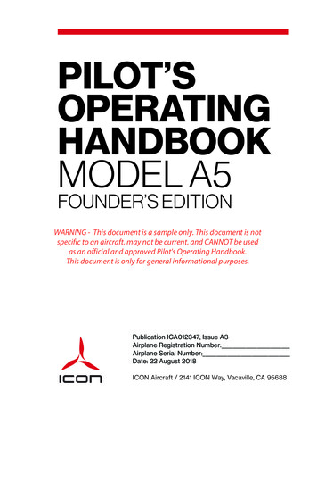
PILOT’SOPERATINGHANDBOOKMODEL A5FOUNDER’S EDITIONWARNING - This document is a sample only. This document is notspecific to an aircraft, may not be current, and CANNOT be usedas an official and approved Pilot's Operating Handbook.This document is only for general informational purposes.Publication ICA012347, Issue A3Airplane Registration Number:Airplane Serial Number:Date: 22 August 2018ICON Aircraft / 2141 ICON Way, Vacaville, CA 95688
ICON Aircraft, Inc.2141 ICON WayVacaville, CA 95688https://www.iconaircraft.comAll rights reserved. No part of this manual may bereproduced or copied in any form or by any meanswithout written permission of ICON Aircraft, Inc.SAMPLE DOCUMENT ONLY - Not For Use For Aircraft Operation, Actual Pilot's Operating Handbook, Or Flight Planning.II
RECORD OF MANUAL/HANDBOOK REVISIONS / ISSUE A3IIIRECORD OF MANUAL/HANDBOOK REVISIONSThis section gives a record of the Pilot’s Operating Handbookrevisions in the current issue series (Issue A, Issue B, etc.). Furtherdescription of the revisions by issue and chapter can be foundbelow.IssueDateChapter(s)A02 August 2017AllAdded ByICON AircraftA116 February 20183,4,7,9ICON AircraftA211 April 20182,3,4,7,9ICON AircraftA322 August 20182,4,7,8,9ICON AircraftISSUE A3The following are a list of revisions for Issue A3.Chapter 2 Corrected typo in the word ‘supplying’ in the warning forMinimum Load Rating of Cargo Restraints (Pilot Supplied) Updated text of Environmental Limitations Revised reference to FAA exemption number Corrected graphic font error in Secure Loose Objects placard Updated the ELT Remote Switch placardChapter 4 Updated text of Step Taxi/Normal Takeoff—WaterChapter 7 Updated text of Flight Controls Updated placard in ELT Remote Control and Audio Alert IndicatorChapter 8 Updated text of Cleaning and Care related to Corrosion InhibitorChapter 9 Updated FAA ExemptionSAMPLE DOCUMENT ONLY - Not For Use For Aircraft Operation, Actual Pilot's Operating Handbook, Or Flight Planning.ISSUE A3ICON A5 / PILOT’S OPERATING HANDBOOK
IVRECORD OF MANUAL/HANDBOOK REVISIONS / ISSUE A2ISSUE A2The following are a list of revisions for Issue A2.Chapter 2 Changed Complete Aircraft Parachute to ICON ParachuteSystem (IPS)Chapter 3 Changed Complete Aircraft Parachute to ICON ParachuteSystem (IPS)Chapter 4 Changed Complete Aircraft Parachute to ICON ParachuteSystem (IPS)Chapter 7 Changed Complete Aircraft Parachute to ICON ParachuteSystem (IPS)Chapter 9 Changed Complete Aircraft Parachute to ICON ParachuteSystem (IPS)ISSUE A1The following are a list of revisions for A1.Chapter 3 Small formatting changes Updated Electrical Fire in Flight Added Box-Canyon ReversalChapter 4 Updated Before Cockpit EntryChapter 7 Correct typos Updated ICON Parachute SystemChapter 9 Updated ICON Parachute SystemSAMPLE DOCUMENT ONLY - Not For Use For Aircraft Operation, Actual Pilot's Operating Handbook, Or Flight Planning.ICON A5 / PILOT’S OPERATING HANDBOOKISSUE A3
RECORD OF MANUAL/HANDBOOK REVISIONS / ISSUE AVISSUE AThe following are a list of revisions for Issue A.All Chapters Initial release of Founder’s Edition POHSAMPLE DOCUMENT ONLY - Not For Use For Aircraft Operation, Actual Pilot's Operating Handbook, Or Flight Planning.ISSUE A3ICON A5 / PILOT’S OPERATING HANDBOOK
VIRECORD OF MANUAL/HANDBOOK REVISIONS / ISSUE ASAMPLE DOCUMENT ONLY - Not For Use For Aircraft Operation, Actual Pilot's Operating Handbook, Or Flight Planning.ICON A5 / PILOT’S OPERATING HANDBOOKISSUE A3
LIST OF EFFECTIVE CHAPTERS /VIILIST OF EFFECTIVE CHAPTERSThe table below shows the current, effective chapters and dates inthis revision of the handbook (see previous section). The applicablehandbook issue is listed at the bottom corner of this page forreference.ChapterChangeDate0. IntroductionA002 August 20171. General InformationA002 August 20172. LimitationsA222 August 20183. Emergency ProceduresA211 April 20184. Normal ProceduresA322 August 20185. PerformanceA002 August 20176. Weight, Balance, andEquipment ListA002 August 20177. Description of Airplaneand SystemsA322 August 20188. Handling and ServicingA122 August 20189. SupplementsA322 August 2018SAMPLE DOCUMENT ONLY - Not For Use For Aircraft Operation, Actual Pilot's Operating Handbook, Or Flight Planning.ISSUE A3ICON A5 / PILOT’S OPERATING HANDBOOK
VIIILIST OF EFFECTIVE CHAPTERS /SAMPLE DOCUMENT ONLY - Not For Use For Aircraft Operation, Actual Pilot's Operating Handbook, Or Flight Planning.ICON A5 / PILOT’S OPERATING HANDBOOKISSUE A3
TABLE OF CONTENTSIXTable of ContentsCHAPTERRecord of Manual/Handbook Revisions . . . . . . . . . . . . . . . . .List of Effective Chapters . . . . . . . . . . . . . . . . . . . . . . . . .Introduction . . . . . . . . . . . . . . . . . . . . . . . . . . . . . . . . 0General Information . . . . . . . . . . . . . . . . . . . . . . . . . . . . . 1Limitations . . . . . . . . . . . . . . . . . . . . . . . . . . . . . . . . . .2Emergency Procedures . . . . . . . . . . . . . . . . . . . . . . . . . .3Normal Procedures . . . . . . . . . . . . . . . . . . . . . . . . . . . . .4Performance . . . . . . . . . . . . . . . . . . . . . . . . . . . . . . . . .5Weight, Balance, and Equipment List . . . . . . . . . . . . . . . . . .6Description of Airplane and Systems . . . . . . . . . . . . . . . . . .7Handling and Servicing . . . . . . . . . . . . . . . . . . . . . . . . . . .8Supplements . . . . . . . . . . . . . . . . . . . . . . . . . . . . . . . . .9SAMPLE DOCUMENT ONLY - Not For Use For Aircraft Operation, Actual Pilot's Operating Handbook, Or Flight Planning.ISSUE A3ICON A5 / PILOT’S OPERATING HANDBOOK
SAMPLE DOCUMENT ONLY - Not For Use For Aircraft Operation, Actual Pilot's Operating Handbook, Or Flight Planning.
INTRODUCTION / ASTM STANDARDS0-2CHAPTER 0Chapter 00INTRODUCTIONASTM Standards . . . . . . . . . . . . . . . . . . . . . . . . . . . . . . . . . . .Contact Information . . . . . . . . . . . . . . . . . . . . . . . . . . . . . . . .Data Location Information. . . . . . . . . . . . . . . . . . . . . . . . . . .Handbook Revisions . . . . . . . . . . . . . . . . . . . . . . . . . . . . . . . .Symbols. . . . . . . . . . . . . . . . . . . . . . . . . . . . . . . . . . . . . . . . . . . .0.10-20-30-30-30-4ASTM STANDARDSFAA-accepted consensus standards are utilized for the design,construction, and continued airworthiness of the ICON A5. Thisaircraft complies with the following ASTM standards:F2245Standard Specification for Design and Performance of a LightSport AircraftF2295Standard Practice for Continued Operational Safety Monitoring of a Light Sport AircraftF2746Standard Specification for Pilot’s Operating Handbook (POH)for Light Sport AirplaneF2972Standard Specification for Light Sport Aircraft Manufacturer’sQuality Assurance SystemThis Pilot’s Operating Handbook is in compliance with ASTMStandard F2746.SAMPLE DOCUMENT ONLY - Not For Use For Aircraft Operation, Actual Pilot's Operating Handbook, Or Flight Planning.CHANGE A0ICON A5 / PILOT’S OPERATING HANDBOOK
0-3INTRODUCTION / CONTACT INFORMATION0.2 CONTACT INFORMATIONCHAPTER 0The following is the name and contact information of themanufacturer of the ICON A5.ICON Aircraft, Inc.2141 ICON WayVacaville, CA 95688 001 707 564 4000https://www.iconaircraft.com0.3 DATA LOCATION INFORMATIONBelow is the data location and contact information for recovery ofcertification documentation, should ICON Aircraft lose its ability tosupport the aircraft.ICON Aircraft, Inc.2141 ICON WayVacaville, CA 95688 001 707 564 40000.4 HANDBOOK REVISIONSThis handbook utilizes section-level revision control. Each page ofthe handbook contains a revision indication in the lower, insidecorner. Revision indicators are consistent within an entire section,but can vary from section to section.A major release of the handbook is called an “Issue”. The issue letterand its effective date are listed on the title page of the handbookusing a letter code; for example, “Issue A”.Updates and changes to the handbook are called “Revisions” andare designated using an issue prefix followed by a number; forexample, “Revision A2” is the second revision of “Issue A”. Theserevisions are listed on the Record of Manual/Handbook Revisionspage near the front of the handbook. Owners are responsible forkeeping this page updated when handbook revisions are issued byICON.Updates and changes to sections of the handbook are called“Changes” and are designated using the issue prefix followed by anumber; for example, “Change A0” is the original release of aSAMPLE DOCUMENT ONLY - Not For Use For Aircraft Operation, Actual Pilot's Operating Handbook, Or Flight Planning.ICON A5 / PILOT’S OPERATING HANDBOOKCHANGE A0
0-4section in Issue A and “Change B3” is the third revision of a sectionin Issue B of the entire handbook. The “List of Effective Sections”near the front of the handbook documents the applicable section“Changes” associated with a given handbook revision.Revisions to this Pilot’s Operating Handbook will be distributed to allowners of relevant aircraft registered with ICON. Distribution willinclude new pages for the sections that have changed, a new List ofEffective Sections, and any necessary instructions. Revisions shouldbe examined immediately upon receipt and incorporated into thishandbook per the instruction provided.It is the responsibility of the owner to maintain this POH in a currentstate when it is being used for operational purposes. Owners shouldcontact ICON whenever the revision status of their POH is inquestion.0.5 SYMBOLSFor a full list of Symbols, Abbreviations, and Terminology, seeChapter 9, Supplements.This handbook uses the following symbols and definitions toemphasize important information.WARNING:Indicates a potentially hazardous situationwhich, if not avoided, could result in seriousinjury or death.CAUTION:Indicates a potentially hazardous situation orinstruction which, if not avoided or followed,may result in minor or moderate injury orseverely damage the aircraft.NOTE:Indicates supplementary information thatmay be needed to fully complete or understand an instruction.SAMPLE DOCUMENT ONLY - Not For Use For Aircraft Operation, Actual Pilot's Operating Handbook, Or Flight Planning.CHANGE A0ICON A5 / PILOT’S OPERATING HANDBOOKCHAPTER 0INTRODUCTION / SYMBOLS
SAMPLE DOCUMENT ONLY - Not For Use For Aircraft Operation, Actual Pilot's Operating Handbook, Or Flight Planning.
GENERAL INFORMATION / AIRPLANE INTRODUCTION1-2Chapter 01Airplane Introduction. . . . . . . . . . . . . . . . . . . . . . . . . . . . . . . . . 1-2Illustrations. . . . . . . . . . . . . . . . . . . . . . . . . . . . . . . . . . . . . . . . . . 1-3Summary of Performance Specifications . . . . . . . . . . . . . . 1-41.1AIRPLANE INTRODUCTIONThe ICON A5 is a two-seat, single-engine, amphibious Light SportAircraft. The A5 has a conventional high wing, tail-aft configurationwith ailerons, flaps, elevator, rudder and water rudder controlsurfaces. The wings are manually foldable with the flight controls(ailerons and flaps) connecting automatically. The tricycle landinggear is retractable. The A5 is equipped with a Rotax 912iS Sport,4-cylinder, horizontally-opposed, reciprocating engine of 100horsepower. Installed equipment provides for flight in day and nightVFR conditions. Fuel is contained in a single fuselage-mounted tank.Flight controls employ conventional push-pull tubes, torque tubesand cables. The primary flight controls are conventional sticks andrudders (with toe brakes) for each seat. An electrically operatedpitch trim tab is controlled from the pilot’s (left seat) stick only.1.1.1DESCRIPTIVE DATAParameterValueWing Span34.8 ftWing Area135 ft2Aspect Ratio9.0Overall Length23.0 ftOverall Height at Ground Attitude7.5 ftWheel Base7.7 ftMain Landing Gear Track Width5.8 ftDraft at Gross Weight, Landing Gear Up14 inDraft at Gross Weight, Landing GearDown26 inSAMPLE DOCUMENT ONLY - Not For Use For Aircraft Operation, Actual Pilot's Operating Handbook, Or Flight Planning.CHANGE A0ICON A5 / PILOT’S OPERATING HANDBOOKCHAPTER 1GENERAL INFORMATION
1-3GENERAL INFORMATION / ILLUSTRATIONS1.2ILLUSTRATIONSFIGURE 1-1AIRCRAFT 3-VIEW DRAWING11.2'CHAPTER 17.7' WITH TAILTIPS REMOVEDR15.7'WING FOLD AREAFOLDED WINGCONFIGURATION1.8' WING FOLDEXTENSION34.8'7.8' WINGS FOLDEDØ68"8.3'FOLDED WINGCONFIGURATIONGROUND DATUM5.8'7.5' SEAWINGTIP REMOVED8.0'23.0'FOLDED WINGCONFIGURATION7.3'8.1'GROUND DATUM2.3"7.7'2"SAMPLE DOCUMENT ONLY - Not For Use For Aircraft Operation, Actual Pilot's Operating Handbook, Or Flight Planning.ICON A5 / PILOT’S OPERATING HANDBOOKCHANGE A0
GENERAL INFORMATION / SUMMARY OF PERFORMANCE SPECIFICATIONSSUMMARY OF PERFORMANCE SPECIFICATIONSParameterValueGross Weight1510 lbfTop Speed at SL, VH (MCP, 5500 RPM)95 KTASCruise Speed, 5000 RPM, 8000 ft84 KTASRange (5000 RPM, 8000 ft, includingtakeoff and climb from SL)427 nm (with 45 min reserve)Best Angle of Climb Speed, VX (Flaps 0 ) 54 KIASBest Angle of Climb Speed, VX (Flaps15 /30 )50 KIASBest Rate of Climb Speed, VY58 KIASRate of Climb at VX (SL)616 ft/minRate of Climb at VY (SL)629 ft/minStall Speed, VS (Flaps and landing gearup)45 KIASStall Speed, VS0 (Flaps and landing gear39 KIASdown)Total Fuel Capacity20.1 US gallonsTotal Usable Fuel20 US gallonsApproved Types of FuelUnleaded automotive fuel with up to 10%maximum ethanol content meeting ASTMD4814 with minimum RON 95 (minimumAnti-Knock Index 91)Grade 100LL aviation gasoline (AVGAS)meeting ASTM D910Max Engine Power at SL100 hp at 5800 RPM (5 min max)Max Demonstrated Direct CrosswindComponent—Land and Water (not alimitation)12 knotsService Ceiling at Gross Weight (100ft/min Climb Rate)15,000 ftSAMPLE DOCUMENT ONLY - Not For Use For Aircraft Operation, Actual Pilot's Operating Handbook, Or Flight Planning.CHANGE A0ICON A5 / PILOT’S OPERATING HANDBOOKCHAPTER 11.31-4
SAMPLE DOCUMENT ONLY - Not For Use For Aircraft Operation, Actual Pilot's Operating Handbook, Or Flight Planning.
LIMITATIONS / INTRODUCTION2-2Chapter 02Introduction . . . . . . . . . . . . . . . . . . . . . . . . . . . . . . . . . . . . . . . . .2-2Airspeed Limitations . . . . . . . . . . . . . . . . . . . . . . . . . . . . . . . . .2-2Airspeed Indicator Markings. . . . . . . . . . . . . . . . . . . . . . . . . .2-3Service Ceiling . . . . . . . . . . . . . . . . . . . . . . . . . . . . . . . . . . . . . .2-4Human Load Limitations . . . . . . . . . . . . . . . . . . . . . . . . . . . . .2-4Baggage/Cargo Limitations . . . . . . . . . . . . . . . . . . . . . . . . . .2-5Load Factors . . . . . . . . . . . . . . . . . . . . . . . . . . . . . . . . . . . . . . . 2-6Water Speed Limitations . . . . . . . . . . . . . . . . . . . . . . . . . . . . 2-6Approved Maneuvers . . . . . . . . . . . . . . . . . . . . . . . . . . . . . . . .2-7Fuel Limitations. . . . . . . . . . . . . . . . . . . . . . . . . . . . . . . . . . . . . .2-7Engine Oil Limitations . . . . . . . . . . . . . . . . . . . . . . . . . . . . . . . 2-9Engine Coolant Limitations . . . . . . . . . . . . . . . . . . . . . . . . . . 2-9Engine . . . . . . . . . . . . . . . . . . . . . . . . . . . . . . . . . . . . . . . . . . . . .2-10Environmental Limitations . . . . . . . . . . . . . . . . . . . . . . . . . . .2-10VFR and IFR Use Limitations . . . . . . . . . . . . . . . . . . . . . . . . 2-12ICON Parachute System (IPS) Limitations . . . . . . . . . . . . 2-12Spin-Resistant Airframe (SRA) Limitations . . . . . . . . . . . 2-12Exemption Required Equipment Limitations . . . . . . . . . .2-13Placards . . . . . . . . . . . . . . . . . . . . . . . . . . . . . . . . . . . . . . . . . . .2-132.1INTRODUCTIONThis section includes the operating limitations necessary for thesafe operation of the airplane.2.2AIRSPEED LIMITATIONSSpeedKIASRemarksVS0Stall Speed, MTOW,39Flaps 30 Idle powerVSStall Speed, MTOW,45Flaps 0 Idle powerSAMPLE DOCUMENT ONLY - Not For Use For Aircraft Operation, Actual Pilot's Operating Handbook, Or Flight Planning.CHANGE A2ICON A5 / PILOT’S OPERATING HANDBOOKCHAPTER 2LIMITATIONS
2-3LIMITATIONS / AIRSPEED INDICATOR MARKINGSSpeedKIASRemarks75Operation andextended speedsare the same.CHAPTER 2VFE and VLEMaximum Flap andLanding GearExtended SpeedVO-minOperatingManeuvering76Speed, 1145 lbf, MinFlight WeightDo not make full orabrupt controlmovements abovethis speed.VO-maxOperatingManeuveringSpeed, MTOW87Do not make full orabrupt controlmovements abovethis speed.VN0Max StructuralCruising Speed95Do not exceed thisspeed except insmooth air.VNENever ExceedSpeed120Do not exceed thisspeed in anyoperations.2.3AIRSPEED INDICATOR MARKINGSFIGURE 2-1AIRSPEED INDICATORSAMPLE DOCUMENT ONLY - Not For Use For Aircraft Operation, Actual Pilot's Operating Handbook, Or Flight Planning.ICON A5 / PILOT’S OPERATING HANDBOOKCHANGE A2
Marking2-4KIAS RangeSignificance39-75Full flap operating range.Lower limit is maximumweight stall speed inlanding configuration.Upper limit is maximumspeed permissible withflaps and landing gearextended.Green Arc45-95Normal operating range.Lower limit is maximumweight stall speed withflaps retracted. Upper limitis the maximum structuralcruising speed.Yellow Arc95-120Operations must beconducted with caution,and only in smooth air.Red Line120Maximum speed for alloperations.White Arc2.4SERVICE CEILINGThe service ceiling (the maximum altitude at which a climb rate of100 ft/min can be maintained) is 15,000 ft at MTOW, standardconditions.2.5HUMAN LOAD LIMITATIONSMaximum Human Weight250 lbf per personThe carbon structure of the A5 though strong, can be damaged ifloaded in an unintended manner. The A5 is designed to support aperson of up to 250 lbf total weight wearing normal soft-soledshoes. High load concentrations that can be created by things suchas stylish shoes, heels, knees, and elbows must be avoided by allpeople, particularly if heavy.Surfaces approved for standing, sitting, or kneeling: Cockpit floorsSAMPLE DOCUMENT ONLY - Not For Use For Aircraft Operation, Actual Pilot's Operating Handbook, Or Flight Planning.CHANGE A2ICON A5 / PILOT’S OPERATING HANDBOOKCHAPTER 2LIMITATIONS / SERVICE CEILING
2-5LIMITATIONS / BAGGAGE/CARGO LIMITATIONS Top surface of each Seawings forward of the aft limit of thestep pad Seats Canopy jambsSurfaces approved for sitting only: CHAPTER 2Top surface of the left and right wings in the area bounded bythe wing leading edge, side of engine cowling, station of theforward edge of the IPS cut out, and wing fold jointAll surfaces of the fuselage, Seawings , wings, and horizontal tailother than those specified above are not approved for standing,kneeling, or sitting regardless of the weight of the individual.2.6CAUTION:The seats, interior, Seawings step areasand safety restraints are designed to supporta person of 250 lbf maximum weight. Do notexceed this limit. Exceeding the maximumhuman weight limit or loading the aircraft in anunapproved manner could result in an unsafecondition and damage to the aircraft.NOTE:The above limit makes no statement aboutweight and balance. Always perform a weightand balance procedure for any new loadingcondition.BAGGAGE/CARGO LIMITATIONSMaximum Baggage/Cargo Weight60 lbfWARNING:Loading a concentrated weight fully aft in thebaggage area may cause an unsafe aft CGcondition.Minimum Number of Anchor LoopsAt least three (3) out of the six (6) provided anchor loops mustbe used in order to safely restrain the full baggage/cargo load.Minimum Load Rating of Cargo Restraints (Pilot Supplied)1000 lbSAMPLE DOCUMENTf ONLY - Not For Use For Aircraft Operation, Actual Pilot's Operating Handbook, Or Flight Planning.ICON A5 / PILOT’S OPERATING HANDBOOKCHANGE A2
LIMITATIONS / LOAD FACTORSWARNING:The pilot is responsible for properlyrestraining the baggage/cargo. At least three(3) out of the six (6) provided anchor loopsmust be used in order to safely restrain theload. The pilot is responsible for supplying aproperly rated cargo restraint to interfacewith the anchor loops built into the A5.LOAD FACTORSDesign Maneuvering Limit with flaps at 0 and 1510 lbf aircraftweight 4, -2 gDesign Maneuvering Limit with flaps at 15 /30 and 1510 lbfaircraft weight 2 gLanding Gear Extension/Retraction 1.5 gNOTE:Do not extend or retract the landing gear withmore than this load on the aircraft.EngineLimit of engine operation at zero gravity and in negative gravityconditions.Maximum of 5 seconds at maximum -0.5 g.NOTE:2.8These are not operational limits (-2 g is forstructural load purposes).WATER SPEED LIMITATIONSMaximum water speed for landing gear extension/retraction4 knots (idle power setting)Maximum water speed with water rudder extended10 knotsSAMPLE DOCUMENT ONLY - Not For Use For Aircraft Operation, Actual Pilot's Operating Handbook, Or Flight Planning.CHANGE A2ICON A5 / PILOT’S OPERATING HANDBOOKCHAPTER 22.72-6
2-7LIMITATIONS / APPROVED MANEUVERS2.9APPROVED MANEUVERS2.9.1IN FLIGHT:All aerobatic maneuvers are prohibited. The aircraft is not certifiedfor aerobatics, inverted flight, or sustained zero ‘g’ or negative ‘g’flight.Intentional or attempted spins are prohibited.CHAPTER 2Prolonged periods in stalled flight are to be avoided.2.9.2 ON THE WATER:Low speed taxiing turns on the water while off the step indisplacement or plowing modes are approved. Gentle turns while onthe step and up to takeoff speeds are also approved.Aggressive turns while on the step and up to takeoff speeds shouldbe avoided and may induce a water loop. Water loops are notapproved and could cause damage to the nose gear doors orSeawings .WARNING:Contacting the wing tip with the water whilein motion can create a dangerous situationand must be avoided. The planing wing tipdesign is intended as a safety precaution forinadvertent wing tip water contact and shouldnever be used intentionally or relied upon forsafety.2.10 FUEL LIMITATIONSTotal Fuel Capacity20.1 US gallonsTotal Usable Fuel20 US gallonsSAMPLE DOCUMENT ONLY - Not For Use For Aircraft Operation, Actual Pilot's Operating Handbook, Or Flight Planning.ICON A5 / PILOT’S OPERATING HANDBOOKCHANGE A2
LIMITATIONS / FUEL LIMITATIONS2-8a)Unleaded automotive fuel with up to 10% maximumethanol content meeting ASTM D4814 with minimumRON 95 (minimum Anti-Knock Index 91)b)Grade 100LL aviation gasoline (AVGAS) meeting ASTMD910NOTE:Use of leaded gasoline decreases the maintenance interval for changing the oil filter,cleaning the oil tank, and replacing sparkplugs. See the A5 Maintenance Manual forfurther information.NOTE:Anti-Knock Index is (RON MON)/2. RON isResearch Octane Number and MON is MotorOctane Number.CAUTION:Due to various environmental, economic, andpolitical reasons, fuels with different blendsof ethanol, oxygenators, and other additivesmay be encountered when using automotivegasoline. Be careful to use only fuel suitablefor your operational climate zone since thereis a risk of fuel vapor formation if usingwinter-blend, or other high vapor pressurefuel, in summer-type weather or at high altitude. Vapor formation can result in fuel pumpcavitation, low fuel pressure, and enginepower loss. This phenomenon is most likelyto be encountered in a full throttle climb athigh altitude and in hot weather. An occasional flash of the fuel pressure annunciatorlight is acceptable, but if the fuel pressurelight flashes frequently, continuously, or if anysort of power loss, stumbling or surging isobserved, land as soon as practical andcontact ICON Owner Support. The problemmay be poor fuel quality or an inappropriateblend of automotive fuel. If these are the casethen 100LL Aviation fuel should be used untila suitable type of automotive fuel can besourced.SAMPLE DOCUMENT ONLY - Not For Use For Aircraft Operation, Actual Pilot's Operating Handbook, Or Flight Planning.CHANGE A2ICON A5 / PILOT’S OPERATING HANDBOOKCHAPTER 2Approved Types of Fuel
2-9LIMITATIONS / ENGINE OIL LIMITATIONSMixing of Fuel TypesThe A5 fuel system is designed to allow mixing of automotivefuel and AVGAS.2.11 ENGINE OIL LIMITATIONSApproved Oil SpecificationsViscosity—SAE 10W-40 multi-gradeCHAPTER 2API classification SG or higherRegistered brand heavy-duty four-stroke motorcycle oil withgear additivesCAUTION:Do not use oils containing friction modifieradditives as this could result in clutch slippage.CAUTION:Do not use conventional a.d. (ashless dispersant) aircraft oils.CAUTION:Do not use oils intended primarily for dieselengines.CAUTION:Do not use any oil additives.Recommended OilShell brand AeroShell Sport Plus 42.12 ENGINE COOLANT LIMITATIONSThe engine coolant must be a mixture of 50% ethylene glycol basedantifreeze and 50% distilled water. The antifreeze portion of thecoolant mixture should be a low silicate and nitrite-free formula.A list of approved antifreeze is included in the table below:BrandDescriptionBASFGlysantin Protect Plus/G48CASTROLAntifreeze All-ClimateCASTROLAntifreeze Anti-BoilOMBOMB Coolant PlusPETROLAntifreeze Concentrate/ Antifreeze G11SAMPLE DOCUMENT ONLY - Not For Use For Aircraft Operation, Actual Pilot's Operating Handbook, Or Flight Planning.ICON A5 / PILOT’S OPERATING HANDBOOKCHANGE A2
2-10BrandDescriptionPRESTONEDEX-COOL extended lifePRESTONE50/50 prediluted DEX COOL extendedlifeSHELLDEX-COOLSHELLAntifreeze ConcentrateTEXACOHavoline Extended Life AntifreezeVELVANA FRIDXEG49YACCOLR-352.13 ENGINEOne Rotax 912iS Sport, 4-stroke, 4-cylinder horizontally opposed,spark ignitionMaximum Rated Power at Sea Level, Standard Day100 hp at 5800 RPMNOTE:Per the Rotax Manual, the engine should onlybe run at this setting for a maximum of 5minutes.Ignition SwitchOperate Starter for a no more than 10 seconds, continuouscranking, followed by a cooling period of 2 minutes before nextattemptMaximum Continuous Power97 hp at 5500 RPMIdle Speed1700 75 RPM (A5 requirement)2.14 ENVIRONMENTAL LIMITATIONSAircraft Temperature LimitationsThe design temperature ranges for the aircraft are as follows:Storage: -40 F and 150 FOperations in dry conditions: -20 F to ICAO 50 F (109 F atsea level)SAMPLE DOCUMENT ONLY - Not For Use For Aircraft Operation, Actual Pilot's Operating Handbook, Or Flight Planning.CHANGE A2ICON A5 / PILOT’S OPERATING HANDBOOKCHAPTER 2LIMITATIONS / ENGINE
2-11LIMITATIONS / ENVIRONMENTAL LIMITATIONSOperations in wet conditions: 40 F to ICAO 50 F (109 F atsea level)NOTE:The paint scheme was chosen to minimizesolar absorptivity to prevent critical structures from exceeding 150 F.NOTE:The low temperature limit in wet conditions isto help avoid water freezing in criticalsystems.CHAPTER 2Visible MoistureAvoid flying in visible moisture at air temperatures below40 F/5 C. The air filter may ice up and ice may collect on theaircraft and create an unsafe condition.CAUTION:Do not operate the aircraft in freezingtemperatures if water is present on theairframe. Freezing water can impair the function of critical systems such as instrumentation, flight controls, and landing gear.Water Operations LimitationsMaximum suggested wave height (from crest to trough): 12inches.Salt water operations are approved. Rinse with fresh waterafterward per the procedure in Chapter 8.The A5 uses aerospace paint, not marine paint. The paint canwithstand 96 hours of continuous direct contact with water.Exceeding the 96 hours or securing aircraft where it may comein contact with rocks or other abrasive objects may result invisible degradation or permanent damage to paint and/or hullstructure.During non-operational continuous direct contact with waterthe aircraft should be checked at least every 24 hours for apurge bilge light. If purge bilge light is illuminated, run the bilgeto remove acquired water. This is necessary as the A5 doesnot have an automatic bilge pump and is not designed forprolonged storage in water.SAMPLE DOCUMENT ONLY - Not For Use For Aircraft Operation, Actual Pilot's Operating Handbook, Or Flight Planning.ICON A5 / PILOT’S OPERATING HANDBOOKCHANGE A2
LIMITATIONS / VFR AND IFR USE LIMITATIONS2-12Open Canopy Wind LimitationsThe maximum design wind speed for opening the canopy is 25knots.Be cautious when opening the cockpitcanopy in windy conditions to avoid losingcontrol of it. Do not leave the aircraft unattended with the canopy open.CHAPTER 2NOTE:2.15 VFR AND IFR USE LIMITATIONSVFR FlightThis airplane is equipped for day and night VFR operationsonly. Operate in VMC only.IMC FlightIMC flight is prohibited.2.16 ICON PARACHUTE SYSTEM (IPS) LIMITATIONSThere are no restrictions on the use of the IPS. Optimal IPSactuation is from level flight above 500 ft AGL.2.17 SPIN-RESISTANT AIRFRAME (SRA) LIMITATIONSThe aircraft must be operated with the following items in place tomaintain SRA compliance:Wing stall strips—quantity 2 (1 per side)Wing vortex generators—34 pair (17 pair per side)NOTE:Up to 3 wing vortex generators are allowed tobe missing on each wing so long as there areat least 3 good vortex generators betweenany two missing ones.Fuselage vortex generators—quantity 10 (5 per side)Flap fences—quantity 2 (1 per side)When flying with side windows removed, a wind deflector must beinstalled on each A-pillar, just above the lower window jamb. InstallSAMPLE DOCUMENT ONLY - Not For Use For Aircraft Operation, Actual Pilot's Operating Handbook, Or Flight Planning.CHANGE A2ICON A5 / PILOT’S OPERATING HANDBOOK
2-13LIMITATIONS / EXEMPTION REQUIRED EQUIPMENT LIMITATIONSone deflector on the left A-pillar and one on the right A-pillar. Flightwith only one side window installed is not approved.2.18 EXEMPTION REQUIRED EQUIPMENT LIMITATIONSPer FAA exemption number 10829B, all interior panels, floorboards,and other covers must be installed for flight. In addition, the AOAand ballistic recovery parachute systems must be functional.CHAPTER 22.19 PLACARDS2.19.1 GENERAL INFORMATIONThe placards shown in this section are safety, operational, orstandards-required placards and must be installed on the aircraft atall times. Labels and markings on other instruments and controls arenot given.2.19.2 INTERIORFuel ShutoffLocated on the overhead console.
ISSUE A3 ICON A5 / PILOT'S OPERATING HANDBOOK LIST OF EFFECTIVE CHAPTERS The table below shows the current, effective chapters and dates in this revision of the handbook (see previous section). The applicable handbook issue is listed at the bottom corner of this page for reference. Chapter Change Date 0. Introduction A0 02 August 2017 1 .