Transcription
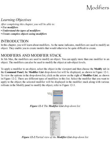
ModifiersLearning ObjectivesAfter completing this chapter, you will be able to: Use modifiers Understand the types of modifiers Create complex objects using modifiersINTRODUCTIONIn this chapter, you will learn about modifiers. As the name indicates, modifiers are used to modify anobject. They enable you to create models that would otherwise be quite difficult to create.MODIFIERS AND MODIFIER STACKIn 3ds Max, the modifiers are used to modify an object. You can apply more than one modifier to anobject. The modifiers can also be used to modify the object at sub-object levels.To apply a modifier to an object, select the object in the viewport and then choose the Modify tab inthe Command Panel; the Modifier List drop-down list will be displayed, as shown in Figure 12-1.To view the options in the drop-down list, click on the arrow on the right of Modifier List, as shownin Figure 12-2. There are different types of modifiers in this list. Select the modifier that you want toapply to the object; the selected modifier will be displayed in the modifier stack along with variousrollouts in the Modify panel to modify the object, refer to Figure 12-3.Figure 12-1 The Modifier List drop-down listFigure 12-2 Partial view of the Modifier List drop-down list
NoteThe modifiers are displayed in the Modifier List drop-down list based on the selection of theobject in the viewport.In the modifier stack, there is a bulb-like button, refer to Figure 12-3. It is used to show or hide theeffects of the modifier in the viewport. By default, this button is active. Click on this button to make itinactive; the button will become dark and the effect of the modifier will not be displayed in theviewport. The buttons at the bottom of the modifier stack are used to manage the modifier stack.These buttons are discussed next.Figure 12-3 The modifier stackThe Pin Stack button is used to lock the modifier stack for the selected object in the viewport. Ifyou choose the Pin Stack button for the selected object in the viewport, and then select another objectin the viewport, the Modify tab will display the modifier stack and the rollouts for the pinned objectonly.The Show end result on/off toggle button is used to toggle the effect of all the modifiers in themodifier stack on the selected object in the viewport. If this button is deactivated, then the selectedobject in the viewport will display only the effect of the selected modifier in the modifier stack.The Make unique button is used to convert an instanced object into a unique copy. On making theinstanced objects unique, they become independent and you can modify them independently withoutaffecting the other objects in the viewport. By default, this button is inactive. When you create theinstance of an object, this button will be activated. Select the instanced object in the viewport andchoose the Make unique button in the modifier stack to make it unique.The Remove modifier from the stack button is used to remove the selected modifier from themodifier stack.The Configure Modifier Sets button is used to control the display of the modifiers in the modifierstack.
Note1. If you change the order of the modifiers applied to an object in the modifier stack, the objectwill display different effects.2. The object should have more number of segments to get the best effect of the applied modifier.In the modifier stack, move the cursor over the modifier and right-click on it; a shortcut menu will bedisplayed, as shown in Figure 12-4. You can rename, delete, cut, copy, or paste the selected modifiersby choosing the corresponding option from the shortcut menu displayed. Choose the Collapse Alloption from the menu to collapse the entire stack; the Warning: Collapse All message box will bedisplayed. Choose the Yes button; all the parameters and modifiers will be replaced by Editable Polyin the modifier stack. Choose the Collapse To option from the shortcut menu to collapse the selectedmodifier along with the modifiers and objects below it.TYPES OF MODIFIERSThere are three categories of modifiers in the Modifier List drop-down list: Selection Modifiers,WORLD-SPACE MODIFIERS, and OBJECT-SPACE MODIFIERS. The Bend and Tapermodifiers from the OBJECT-SPACE MODIFIERS category have already been discussed in Chapter3. The most commonly used modifiers in these three categories are discussed next.Mesh Select ModifierThe Mesh Select modifier is used to access the sub-object levels without converting the object intoeditable mesh. To work with this modifier, select the object in the viewport and choose the Modifytab in the Command Panel. In the modifier stack, click on the arrow on the right side of the ModifierList drop-down list and select the Mesh Select modifier from the Selection Modifiers category.Alternatively, choose Modifiers Selection Modifiers Mesh Select from the menu bar; the MeshSelect modifier will be displayed in the modifier stack with various rollouts in the Modify panel,refer to Figure 12-5. Click on the plus sign ( ) on the left of the Mesh Select modifier in the modifierstack; the sub-object levels will be displayed. Now, select any of the sub-object levels and thenselect the corresponding sub-objects of the object in the viewport. Next, apply another modifier; itwill affect only the selected sub-objects in the viewport. The most commonly used rollout isdiscussed next.Mesh Select Parameters RolloutIn the Mesh Select Parameters rollout, there are five buttons Vertex, Edge, Face, Polygon, andElement. These buttons are used to select the sub-objects of the object and are same as described inChapter 8. Choose any button to activate the sub-object and is same as selecting the sub-object levelin the modifier stack. When you choose any of the buttons, the transform tools such as Select andRotate, Select and Move, and so on will be disabled in the Main Toolbar.
Figure 12-4 The shortcut menu displayed on right-clicking on the modifier in the modifier stackFigure 12-5 Partial view of the rollouts displayed on selecting the Mesh Select modifierThe options in the Get from Other Levels area are used to apply the selection of the sub-objectsfrom one sub-object level to another. The Get Vertex Selection button is available for the Face,Edge, Polygon, and Element sub-object levels. Choose this button to select the faces of the objectbased on the last selection of the vertices. The Get Face Selection button is available only for theVertex and Edge sub-object levels. Choose this button to select the vertices of the object based onthe last selection of the faces, polygons, and elements. The Get Edge Selection button is availablefor the Vertex, Face, Polygon, and Element sub-object levels. Choose this button to select the facesbased on the last selection of the edges.Displace ModifierThe Displace modifier is used to deform the shape of an object. You can distort the object either byusing the gizmo of the modifier or by using the bitmap image. To apply the Displace modifier, selectthe object in the viewport and choose the Modify tab in the Command Panel. Now, click on theModifier List drop-down list and select the Displace modifier from the OBJECT-SPACEMODIFIERS category. Alternatively, choose Modifiers Parametric Deformers Displace fromthe menu bar; the Displace modifier will be displayed in the modifier stack and the Parametersrollout will be displayed in the Modify panel. You need to use the options in this rollout to distort thesurface of the object. These options are discussed next.Parameters Rollout
The most commonly used areas in this rollout are discussed next.Displacement AreaThe options in this area are used to specify the amount ofFigure 12-6 The Displacement area in the Parameters rolloutdisplacement of an object from the position of its gizmo, refer to Figure 12-6. By default, the valuein the Strength and Decay spinners is 0 which indicates that there will be no displacement. Set thevalue more than 0 in the Strength spinner to displace the object away from the gizmo. Set the valueless than 0 in the Strength spinner to displace the object toward the gizmo. Set the value in theDecay spinner to decrease the strength of the displacement based on the distance of the object fromthe gizmo.Image AreaThe options in this area are used to choose a bitmap or map as the source for the displacement. Thebutton labeled as None at the top of the Bitmap group is used to assign a bitmap image to the objectfor displacement. To do so, create a plane with heavy segments and then apply the Displacemodifier. Next, choose the None button from the Bitmap group; the Select Displacement Imagedialog box will be displayed. Select the image of your choice and choose the Open button; thename of the image will be displayed on the button. Next, set the values in the Strength and Decayspinners in the Displacement area to view the displacement, refer to Figures 12-7 and 12-8.Choose the Remove Bitmap button to remove the assigned bitmap image.Figure 12-7 The plane after using the bitmap image in the Displace modifierFigure 12-8 The bitmap image that has been used for displacement in Figure 12-7The button, labeled as None at the top of the Map group, is used to assign a map to the object fordisplacement. To do so, choose the button; the Material/Map Browser dialog box will bedisplayed. Select the map of your choice from the Maps Standard rollout and choose the OK
button; the name of the map will be displayed on the button. Next, set the values in the Strength andDecay spinners in the Displacement area to view the displacement, refer to Figures 12-9 and 1210. Choose the Remove Map button to remove the assigned map. Set the value in the Blur spinnerto soften the edges of the map or bitmap.Figure 12-9 The plane after using the map image in the Displace modifierFigure 12-10 The map image that has been used for displacement in Figure 12-9NoteYou can apply the map and bitmap images simultaneously.Set the parameters in the Map, Channel, and Alignment areas to define the placement or alignment ofthe map on the object.Extrude ModifierThe Extrude modifier is used to convert a 2D spline into a 3D object.Figure 12-11 The Parameters rolloutIt provides thickness and depth to a spline. To apply the Extrude modifier, select the spline in theviewport and choose the Modify tab in the Command Panel. Now, select the Extrude modifier fromthe OBJECT-SPACE MODIFIERS category in the Modifier List drop-down list. Alternatively,choose Modifiers Mesh Editing Extrude from the menu bar; the modifier will be displayed inthe modifier stack and the Parameters rollout will be displayed below the modifier stack in theModify panel, as shown in Figure 12-11. Next, you need to use the options in the Parameters rolloutto view the effects of the Extrude modifier. These options are discussed next.
Parameters RolloutThe Amount spinner in this rollout is used to specify the amount of extrusion of the spline, refer toFigures 12-12 and 12-13. Set the value in the Segments spinner to specify the number of segments inthe extruded object. The areas in this rollout are discussed next.Figure 12-12 The text spline before applying the Extrude modifierFigure 12-13 The text spline after applying the Extrude modifierCapping AreaBy default, the Cap Start and Cap End check boxes are selected in the Capping area. They areused to place a plane surface at the start and end of the extruded object. Clear the Cap Start checkbox to remove the surface at the start of the extruded object. Similarly, clear the Cap End checkbox to remove the surface at the end of the extruded object.Output AreaThe options in this area are used to specify the type of the object to be created by the Extrudemodifier. By default, the Mesh radio button is selected that produces a mesh object. Select thePatch or the NURBS radio button to produce the patch or the nurbs object.Melt ModifierThe Melt modifier is used to apply a realistic melting effect to all typesFigure 12-14 The Parameters rolloutof objects. To apply the Melt modifier, select the editable object in the viewport and choose the
Modify tab in the Command Panel. Now, select the Melt modifier from the OBJECT-SPACEMODIFIERS category in the Modifier List drop-down list. Alternatively, choose Modifiers Animation Melt from the menu bar; the modifier will be displayed in the modifier stack and theParameters rollout will be displayed below the modifier stack in the Modify panel, as shown inFigure 12-14. You can use the options in the Parameters rollout to view the effects of the Meltmodifier. These options are discussed next.Parameters RolloutSet the value in the Amount spinner of the Melt area to specify the amount of melting of the editablepoly, refer to Figure 12-15 and 12-16. Set the value in the % of Melt spinner in the Spread area tospecify the percentage of melting.Figure 12-15 The object beforeapplying the Melt modifierFigure 12-16 The object after applying the Melt modifierSolidity AreaThis area is used to define the relative height of the center of the melted object. This area has fiveradio buttons: Ice, Glass, Jelly, Plastic and Custom. These radio buttons determine the relativeheight of the center of ice, glass, jelly, and plastic. Select the Custom radio button to define thecustom solidity of the object and its melting process that varies between 0.2 to 30.0.Axis to Melt AreaThis area is used to define the axis on which the object will melt. By default, the melting axis is setto Z. You can change it to X and Y, as required.Flip Axis Radio ButtonThe Flip Axis radio button is used to reverse the direction of the selected axis of melting whichnormally occurs from the positive direction to the negative direction.ProOptimizer ModifierThis modifier is used to reduce the number of vertices in an object while preserving the object’sappearance. It helps in reducing a scene’s memory requirements, simplifies the modeling, andimproves the speed of viewport display and render. To apply the ProOptimizer modifier, select the
editable poly object in the viewport and choose the Modify tab in the Command Panel. Now, selectthe ProOptimizer modifier from the OBJECT-SPACE MODIFIERS category in the Modifier Listdrop-down list. Alternatively, choose Modifiers Mesh Editing ProOptimizer from the menu bar;the modifier will be displayed in the modifier stack and the Optimization Level rollout will bedisplayed below the modifier stack in the Modify Panel, as shown in Figure 12-17. Next, you need touse the options in the Optimization Level rollout to view the effects of the ProOptimizer modifier.This rollout is discussed next.Figure 12-17 The Optimization Level rolloutOpitimization Level RolloutThe Calculate button in the Optimization Level rollout is used to calculate the total number ofvertices and faces. Set the value in the Vertex % spinner of the Optimization Level area to specifythe percentage of the vertices that should be reduced, refer to Figures 12-18 and 12-19.Figure 12-18 The object before applying the ProOptimizer modifierFigure 12-19 The object after applying the ProOptimizer modifierSet the value in the Vertex Count spinner of the Optimization Level rollout to specify the amount ofvertices in the object. The Status window in this rollout is used to display the status of theProOptimizer modifier. Before the Calculate button is chosen, the Status window will display thetext, Modifier Ready. However, after choosing the Calculate button, it will display the statistics thatdescribes the before and after effects on the vertex and face count of an object.Face Extrude ModifierThis modifier is used to extrude the selected faces along their normals. A normal is an invisible linecoming straight out of a face in a particular direction. To apply the Face Extrude modifier, firstconvert the object into editable poly object. Next, select the Face sub-object level and then select thefaces of the object in the viewport. Now, select the Face Extrude modifier from the OBJECTSPACE MODIFIERS category in the Modifier List drop-down list.
Alternatively, choose Modifiers Mesh Editing Face Extrude from the menu bar; the FaceExtrude modifier will be displayed in the modifier stack and also the Parameters rollout will bedisplayed below the modifier stack in the Modify Panel, as shown in Figure 12-20. Now, you need touse the options in the Parameters rollout to view the effect of the Face Extrude modifier on theselected faces, refer to Figure 12-20. These options are discussed next.Figure 12-20 The Parameters rolloutParameters RolloutThe Amount spinner of the Parameters area in this rollout is used to specify the amount of extrusionof the selected faces, refer to Figures 12-21 and 12-22. Set the value in the Scale spinner to specifythe percentage of the original face size used for the extruded face.Figure 12-21 The faces selected to be extruded in a sphereFigure 12-22 The selected faces extrudedLattice ModifierThe Lattice modifier is used to convert the segments or edges of an object or shape into wireframesor cylindrical struts. To apply the Lattice modifier, select the object or shape in the viewport andchoose the Modify tab in the Command Panel. Now, select the Lattice modifier from the OBJECTSPACE MODIFIERS category in the Modifier List drop-down list. Alternatively, choose Modifiers Parametric Deformers Lattice from the menu bar; the modifier will be displayed in themodifier stack and its effect will be displayed on the object, as shown in Figure 12-23. TheParameters rollout will also be displayed below the modifier stack, as shown in Figure 12-24. Now,you need to use the options in the Parameters rollout to modify the effects of the Lattice modifier.These options are discussed next.
Figure 12-23 The sphere after applying the Lattice modifierFigure 12-24 Partial view of the Parameters rolloutParameters RolloutThe options in this rollout are used to specify whether the wireframes will be displayed on the joints,struts, or both of them. The areas in this rollout are discussed next.Geometry AreaIn this area, the Apply to Entire Object check box is selected by default. As a result, wireframe isapplied to all the segments or edges of the object. If you clear this check box, then the wireframeswill be applied only to the selected segments or edges of the object.By default, the Both radio button is selected to apply the wireframes both on the struts and joints,refer to Figure 12-24. Select the Joints Only from Vertices radio button to display the wireframesonly on the joints generated from the vertices of the object, as shown in Figure 12-25. Select theStruts Only from Edges radio button to display the wireframes only on the struts generated fromthe edges of the object, as shown in Figure 12-26.Figure 12-25 The sphere after selecting the Joints Only from Vertices radio buttonFigure 12-26 The sphere after selecting the Struts Only from Edges radio buttonStruts AreaThe options in this area are activated only if the Struts Only from Edges or Both radio button isselected in the Geometry area. Set the value in the Radius spinner to define the radius of the struts.Set the value in the Segments spinner to specify the number of segments along the struts. Set the
value in the Sides spinner to specify the number of sides around the circumference of the struts. Setthe value in the Material ID spinner to specify the material id for the struts to apply the material.Joints AreaThe options in this area are activated only if the Joints Only from Vertices or Both radio button isselected in the Geometry area. There are three radio buttons in the Geodesic Base Type groupthat specify the type of polyhedron to be used for the joints. By default, the Octa radio button isselected and is used to create the octahedron joints. Select the Tetra or the Icosa radio button tocreate the tetrahedron or icosahedron joints, respectively. The other options are the same asdiscussed in the Struts area.Material ModifierThe Material modifier is used to assign material ID to an object or sub-objects. The material ID ofan object is the value given to specify the sub-material that is applied to it from the Multi/SubObject material. You can apply different materials to the selected sub-objects by assigning differentmaterial IDs to them. To do so, create an object in the Top viewport. Choose the Material Editor toolfrom the Main Toolbar and apply the Multi/Sub-Object material to the object, as described earlierin Chapter 7; the Multi/Sub-Object Basic Parameters rollout will be displayed in the MaterialEditor dialog box, as shown in Figure 12-27. In this rollout, assign two different colors to the firsttwo sub-materials using the color swatches on the right side. By default, the first two sub-materialshave the material IDs, 1 and 2. Now, assign the Multi/Sub-Object material to the object in theviewport. Next, make sure that the object is selected and apply the Mesh Select modifier to it. Selectthe Polygon sub-object level and select the polygons of the object in the viewport. Now, make surethat the Polygon sub-object level is active and select the Material modifier from the OBJECTSPACE MODIFIERS category in the Modifier List drop-down list. You can also choose Modifiers Surface Material from the menu bar; the Material modifier will be displayed in the modifierstack and the Parameters rollout will be displayed. Now, in the Material ID spinner of theParameters rollout, set the value 1; the selected polygons will display the color that you haveassigned to the sub-material with the material ID 1. Select another set of polygons and set the value 2in the Material ID spinner; the selected polygons will display the color that you have assigned to thesub-material with the material ID 2.The options in the Parameters rollout are discussed next.Parameters RolloutThe Material ID spinner in this rollout is used to change the material ID of the selected sub-object inthe viewport. Set the value in the Material ID spinner that you have assigned in the Multi/SubObject Basic Parameters rollout; the selected sub-objects will display the color of the samematerial ID. For example, if you have assigned yellow color to the material ID 1 and red color to thematerial ID 2 in the Multi/Sub-Object Basic Parameters then on entering the value 1 in theMaterial ID spinner, the selected sub-objects will appear yellow. If you enter the value 2 in theMaterial ID spinner, the selected sub-objects will appear red, refer to Figure 12-28.
Figure 12-27 Partial view of the Multi/Sub-Object Basic Parameters rollout inthe Material Editor dialog boxFigure 12-28 The object displayed in two different colors after applying the Material modifierNoise ModifierThe Noise modifier is used to generate disturbances on the surface of an objectto create irregular surfaces. It can also be used to animate the water or wavy surfaces.Figure 12-29 The Parameters rolloutTo apply the Noise modifier, select the object in the viewport and choose the Modify tab in theCommand Panel. Now, select the Noise modifier from the OBJECT-SPACE MODIFIERS categoryin the Modifier List drop-down list. You can also choose Modifiers Parametric Deformers Noise from the menu bar; the Noise modifier will be displayed in the modifier stack and theParameters rollout will also be displayed in the Modify panel. Next, you need to use the options inthe Parameters rollout, refer to Figure 12-29, to apply the effects of the Noise modifier on theselected object. These options are discussed next.Parameters RolloutThe options in this rollout are used to generate noise effects in an object, as shown in Figure 12-30.The areas in this rollout are discussed next.
Noise AreaThe options in this area are used to define the appearance of the surface of the object on applyingthe Noise modifier. Set the value in the Seed spinner to specify the starting point for generating thenoise randomly in the object. Set the value in the Scale spinner to specify the size of noise effects.By default, the value in the Scale spinner is 100. A higher value in this spinner produces smoothernoise effects and a lower value produces scraggy noise effects. By default, the Fractal check box iscleared. Select the Fractal check box to produce the fractal-based noise effects, refer to Figure 1231. When you select the Fractal check box, the Roughness and Iterations spinners get activatedthat are used to set the fractal effects in the noise. Set the lower value in the Roughness spinner toproduce smooth fractal effects in noise. Set the higher value in the Roughness spinner to producerough fractal effects in noise. The value in the Roughness spinner varies from 0 to 1.0. Set thevalue in the Iterations spinner to apply the fractal effects multiple times. By default, the value inthe Iterations spinner is 1.0. It varies from 1.0 to 10.0.Figure 12-30 The plane with the Noise modifier appliedFigure 12-31 The plane with the Fractal checkbox selectedNote1. The number of segments in an object should be more to generate a better effect of the Noisemodifier.2. You can also create the terrain objects using this modifier.Strength AreaThe options in this area are used to specify the strength of the noise effects. By default, the value inthe X, Y, and Z spinners is 0 that produces no noise effects in the object. Set the value in thesespinners to generate the strength of the noise effects.Animation AreaThe options in this area are used to animate the noise effects of the object. To view the animationeffects, you need to select the Animate Noise check box. Set the value in the Frequency spinner tospecify the speed of the animation of noise waves. The lower value produces a slow animation andthe higher value produces a fast animation. Set the value in the Phase spinner to set the start pointand the end point of the wave animation along with the frames in the time slider.
Twist ModifierThe Twist modifier is used to produce the swirling effect on an object. To apply the Twist modifier,select an object in the viewport. Select the Twist modifier from the OBJECT-SPACE MODIFIERScategory in the Modifier List drop-down list. Alternatively, choose the Modifiers ParametricDeformers Twist from the menuFigure 12-32 The Parameters rolloutbar; the Twist modifier will be displayed in the modifier stack and the Parameters rollout will alsobe displayed in the Modify panel. Next, you need to use the options in the Parameters rollout, referto Figure 12-32, to apply the effects of the Twist modifier to the object. The Parameters rollout isdiscussed next.Parameters RolloutThis rollout is used to set the parameters to generate the swirling effects on an object, as shown inFigure 12-33. The areas in this rollout are discussed next.Twist AreaSet the value in the Angle spinner to specify the amount of twist in degrees along the selected axisin the Twist Axis area. Set the value in the Bias spinner to shift the twist at one of the ends of theobject. By default, the value in this spinner is 0, which specifies that the twist is uniform along thelength of the object. It varies from 100 to -100.Twist Axis AreaBy default, the Z radio button is selected. As a result, the object will twist along the Z-axis. Selectthe X or the Y radio button to twist the object along the X-axis or the Y-axis, respectively.Limits AreaThe options in this area are used to define the portion of an object to which the twist effects will beapplied, refer to Figure 12-34. Select the Limit Effect check box to apply the limits to the twisteffects of the object. Set the value in the Upper Limit spinner to specify the upper limit for thetwist effect. Set the value in the Lower Limit spinner to specify the lower limit for the twist effect.
Figure 12-33 The Twist modifier applied to the pyramid objectFigure 12-34 The Twist modifier applied to a portion of the pyramid object using the options inthe Limits areaLathe ModifierThe Lathe modifier is a shape modifier that is used to create a 3D object by rotating a shape about anaxis. The direction of the axis of revolution depends on the pivot point of the shape. To apply theLathe modifier on an object, create a shape with the spline in the Front viewport and choose theModify tab in the Command Panel. Now, select the Lathe modifier from the OBJECT-SPACEMODIFIERS category in the Modifier List drop-down list. Alternatively, choose Modifiers Patch/Spline Editing Lathe from the menu bar; the 2D shape will be converted into a 3D object,as shown in Figures 12-35 and 12-36. And, the modifier will be displayed in the modifier stack. TheParameters rollout will also be displayed below the modifier stack, refer to Figure 12-37. Thisrollout is discussed next.Figure 12-35 The Line splinecreated to apply the Lathe modifierFigure 12-36 The Line spline after applying the Lathe modifier
Figure 12-37 Partial view of the Parameters rolloutParameters RolloutSet the value in the Degrees spinner to specify the amount of rotation of the object in degrees aroundthe axis specified in the Direction area. The Weld Core check box is used to weld the vertices whichare on the axis of revolution. The Flip Normals check box is used to flip the normals of the lathedobject. Set the value in the Segments spinner to specify the desired number of segments around theaxis of revolution. The areas in this rollout are discussed next.Capping AreaThe options in this area are the same as described in the Extrude modifier.Direction AreaChoose the X, Y, or Z button to specify the axis around which the objects will rotate while applyingthe Lathe modifier.Align AreaChoose the Min, Center, or Max button to align the spline with the axis of revolution.MeshSmooth ModifierThe MeshSmooth modifier is used to produce smoothness in 3D mesh objects. To apply theMeshSmooth modifier, select an object in the viewport. Select the MeshSmooth modifier from theOBJECT-SPACE MODIFI
In 3ds Max, the modifiers are used to modify an object. You can apply more than one modifier to an object. The modifiers can also be used to modify the object at sub-object levels. To apply a modifier to an object, select the object in the viewport and then choose the Modify tab in